WiFi Modules for Long-Range & Anti-Interference Industrial Use: Technical Deep Dive for Engineers and System Integrators
This article is written for industrial wireless engineers and system integrators evaluating WiFi modules for deployment in factories, oil and gas facilities, mining operations, and other heavy industrial environments. We cover the RF parameters that govern long-range transmission, the interference sources unique to industrial settings, the anti-interference technologies available at the module level, and practical deployment considerations. The focus throughout is on engineering fundamentals and spec-level decision criteria, not vendor comparisons.
Industrial WiFi modules engineered for long-range transmission and interference rejection operate on a fundamentally different level than consumer-grade hardware — in RF architecture, link budgeting, and electromagnetic resilience. This article breaks down the core technical specs you need to know: transmit power ratings from +18 dBm to +30 dBm, receive sensitivity down to −98 dBm (2.4 GHz) and −95 dBm (5 GHz), line-of-sight transmission beyond 600 m on 2.4 GHz and 400 m on 5 GHz, concrete wall attenuation of 10–15 dB per layer, and industrial EMC immunity per IEC 61000-6-2 (Level 3/4). We cover wireless link budget fundamentals, common industrial interference sources, anti-interference mechanisms including dynamic frequency selection and MU-MIMO, wall penetration loss characterization, real-world deployment scenarios across factory complexes, oil pipeline corridors, and mining sites — plus expert selection criteria and best practices for industrial wireless engineers.
Industrial WiFi Module Basics for Long-Range & Anti-Interference
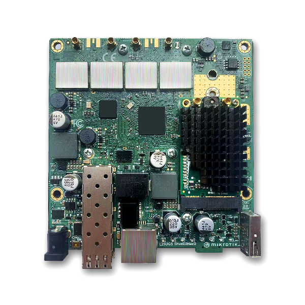
Industrial WiFi modules are purpose-built radio subsystems designed to operate in environments where standard commercial WiFi gear cannot deliver reliable connectivity. Unlike the access points and routers used in office or home setups, industrial WiFi modules prioritize link reliability over raw throughput, spectral resilience over convenience, and extended physical range over device density. These modules are typically embedded into programmable logic controllers (PLCs), remote terminal units (RTUs), industrial gateways, and field-deployed sensor arrays.
At the core of an industrial long-range WiFi module, you will find a high-linearity power amplifier (PA), a low-noise amplifier (LNA) with a noise figure typically below 1.5 dB, a front-end module (FEM) with integrated filtering, and often a temperature-compensated crystal oscillator (TCXO) to maintain frequency stability across the −40 °C to +85 °C industrial temperature range. Many modules also incorporate digital pre-distortion (DPD) and adaptive gain control to keep EVM (Error Vector Magnitude) within specification at maximum transmit power.
Interference rejection is built into both the PHY and MAC layers. Industrial modules implement coexistence mechanisms that go beyond standard EDCA (Enhanced Distributed Channel Access). You get PTA (Packet Traffic Arbitration) for co-located radios, dynamic channel selection based on real-time CCA (Clear Channel Assessment), and configurable output power back-off schemes to minimize adjacent-channel interference in dense deployments.
Industrial vs Consumer WiFi Modules: Long-Range & Anti-Interference Gap
The gap between industrial-grade and consumer-grade WiFi modules is rooted in differences in component selection, engineering margin, and design priorities. Here is a direct technical comparison across the parameters that matter most for long-range and interference-heavy environments.
| Parameter | Industrial WiFi Module | Consumer WiFi Module |
|---|---|---|
| Transmit Power (2.4 GHz) | +18 to +30 dBm (with FEM) | +14 to +18 dBm (typical) |
| Receive Sensitivity (HT20 MCS7) | −73 to −75 dBm (2.4 GHz) | −68 to −70 dBm (2.4 GHz) |
| Operating Temperature Range | −40 °C to +85 °C | 0 °C to +40 °C |
| ESD Immunity (IEC 61000-4-2) | ±8 kV contact / ±15 kV air | ±2 kV contact / ±4 kV air |
| Conducted RF Immunity (IEC 61000-4-6) | 10 Vrms, 150 kHz – 80 MHz | 3 Vrms or none |
| Surge Immunity (IEC 61000-4-5) | ±2 kV line-to-line / ±4 kV line-to-earth | ±0.5 kV or none |
| Link Budget (typical) | 110–120 dB | 85–95 dB |
| LNA Noise Figure | < 1.5 dB | 2.5–4 dB |
| PA Efficiency | > 30% at P1dB | 15–22% at P1dB |
| Frequency Stability (TCXO) | ±2 ppm or better | ±10 to ±25 ppm |
| Channel Coexistence | PTA, DCS, DFS | Basic EDCA only |
Industrial modules also include hardware-level filtering — SAW (Surface Acoustic Wave) band-pass filters and BAW (Bulk Acoustic Wave) filters at the RF front end — that consumer modules typically omit to reduce BOM cost. These filters deliver 20–40 dB of out-of-band rejection, which is critical when the module is operating near Variable Frequency Drives (VFDs), welding equipment, or high-power switching power supplies that generate broadband noise across the 2.4 GHz and 5 GHz bands.
Key RF Parameters for Industrial Long-Range WiFi Transmission
Long-range WiFi in industrial environments depends on five interrelated RF parameters. Understanding how these parameters interact is necessary to select the right module for a given deployment.
3.1 Transmit Power (Tx Power)
Industrial WiFi modules typically deliver transmit power from +18 dBm to +30 dBm, depending on the standard, band, and regional regulatory limits (FCC Part 15.247, ETSI EN 300 328). High-end industrial modules based on chipsets such as the Qualcomm IPQ8074 deliver up to +20 dBm per chain in 802.11ax mode, while modules using high-power FEMs like the Skyworks SKY85716-11 (with a P1dB of approximately +30 dBm) can reach +28 to +30 dBm at the module output on 2.4 GHz under FCC Part 15.247 point-to-point rules. Note that ETSI EN 300 328 (EU) restricts 2.4 GHz EIRP to +20 dBm for non-adaptive systems, significantly lower than FCC’s +36 dBm EIRP limit — system integrators for EU deployments must factor this into their link budget calculations. Cranking up the power must be balanced against linearity: operating too close to P1dB degrades EVM, increases spectral regrowth, and risks violating emission masks.
3.2 Receive Sensitivity (Rx Sensitivity)
Receive sensitivity indicates the weakest signal a module can still demodulate reliably. Industrial modules with quality LNAs achieve sensitivity figures of −98 dBm for 802.11b 1 Mbps, −91 dBm for HT20 MCS0, and −73 to −75 dBm for HT20 MCS7 at 2.4 GHz. On 5 GHz, typical figures are −95 dBm (VHT20 MCS0) and −63 dBm (VHT80 MCS9). Every 3 dB improvement in sensitivity roughly doubles the usable range in noise-limited environments.
3.3 Antenna Gain & Diversity
Industrial long-range links almost always use directional or sector antennas with gain from 8 dBi to 24 dBi. The Friis transmission equation governs how antenna gain translates to range. For an industrial module pushing +23 dBm through an 18 dBi dish antenna, the effective isotropic radiated power (EIRP) reaches +41 dBm, pushing line-of-sight range out to several kilometers. Maximum Ratio Combining (MRC) in 2×2 MIMO configurations adds 3–5 dB of diversity gain in multipath-rich industrial environments.
3.4 Modulation and Coding Scheme (MCS) Adaptation
Industrial long-range modules use robust MCS fallback algorithms. When the link budget is tight, the module automatically drops from 256-QAM (MCS7/8) down to QPSK (MCS1) or even BPSK (MCS0), trading throughput for range. For critical control applications, engineers often lock the MCS to a lower index (e.g., MCS1 or MCS2) to maintain a 6–10 dB link margin above the sensitivity threshold, keeping retry rates under 5%.
3.5 Error Vector Magnitude (EVM)
EVM measures modulation quality. Industrial modules need to maintain EVM better than −28 dB for 64-QAM and −32 dB for 256-QAM at their rated transmit power. Poor EVM from PA nonlinearity or phase noise increases packet error rate (PER), which affects long-range links especially hard since retransmission overhead reduces effective throughput.
Wireless Link Budget & Distance Attenuation Principle
The wireless link budget is the most important calculation for determining whether a given industrial WiFi module can close a long-range link. It is an accounting exercise — summing all the gains and subtracting all the losses in the transmission path.
Received Power (dBm) = Tx Power (dBm) + Tx Antenna Gain (dBi) − Tx Cable Loss (dB) − Path Loss (dB) + Rx Antenna Gain (dBi) − Rx Cable Loss (dB)
Rule of Thumb: A link budget of 110–115 dB typically supports 400–800 m on 2.4 GHz line-of-sight. Every 6 dB of additional budget doubles the distance in free space.
Path Loss in Industrial Environments
Free-space path loss (FSPL) is calculated as:
FSPL (dB) = 32.45 + 20 × log₁₀(f[MHz]) + 20 × log₁₀(d[km])
At 2.4 GHz over 500 m, FSPL is approximately 94 dB. At 5.8 GHz over the same distance, it is approximately 102 dB — about 6 dB higher due to the frequency term in the equation. In real industrial environments, an additional 5–15 dB must be added for reflection, diffraction, absorption, and multipath fading.
For outdoor industrial links — such as between a control room and a remote oil well pump station — the link budget must also account for foliage loss (2–5 dB per 10 m of dense vegetation), Fresnel zone obstruction (which becomes critical beyond 500 m), and atmospheric absorption (negligible below 10 GHz but measurable in high humidity).
Always maintain at least 10 dB of link margin above the receiver’s sensitivity threshold to ensure reliability through rain fade, thermal drift, and interference. If the Rx sensitivity is −90 dBm at the chosen MCS, the predicted received power should be −80 dBm or better under worst-case conditions.
| Distance (LOS) | 2.4 GHz FSPL | 5 GHz FSPL | Link Budget Required |
|---|---|---|---|
| 100 m | 80 dB | 88 dB | 90–100 dB |
| 300 m | 89 dB | 97 dB | 100–110 dB |
| 600 m | 96 dB | 104 dB | 110–120 dB |
| 1 km | 100 dB | 108 dB | 115–125 dB |
| 3 km | 110 dB | 118 dB | 125–135 dB |
Industrial Interference Sources & Impact on WiFi Performance
Industrial environments generate electromagnetic interference (EMI) at levels far beyond what is seen in residential or office settings. Identifying each interference type is the first step in designing a robust wireless link.
5.1 Variable Frequency Drives (VFDs) and Motor Controllers
VFDs generate broadband conducted and radiated emissions from 30 kHz to 30 MHz, with harmonics that extend into the 2.4 GHz ISM band. PWM switching at 2–16 kHz creates harmonics that couple into unshielded cables and radiate from motor leads. Typical field measurements indicate that a 75 kW VFD located 3 m away can produce electric field strengths of 10–20 V/m across the 2.4 GHz band, which can push a WiFi receiver’s noise floor up by 8–12 dB.
5.2 High-Voltage Switching Gear and Arc Welding
Contactors, circuit breakers, and arc welders generate impulsive noise with burst durations of 1–100 μs and amplitudes that can saturate standard AGC circuits. Packet corruption can persist beyond the impulse duration because AGC recovery time extends the window of vulnerability. Modules without fast AGC (recovery under 5 μs) can experience PER spikes above 30% during welding operations.
5.3 Co-located Wireless Systems
Industrial facilities increasingly deploy multiple wireless technologies in close quarters: WiFi (2.4/5 GHz), Zigbee (2.4 GHz), Bluetooth (2.4 GHz), LoRa (Sub-1 GHz), 4G/5G cellular, and proprietary ISM-band links. The cumulative interference can raise the ambient noise floor from −100 dBm (typical quiet industrial) to −85 dBm or higher, reducing the WiFi receiver’s usable dynamic range by 15 dB or more.
5.4 Building Infrastructure Obstructions
Reinforced concrete with steel rebar, corrugated metal roofing, metal cable trays, and piping all create reflective surfaces that cause deep frequency-selective fading. In a typical factory building, the channel’s coherence bandwidth can drop below 5 MHz, meaning a standard 20 MHz WiFi channel will encounter multiple nulls across its passband.
Core Anti-Interference Technologies of Industrial WiFi Modules
Industrial WiFi modules address interference at multiple levels — component, PHY, MAC, and network.
6.1 Dynamic Frequency Selection (DFS) and Adaptive Channel Selection
DFS enables modules to operate on 5 GHz channels that are also used by radar systems, with the requirement (per FCC and ETSI regulations) that the module vacate the channel within 10 seconds of detecting radar. In practice, industrial modules use DFS to access additional channels beyond the four non-DFS 5 GHz channels, which helps distribute co-channel interference in dense deployments. Adaptive channel selection goes further: the module continuously monitors CCA measurements across all available channels and shifts to a less congested channel when the noise floor on the current channel rises above a programmable threshold (typically −85 dBm to −75 dBm). Engineers should note that DFS channel changes can disrupt active links for several seconds, so link-layer retry mechanisms and session persistence must be designed accordingly.
6.2 Hardware-Level Filtering: SAW and BAW Filters
SAW (Surface Acoustic Wave) and BAW (Bulk Acoustic Wave) filters at the RF front end provide 25–40 dB of out-of-band rejection. These filters attenuate interference from adjacent frequency bands — for example, a 2.4 GHz SAW filter can reject a 5 GHz Wi-Fi signal or a 2.5 GHz LTE signal by more than 30 dB. Consumer modules typically rely on PCB-integrated band-pass filtering that offers only 8–12 dB of rejection.
6.3 Fast Automatic Gain Control (AGC)
Fast AGC circuits with attack times under 1 μs and recovery times under 5 μs allow the receiver to handle burst interference from welding, switching gear, and motor startups without losing multiple packets. The AGC adjusts the LNA and mixer gain stages to prevent ADC saturation, then recovers quickly once the interference pulse ends.
6.4 MU-MIMO and OFDMA
Multi-User MIMO (MU-MIMO) in 802.11ac Wave 2 and 802.11ax allows the module to serve multiple clients simultaneously, improving spectral efficiency in dense deployments. OFDMA (Orthogonal Frequency Division Multiple Access) in 802.11ax concentrates power into narrow subchannels (Resource Units as small as 2.03 MHz for a 26-tone RU), which improves SNR by 6–10 dB at low data rates compared to 802.11ac’s full-channel allocation. This translates to more stable links at extended range, especially in interference-heavy environments.
6.5 Programmable CCA Threshold
Industrial modules expose the CCA threshold as a configurable parameter, typically from −82 dBm to −62 dBm. Raising the CCA threshold makes the module less sensitive to distant or weak interference, which can improve throughput in noisy environments at the cost of increased collision probability. Lowering the threshold makes the module more conservative, reducing collisions but potentially causing it to defer transmissions unnecessarily in high-noise environments.
Wall Penetration and 2.4 GHz vs 5 GHz Trade-Off in Industrial Buildings
In multi-building industrial campuses, signal penetration through reinforced concrete walls is often the limiting factor. Understanding the attenuation characteristics of each band is essential for frequency planning.
| Obstruction Type | 2.4 GHz Attenuation | 5 GHz Attenuation |
|---|---|---|
| Drywall (15 cm) | 2–4 dB | 3–6 dB |
| Reinforced Concrete Wall (30 cm) | 12–15 dB | 20–25 dB |
| Metal Fire Door | 10–15 dB | 18–25 dB |
| Wire Glass Window | 5–8 dB | 10–15 dB |
| Concrete Floor (30 cm) | 15–20 dB | 25–35 dB |
Two concrete walls at 2.4 GHz add 24–30 dB of loss, which is manageable for most industrial modules. The same two walls at 5 GHz add 40–50 dB — enough to push the link below the sensitivity threshold for all but the highest-power configurations. For multi-wall industrial environments, 2.4 GHz is typically the practical choice.
Where both bands are available, a dual-band concurrent approach works well: 2.4 GHz for control and telemetry traffic that needs to penetrate multiple walls, and 5 GHz for high-throughput data upload in areas where path loss is manageable and the link can maintain higher MCS indices.
Typical Industrial Scenarios Requiring Long-Range & Anti-Interference
8.1 Factory Complex and Campus-Scale Coverage
In a 500 m × 300 m industrial campus, the control center needs to communicate with PLCs, AGVs, and sensors spread across multiple buildings. Industrial WiFi modules on rooftop masts with 12–18 dBi sector antennas provide campus-wide coverage. Each module must handle interference from overhead cranes, welding stations, and neighboring production lines. Modules with DFS-enabled 5 GHz channels and programmable CCA thresholds (from −82 dBm to −62 dBm) are important for maintaining stable links.
8.2 Oil and Gas Pipeline Monitoring
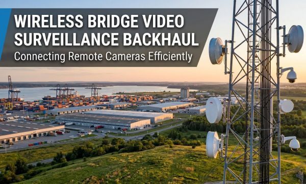
Pipeline right-of-way (ROW) monitoring requires linear WiFi coverage along 10–50 km of pipeline. Modules running 2.4 GHz at +28 dBm transmit power through 18 dBi directional antennas on 15 m towers can achieve 3–5 km per hop. The main interference challenges are cathodic protection rectifiers (which generate pulsing DC magnetic fields) and co-located SCADA radios. Industrial modules with SAW filtering and fast AGC are necessary in this environment.
8.3 Mining Operations (Open-Pit and Underground)
Open-pit mines need communication between the control room, haul trucks, and drill rigs across 2–5 km. 5 GHz is often the better choice here because the open terrain minimizes wall penetration requirements and there is typically less co-channel interference compared to 2.4 GHz. Underground mines present the most challenging environment: tunnels with 100% reinforced concrete, sharp bends, and water ingress push path loss to 120–140 dB at 2.4 GHz over just 300 m. The standard approach is leaky feeder cable systems supplemented with industrial WiFi modules every 100–200 m.
8.4 Remote Oil Well and Water Treatment Sites
At remote well sites, the industrial WiFi module must connect to a base station 1–5 km away over open terrain. Seasonal foliage changes can add 10–20 dB of loss. Modules with adaptive MCS and automatic power control (APC) that compensates for rain and foliage fade by up to 6 dB in real time are important for maintaining uptime above 99.5%.
Selection Criteria for Long-Range Anti-Interference Industrial WiFi Modules
System integrators and industrial wireless engineers should evaluate modules against the following criteria hierarchy:
- Link Budget Requirement: Calculate the required link budget based on distance and obstacle loss. Select a module with at least 10–15 dB margin above that requirement.
- Interference Environment Classification: Define the IEC 61000-6-2 immunity level needed. Heavy industrial (steel mills, foundries, welding) requires Level 4. Light industrial (warehouses, assembly lines) — Level 3 is typically sufficient.
- Temperature and Environmental Rating: Verify the module’s rated temperature range. Extended industrial grade (−40 °C to +85 °C) is mandatory for outdoor and unenclosed deployments.
- FEM and LNA Integration: Look for modules with integrated high-power FEM and low-noise LNA (NF < 1.5 dB). External PA/LNA adds cost and complexity.
- Channel Management Features: Ensure the module supports DFS, adaptive channel selection, and programmable CCA threshold. For extreme interference environments, additional features such as bandwidth-based switching are beneficial.
- MIMO Configuration: 2×2 MIMO is the minimum for diversity gain. 4×4 MIMO provides additional spatial processing gain and is recommended for links over 1 km or in high-multipath factory environments.
- Regulatory Compliance: Confirm FCC (US), CE/ETSI (EU), IC (Canada), and local regulatory compliance. Note that ETSI power limits are significantly lower than FCC limits, which affects achievable range in EU deployments.
Quick Comparison Table: Recommended Industrial WiFi Module Configurations
| Parameter | Light Industrial (Warehouse / Assembly) | Heavy Industrial (Factory / Mining / Oil & Gas) |
|---|---|---|
| Tx Power | +18 to +23 dBm | +23 to +30 dBm |
| Rx Sensitivity | −92 to −95 dBm (2.4 GHz) | −95 to −98 dBm (2.4 GHz) |
| Band Preference | 5 GHz preferred | 2.4 GHz primary / 5 GHz secondary |
| Antenna Type | Omni 5–8 dBi or Panel 10–14 dBi | Directional Panel 14–18 dBi or Dish 18–24 dBi |
| Temperature Range | −20 °C to +55 °C | −40 °C to +85 °C |
| EMC Immunity | IEC 61000-6-2 Level 2 | IEC 61000-6-2 Level 3/4 |
| MIMO Config | 2×2 | 4×4 MU-MIMO |
| LNA NF | < 2.5 dB | < 1.5 dB |
| DFS Channels | Not required | Required |
Deployment Best Practices & Common Layout Mistakes
Deployment quality matters as much as module selection. The best industrial WiFi module will not deliver long-range anti-interference performance if common engineering mistakes are made during installation.
10.1 Antenna Placement and Cable Loss Management
The most frequent mistake is underestimating cable loss at 2.4 GHz, and especially at 5 GHz. A 10 m run of RG58 loses 5–7 dB at 2.4 GHz and 10–14 dB at 5 GHz — enough to eliminate the gain from a high-power FEM. Use LMR-400 or equivalent low-loss cable for runs over 3 m. Keep antenna cable under 1 m for 5 GHz links where possible, or mount the module at the antenna feed point in a weatherproof enclosure.
10.2 Channel Planning and Co-Channel Interference
In dense industrial deployments with multiple access points, poor channel reuse can reduce throughput by 40–60% due to co-channel interference. Use channels 1, 6, and 11 in 2.4 GHz — the only non-overlapping channels. For 5 GHz, use DFS channels to expand the available pool. Maintain a minimum co-channel separation of 3 cell radii (roughly 150–300 m in factory environments) to keep the carrier-to-interference ratio above 19 dB.
10.3 Fresnel Zone Clearance Violation
For outdoor long-range links, at least 60% Fresnel zone clearance is required with no obstructions. The Fresnel zone radius at the midpoint of a 1 km link at 2.4 GHz is approximately 5.6 m. Mount antennas at least 8–10 m above ground to clear the first Fresnel zone. A common mistake is mounting antennas at 3–4 m height for a 500 m+ link, which allows the Fresnel zone to intersect the ground and adds 15–25 dB of unnecessary loss.
10.4 Grounding and Lightning Protection
Outdoor industrial WiFi installations require proper lightning arrestors on the antenna feed line (gas discharge tube type, rated for the operating band), direct grounding of the module enclosure to the facility grounding grid (resistance under 5 Ω), and secondary surge protection on the Ethernet/PoE interface per IEC 61000-4-5 Level 4. Inadequate grounding is the single most common cause of outdoor industrial WiFi deployment failures.
10.5 Thermal Management in Enclosures
Industrial WiFi modules dissipating 5–15 W (4×4 MIMO 802.11ax modules at full transmit power) need active or passive thermal management. In sealed IP67 enclosures with no ventilation, internal temperatures can rise 30–40 °C above ambient — potentially exceeding the module’s rated +85 °C limit on a 50 °C day. Use thermal pads to couple the module to the enclosure wall, or specify a module with an integrated heatsink and forced-air cooling for high-duty-cycle deployments.
10.6 Firmware and Driver Configuration for Stability
Industrial modules often require non-default driver parameters for optimal stability:
- Disable power save modes on client-side modules to prevent latency spikes — set
power_save=offin the driver configuration. - Set beacon interval to 100–200 ms (default 100 ms is fine; intervals above 300 ms cause association instability in noisy environments).
- Configure RTS/CTS threshold to 500–1000 bytes in high-interference environments to reduce hidden-node collisions.
- Disable 40 MHz channel bonding in 2.4 GHz in dense deployments — the adjacent-channel interference penalty typically outweighs the throughput gain.
Conclusion: Core Takeaways for Industrial Wireless Engineers
Selecting and deploying WiFi modules for long-range, interference-heavy industrial use requires a rigorous engineering approach based on link budget calculations, interference source analysis, and module specification verification. Here are the key takeaways:
- Link budget is where you start — no exceptions. Calculate the required link budget before evaluating modules. Industrial modules provide 110–120 dB budgets versus 85–95 dB for consumer parts — that 20–30 dB margin is what makes kilometer-range links feasible.
- Industrial EMC immunity is not optional. Modules in factory, mining, or oil and gas environments must meet IEC 61000-6-2 Level 3 or Level 4. The additional cost of industrial-grade filtering, surge protection, and temperature-rated components is small compared to the cost of a field failure.
- Anti-interference is a layered system, not a single feature. DFS, SAW/BAW filtering, fast AGC, programmable CCA, and MU-MIMO/OFDMA work together. A module with only one of these capabilities is insufficient for heavy industrial environments.
- Antenna selection and deployment matter as much as the module itself. A +30 dBm module with a 2 dBi omnidirectional antenna will be outperformed by a +20 dBm module with an 18 dBi directional antenna at long range.
- Field testing under real interference conditions is mandatory. Lab benchmarks without interference do not predict field performance. Run at least 72 hours of continuous PER and RSSI logging at the deployment site before finalizing module selection.
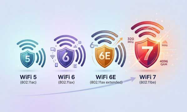
Industrial WiFi continues to evolve with 802.11ax (WiFi 6) and the emerging 802.11be (WiFi 7), but the fundamentals — RF physics, interference management, and deployment discipline — remain the same. Engineers who master these fundamentals will consistently deliver reliable long-range wireless links in the most demanding industrial environments.
Frequently Asked Questions (FAQ)
+
Under line-of-sight conditions with a 2.4 GHz industrial module running at +28 dBm transmit power and an 18 dBi directional antenna on both ends, reliable links up to 3–5 km per hop are possible at 1–2 Mbps (BPSK modulation). At 802.11n HT20 MCS7 (65 Mbps), range typically drops to 400–800 m depending on antenna configuration and noise floor. For comparison, consumer modules with +16 dBm output and 2–3 dBi antennas rarely exceed 100–150 m at usable throughput.
+
Industrial modules include SAW/BAW band-pass filters (25–40 dB out-of-band rejection), low-noise amplifiers with NF under 1.5 dB, fast AGC with sub-1 μs attack time, programmable CCA thresholds, and DFS channel access. Consumer modules typically omit SAW filters (relying on PCB-integrated band-pass filtering with only 8–12 dB rejection), use LNAs with 2.5–4 dB NF, and implement only basic EDCA. In a 10 V/m interference field from a VFD at 3 m, an industrial module typically keeps PER below 5%, while a consumer module can experience 30–50% PER.
+
Typical industrial modules output +18 to +23 dBm per chain without an external FEM, and +23 to +30 dBm per chain with an integrated or external FEM. Consumer modules are typically limited to +14 to +18 dBm per chain to keep BOM costs low and use less expensive certification paths. Note that achievable power also depends on regulatory domain: FCC Part 15.247 allows up to +30 dBm conducted power in point-to-point mode, while ETSI EN 300 328 limits EIRP to +20 dBm for non-adaptive systems in the EU.
+
A 30 cm reinforced concrete wall typically causes 12–15 dB of attenuation at 2.4 GHz and 20–25 dB at 5 GHz. With two concrete walls, the total loss is 24–30 dB at 2.4 GHz and 40–50 dB at 5 GHz — making 5 GHz effectively unusable beyond two walls. For multi-wall industrial environments, 2.4 GHz is recommended, with an allowance of 12–15 dB per concrete wall in the link budget.
+
Link budget is the sum of all gains (Tx power, Tx/Rx antenna gain) minus all losses (cable loss, path loss, fade margin, implementation loss). For a 600 m 2.4 GHz link: Tx power (+28 dBm) + Tx antenna (18 dBi) − cable loss (2 dB) − FSPL (96 dB) + Rx antenna (18 dBi) − cable loss (2 dB) = −36 dBm received power. With Rx sensitivity of −75 dBm (HT20 MCS7), the link margin is 39 dB — well above the recommended 10 dB minimum.
+
Yes, but the range improvement comes mainly from OFDMA and MU-MIMO rather than higher transmit power. 802.11ax introduces OFDMA Resource Units, allowing the module to concentrate power into narrower subchannels (as narrow as 2.03 MHz for a 26-tone RU), improving SNR by 6–10 dB at low data rates compared to 802.11ac’s full-channel allocation. 802.11ax also improves receiver sensitivity by 1–3 dB through mandatory LDPC coding. In interference-heavy environments, 802.11ax modules typically show 2–4x better spectral efficiency, which translates to more stable long-range links.
+
Per IEC 61000-6-2 (the generic standard for industrial environments), modules should meet: ESD ±8 kV contact / ±15 kV air (IEC 61000-4-2 Level 4), radiated RF 10 V/m 80 MHz–1 GHz (IEC 61000-4-3 Level 3), EFT ±2 kV on supply lines (IEC 61000-4-4 Level 3), surge ±2 kV line-to-line / ±4 kV line-to-earth (IEC 61000-4-5 Level 4), conducted RF 10 V 150 kHz–80 MHz (IEC 61000-4-6 Level 3), and power-frequency magnetic field 30 A/m (IEC 61000-4-8 Level 4). Consumer modules typically test only to Level 1 or Level 2 for most immunity categories.
+
The highest-demand scenarios are: (1) Oil and gas pipeline ROW monitoring requiring 3–5 km linear hops with interference from cathodic protection rectifiers. (2) Open-pit mining with 2–5 km links between control rooms and mobile equipment operating near high-voltage shovels and haul trucks. (3) Large factory campuses (500 m+) with VFD banks, welding cells, and co-located wireless systems. (4) Underground mining tunnels where reinforced concrete causes 120–140 dB path loss over 300 m. (5) Remote well-site connectivity across 1–5 km with seasonal foliage changes and lightning-prone environments.
+
Cable loss is often underestimated. A 10 m run of RG58 coaxial cable loses 5–7 dB at 2.4 GHz and 10–14 dB at 5 GHz — enough to negate the benefit of a high-power amplifier. For runs over 3 m, use LMR-400 or equivalent low-loss cable. For 5 GHz links, keeping the cable under 1 m or mounting the module directly at the antenna feed point is recommended to preserve the link budget.
- IEC 61000-6-2:2016 — Electromagnetic compatibility (EMC) — Generic standards — Immunity for industrial environments
- FCC Part 15.247 — Operation within the bands 902–928 MHz, 2400–2483.5 MHz, and 5725–5850 MHz
- ETSI EN 300 328 V2.2.2 — Wideband transmission systems; Data transmission equipment operating in the 2.4 GHz ISM band
- IEEE Std 802.11-2020 — Wireless LAN Medium Access Control (MAC) and Physical Layer (PHY) Specifications
- Friis, H.T. (1946). “A Note on a Simple Transmission Formula.” Proceedings of the IRE, 34(5), 254–256.