Key Overview
Who this is for: Construction project managers and safety supervisors responsible for tunnel and pipeline projects where traditional wired video surveillance is impractical due to enclosed spaces, narrow work zones, and highly mobile construction equipment.
Core Issue: Tunnel and pipeline construction sites — typically 1.5 km+ in length — have no line of sight, are highly mobile, lack power infrastructure, and require real-time monitoring for worker safety. Traditional wired cameras are too slow to deploy, expensive to retrofit, and can’t support mobile equipment.
Key Conclusions: This solution deploys industrial-grade wireless bridges and mobile monitoring nodes to create a three-tier architecture (front-end monitoring, mid-range transmission, back-end control) covering the entire tunnel zone. Key metrics: 7×24 real-time video coverage with zero blind spots, seamless mobile equipment connectivity, remote access via mobile/PC, PTZ control, and video recording/playback for safety audits. All equipment is sandstorm-rated with solar power support.
Solution Background
Tunnel pipeline construction sites are defined by **enclosed environments, long and narrow spaces, highly mobile work zones, and extremely complex cabling requirements**. Traditional wired video surveillance systems come with long deployment cycles, costly retrofits, and an inability to support mobile equipment operations, making it nearly impossible to deliver the real-time, comprehensive, and flexible monitoring that modern tunnel projects demand. To ensure worker safety and improve construction management efficiency on a 1.5km tunnel project, we developed this wireless video surveillance solution. By deploying industrial-grade wireless transmission equipment to build a stable, high-performance wireless monitoring network, we enable full-visibility management across the entire jobsite.
Core Objectives
- Deliver **7×24 real-time video coverage** across the entire tunnel construction zone (both entrances, mobile equipment, and inside the tunnel) with zero blind spots;
- Support seamless mobile operations for construction vehicles, ensuring stable wireless signal transmission from moving cameras with no lag or dropped connections;
- Enable both local management at the monitoring center and remote access via mobile and PC for maximum operational flexibility;
- Provide video recording, playback, and PTZ control capabilities to support construction safety audits and incident investigations;
- Design a system that balances **practicality, cost efficiency, and scalability** while adapting to the harsh tunnel environment with minimal deployment complexity.
I. Overall System Architecture Design
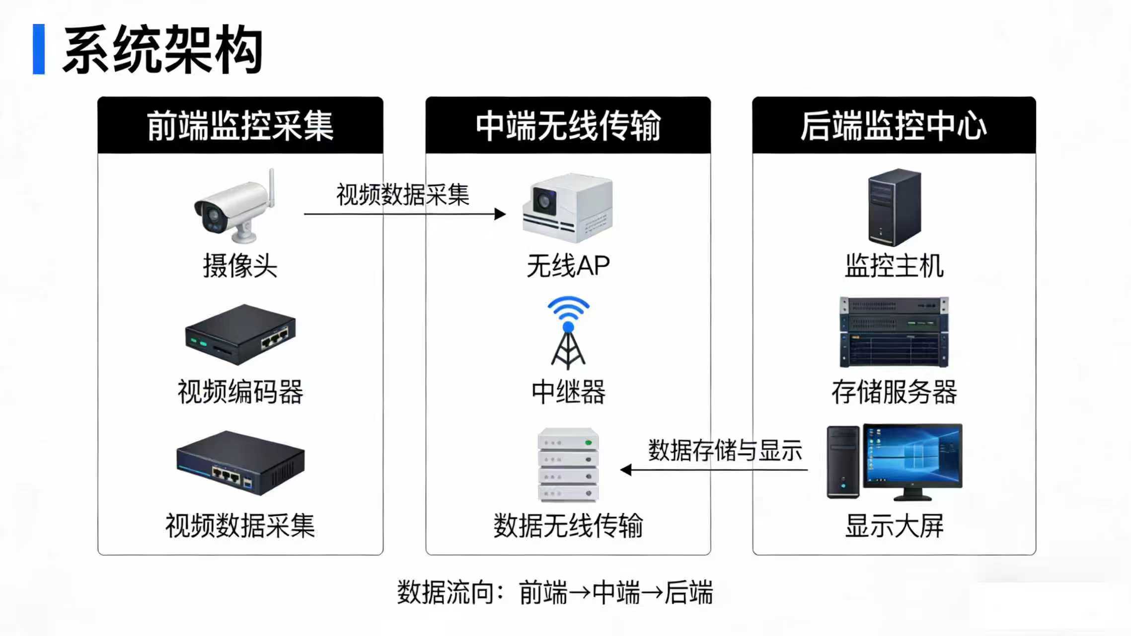
This tunnel pipeline construction wireless video surveillance system uses a **three-tier architecture**: **Front-End Monitoring & Data Collection**, **Mid-Range Wireless Transmission**, and **Back-End Data Storage & Control**. These three layers work together to form a complete closed loop — from video capture and wireless transmission through data processing, storage, and display. The overall system architecture is illustrated below:
System Architecture Diagram
II. Detailed Design and Implementation
(I) Front-End Monitoring & Data Collection
1. Monitoring Point Planning
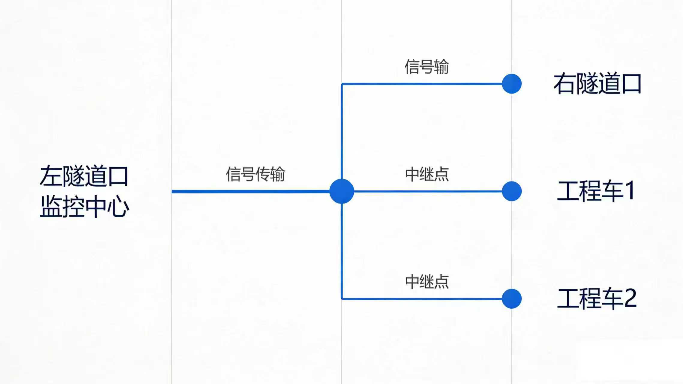
Based on the actual requirements of the 1.5km tunnel construction, we’ve planned **8 monitoring points** equipped with **7 network cameras** (some points share equipment to maximize coverage). The specific point layout is as follows:
| Monitoring Point | Equipment Configuration | Monitoring Scope & Purpose | Installation Requirements |
|---|---|---|---|
| Right Tunnel Entrance | 2 Network Cameras | Covers right tunnel entrance/exit passage and material staging area | Mounted on entrance pole, 3-5m height |
| Construction Vehicle 1 | 2 Network Cameras | Covers vehicle work face and surrounding construction area | Mounted on vehicle front/rear, shock-resistant |
| Construction Vehicle 2 | 2 Network Cameras | Covers vehicle work face and surrounding construction area | Mounted on vehicle front/rear, shock-resistant |
| Left Tunnel Entrance (Monitoring Center) | 1 Network Camera | Covers monitoring center perimeter and left tunnel entrance/exit passage | Mounted on center exterior wall, facing tunnel |
2. Equipment Selection Requirements
- Use **HD Network Cameras** with a minimum resolution of 1080P to meet detailed monitoring needs;
- Select equipment rated for **low-light, high-dust** tunnel conditions, with IR night vision and IP66 waterproof/dustproof protection;
- Vehicle-mounted cameras must be **vibration and shock-resistant** to handle mobile operation environments;
- Support PTZ control for remote adjustment of angles and focal lengths, enabling flexible monitoring coverage.
3. On-Site Implementation Considerations
- All cameras connect to the nearest switch via **Cat5e cables** routed through protective conduit to prevent damage;
- Vehicle cameras use dedicated vehicle power adapters with surge protection to ensure stable power and guard against voltage fluctuations;
- After installation, calibrate each camera’s field of view to eliminate blind spots and ensure clear, unobstructed views.
(II) Mid-Range Wireless Transmission
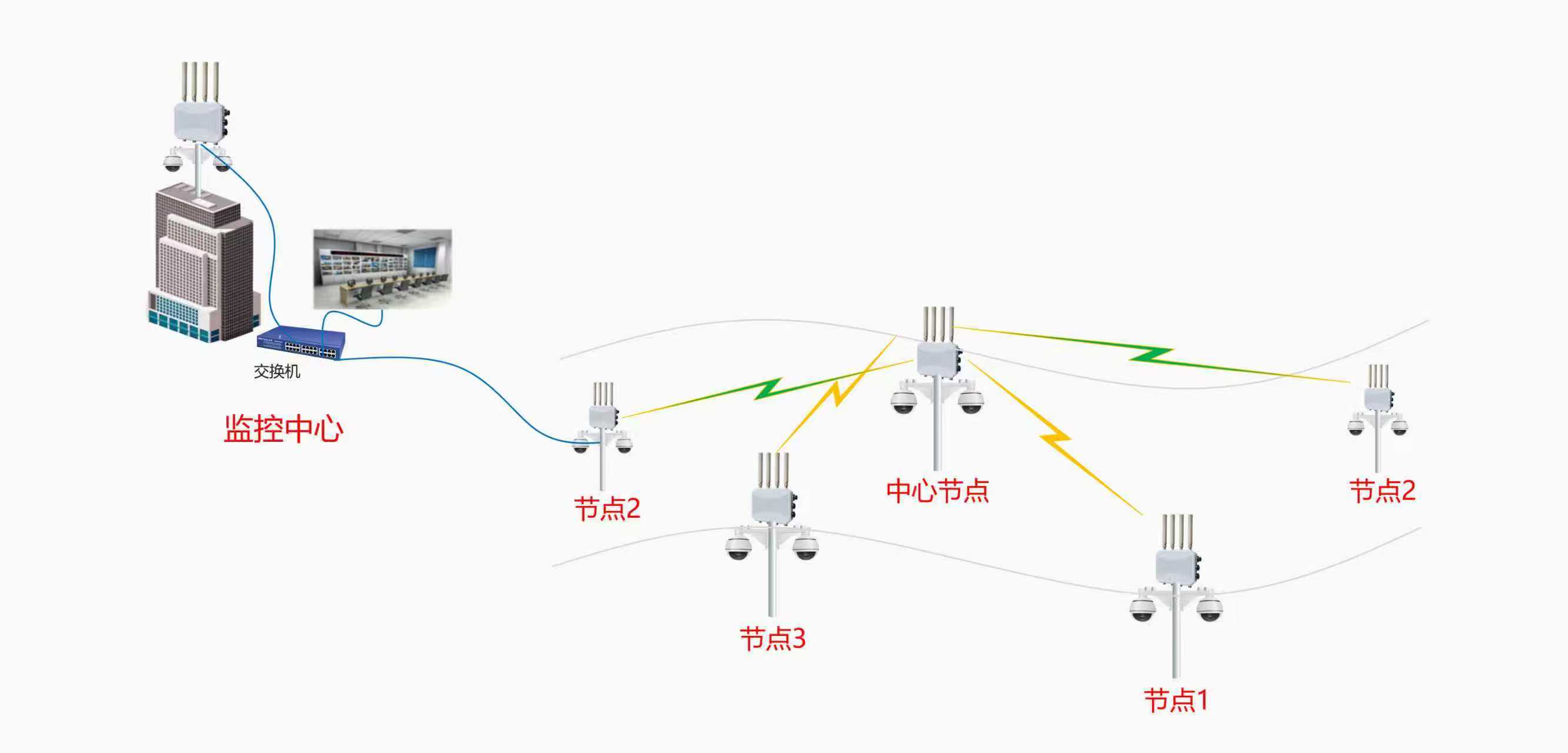
This is the core of the system, solving the challenge of non-line-of-sight (NLOS) transmission caused by tunnel curvature. We use **industrial-grade wireless bridges** as the backbone, combined with relay points to achieve signal relay transmission, ensuring consistently stable, high-speed video transmission across the entire site.
1. Core Transmission Equipment Selection
Primary equipment: **Industrial-Grade Wireless Bridge** + Omni-Directional Antenna. Key specifications and advantages:
| Equipment Parameter | Specification | Tunnel Construction Advantage |
|---|---|---|
| Operating Frequency | 5GHz | Avoids 2.4GHz civilian interference for more stable transmission |
| Transmission Technology | 2×2 MIMO | Improves signal penetration and extends transmission range |
| Max Bandwidth | 300Mbps | Handles simultaneous multi-channel HD video streams without lag |
| Design Standard | Industrial-Grade | Dustproof, waterproof, wide temperature tolerance for harsh tunnel environments |
| Antenna Type | Omni-Directional | 360° signal coverage supports mobile vehicle transmission |
2. Wireless Transmission Topology Design
Since the tunnel is not straight and the transmitter and receiver cannot maintain an unobstructed line of sight (LOS), we **deploy a relay point at the tunnel turn** using a **Transmit → Relay → Receive** configuration. The specific topology and implementation are as follows:
3. Branch Transmission Details
Branch 1: Right Tunnel Entrance Signal Transmission
- The 2 cameras at the right tunnel entrance connect to **1 Fast Ethernet Switch** via network cable for signal aggregation;
- The switch connects to **1 Wireless Bridge (Transmitter)**, which sends the signal to the relay point;
- The relay point uses **1 Wireless Bridge (Receiver)** dedicated to receiving signals from the right tunnel entrance.
Branch 2: Construction Vehicle 1 Signal Transmission
- The 2 cameras on Construction Vehicle 1 aggregate signals through the onboard switch;
- Signals feed into **1 DLB11ax Wireless Bridge + Omni-Directional Antenna (Transmitter)** for mobile transmission;
- The relay point uses **1 DLB11ax Wireless Bridge + Omni-Directional Antenna (Receiver)** to capture the mobile signal from Vehicle 1, with the omni antenna ensuring uninterrupted connectivity as the vehicle moves.
Branch 3: Construction Vehicle 2 Signal Transmission
Identical setup to Construction Vehicle 1, transmitting via **Onboard Switch + DLB11ax + Omni-Directional Antenna**, received by matching equipment at the relay point.
Relay Point Signal Aggregation & Retransmission
- The relay point aggregates signals from the 3 receiving units and connects them to **1 Core Switch** for integration;
- The core switch connects to **1 DLB11ax Wireless Bridge (Master Transmitter)**, which transmits the aggregated multi-channel video stream to the monitoring center at the left tunnel entrance.
4. Relay Point On-Site Implementation Requirements
- Position the relay point at the tunnel turn where **line of sight is relatively open**, mounted on a fixed bracket on the tunnel wall at 2.5-3m height;
- Equip the relay point with a **Weatherproof Distribution Box** housing the switch and power adapter, rated for dust, water, and impact protection;
- Power the relay point via **Tunnel Construction Dedicated Mains** with a UPS backup to ensure uninterrupted operation during power outages;
- Precisely align all wireless bridge transmitter/receiver antennas for optimal signal efficiency. After installation, verify signal strength — target no lower than -70dBm.
(III) Back-End Data Storage and Control
The Left Tunnel Entrance houses the **Core Monitoring Center**, which serves as the system’s signal control, data exchange, storage, and display hub, handling both local monitoring and remote access functions. The design and implementation are as follows:
1. Monitoring Center Equipment Configuration
| Device Name | Quantity | Function & Selection Criteria |
|---|---|---|
| Wireless Receiver | 1 Unit (DLB11ax) | Receives aggregated multi-channel video from the relay point |
| Core Switch | 1 Unit | Connects to the wireless receiver and distributes signals to the NVR and router |
| NVR | 1 Unit (16-Channel) | Central device for video signal processing, storage management, and display output; 16 channels to support all current and future monitoring points |
| Large-Capacity Hard Drive | 2 Units (4TB each, RAID backup) | Provides sufficient storage for 30+ days of continuous recording; RAID ensures data redundancy and reliability |
| Monitoring Display | 1 Unit (55-inch 4K) | Large 4K display for clear multi-channel split-screen viewing; supports 1/4/9/16 split layouts |
| Router | 1 Unit (Industrial-Grade) | Provides internet access for remote viewing; industrial-grade for 7×24 stable operation |
2. Monitoring Center Signal Flow
- The wireless receiver captures the aggregated multi-channel video signal transmitted from the relay point;
- The core switch routes the received video signal to the NVR for processing and storage;
- The NVR connects to large-capacity hard drives for video storage and simultaneously outputs feeds to the monitoring display;
- The router connects the NVR to the internet, enabling remote access functionality.
3. Core Feature Implementation
The monitoring center supports **Local Operations + Remote Access**, covering the full range of construction monitoring scenarios. Specific features include:
| Feature Module | Description | Operation Method |
|---|---|---|
| Real-Time Video Monitoring | Displays up to 8 channels simultaneously; supports 1/4/9 split-screen switching with smooth HD playback | Local operation via monitoring display, controlled through NVR panel |
| Recording Management | Configurable recording quality (HD/SD) and schedule (timed/24/7) per channel; supports loop recording | NVR local configuration, saveable recording rules |
| Multi-Mode Recording | Supports manual, motion-triggered, and alarm-triggered recording; overlay recording available for critical points | Triggered/configured locally or remotely |
| PTZ / Dome Control | Remote adjustment of camera angle, focus, and zoom to capture the best monitoring view | Local via control keyboard; remote via client software |
| Playback & Investigation | Search by monitoring point, time, or recording mode; supports local playback or remote download with clear forensic-quality images | NVR local search; remote client query |
| Remote Access | Accessible via PC browser (IE-based) and mobile app for real-time monitoring anytime, anywhere; feeds are synchronized with local display | Enter device unique IP / Device ID, verify credentials to access |
4. Monitoring Center On-Site Implementation Requirements
- Locate the monitoring center in a **well-ventilated, dry, easy-to-manage** area at the left tunnel entrance, with a dedicated monitoring room of at least 10m²;
- Mount all equipment in a **Standard Rack Cabinet** with proper cable management; equip the cabinet with cooling fans to maintain normal operating temperatures;
- Use a **Dedicated Power Circuit** with a UPS uninterruptible power supply to keep equipment running during unexpected outages and prevent recording loss;
- Label all cables clearly — network cables, power cables, and video cables must be tagged and numbered for easy maintenance;
- After system commissioning, provide hands-on training for construction management personnel to ensure proficiency in both local and remote operations.
III. Implementation Assurance Measures
(I) Equipment Quality Assurance
All equipment is **industrial-grade**, with no consumer-grade substitutions. Core components including wireless bridges, cameras, and NVRs carry original factory warranties of at least 1 year. Spare units are kept on hand to prevent equipment failure from disrupting system operations.
(II) Construction & Installation Assurance
- Assemble a professional installation crew with proven experience in tunnel construction monitoring systems and wireless transmission equipment tuning;
- Conduct a thorough on-site survey before construction; develop detailed installation plans and schedules with clear responsibilities for each phase;
- Follow design specifications strictly during installation, with proper equipment and cable protection to prevent construction-related damage;
- Perform full system integration testing after installation, verifying every monitoring point, transmission link, and system function to ensure fault-free operation.
(III) Power & Network Assurance
- Use a dual power scheme: **Tunnel Construction Dedicated Mains + UPS Backup Power**. Both the relay point and monitoring center are equipped with UPS units for stable power delivery;
- Operate wireless transmission on the 5GHz band to avoid civilian frequency interference. Implement channel planning for all wireless bridges to prevent co-channel conflicts;
- The monitoring center uses a **Static IP** for reliable remote access. Implement network security measures, including device access passwords to prevent unauthorized entry.
(IV) Ongoing Maintenance Assurance
- Develop a **System Daily Maintenance Manual** defining daily inspection items, frequency, and responsible personnel — covering signal strength, equipment status, and video quality checks;
- Establish a **Rapid Fault Response Protocol** staffed with dedicated maintenance technicians. Respond within 30 minutes of a fault report, with on-site resolution within 2 hours;
- Perform regular system optimization and upgrades, adjusting monitoring points and transmission parameters flexibly as construction progresses and requirements evolve;
- Maintain an equipment archive documenting installation locations, models, and warranty periods for all devices to streamline future replacements and servicing.
IV. Cost-Effectiveness Analysis
This solution uses **industrial-grade, cost-effective equipment** precisely scoped to the actual needs of tunnel construction with no unnecessary hardware. Compared to traditional wired systems, the wireless approach significantly reduces cabling costs and deployment timelines. Key advantages include:
- **Lower Installation Costs**: No long-distance network cable or fiber runs required, eliminating cable, conduit, and labor expenses. Deployment timeline is reduced by over 50%;
- **Reduced Maintenance Costs**: Fewer devices and simpler infrastructure mean lower inspection and servicing overhead, cutting ongoing operational labor costs;
- **Strong Adaptability**: Supports mobile construction vehicle operations without the need for rewiring as vehicles move. When work zones shift, equipment can be easily relocated and repurposed;
- **Built-In Scalability**: Modular design means adding new monitoring points later only requires additional cameras and wireless bridges — no system-wide overhaul needed, keeping expansion costs low.
V. Solution Summary
This Tunnel Pipeline Construction Wireless Video Surveillance Solution was purpose-built to address the **specific site conditions, operational requirements, and management pain points** of a 1.5km tunnel project. Using a three-tier architecture and industrial-grade wireless bridges with relay points, it solves the non-line-of-sight transmission challenge inherent in tunnels, delivering end-to-end coverage from front-end data collection through mid-range stable transmission to back-end centralized management.
The system strikes a strong balance between **practicality, reliability, and scalability**. It meets the core requirements of real-time surveillance, mobile monitoring, and remote access during tunnel construction, while also keeping deployment costs and ongoing maintenance manageable. With low implementation complexity, the system can be deployed quickly and put into operation with minimal delay. This solution effectively raises the bar for tunnel construction safety management, enabling visualized, intelligent oversight of the construction process and providing robust technical support for safe, efficient project execution.
Supporting Documentation Package
Management personnel operation training materials (including local and remote operation tutorials).
System equipment procurement list (including models, quantities, and reference unit pricing);
On-site construction drawings (including monitoring point layout, wireless transmission topology, and monitoring center equipment layout);
System commissioning manual and daily maintenance manual;