Monitoring & Communication Solutions for Unmanned Power Grid Construction Sites
Key Overview
Who this is for: Project managers and safety officers overseeing power grid construction in remote, uninhabited areas where cellular coverage does not exist and traditional wired monitoring is impractical.
Core Issue: Power grid construction sites in uninhabited areas face extreme weather, difficult terrain, widely scattered work points, no public network infrastructure, and highly mobile crews — making wired monitoring and communication systems infeasible.
Key Conclusions: This solution uses industrial-grade wireless bridges and mesh ad hoc networking to deploy a fully integrated monitoring and communication system that operates independently of public networks. Key deliverables: 1-5 km wireless coverage with ≥100 Mbps bandwidth, real-time HD video surveillance (1080P+), personnel GPS tracking with geo-fencing, and emergency response within 5 minutes. The system deploys in 3 days or less and operates from -40°C to +70°C.
Power grid construction in remote, uninhabited areas comes with a unique set of challenges: extreme weather, difficult terrain, widely scattered work sites, no cellular coverage, and highly mobile crews and equipment. Traditional monitoring and communication approaches simply don’t hold up — they require extensive cabling, suffer from unreliable signals and limited coverage, drive up operating costs, and create slow response times in emergencies. None of this works when you need end-to-end safety oversight, workforce coordination, equipment management, and rapid incident response. Built on industrial-grade wireless technology and tailored to real-world construction conditions in remote areas, this solution delivers a fully integrated system that combines monitoring, communication, dispatch, and emergency response. It provides visual oversight and stable connectivity across every part of the job site, throughout the entire construction lifecycle. The result is safer, more efficient power grid construction that meets the demands of even the most isolated environments — and it’s ready to deploy today.
I. Core Positioning and Objectives
(I) Core Positioning
Built on the principle of “Reliable connectivity as the foundation, visual monitoring at the core, efficient dispatch as the goal, and emergency response as the safety net,” this solution is engineered specifically for the challenges of uninhabited areas — no cellular infrastructure, rugged terrain, extreme temperature swings, and frequent sandstorms. We use industrial-grade wireless transmission equipment to deploy an integrated monitoring and communication system that operates independently of public networks. It’s flexible, quick to set up, highly resistant to interference, and simple to maintain. The system covers every phase of power grid construction — foundation excavation, tower erection, conductor stringing, equipment installation, and on-site personnel operations — giving you full visibility, always-on connectivity, coordinated dispatching, and the ability to act fast when it matters.
(II) Objectives
- Reliable Communications: Full coverage across the 1–5 km construction zone with wireless bandwidth of at least 100 Mbps. Stable signal with no lag or dropped connections. Bit error rate (BER) at or below 1%. Simultaneous support for voice dispatch, data transmission, and video streaming.
- Complete Monitoring Coverage: Every active work area is covered with no blind spots — tower erection sites, foundation digs, material yards, and crew lodging areas. Real-time HD video streaming with infrared night monitoring. Image resolution of 1080P or higher.
- Personnel Tracking: Real-time location tracking, movement history, voice calling, and geo-fencing with automatic alerts when workers enter or leave designated zones. Keeping personnel safe is the priority.
- Equipment Oversight: Real-time monitoring of construction machinery — cranes, excavators, tensioners, and more. Automatic alerts for anomalies like equipment faults or unsafe operation, plus the ability to issue dispatch commands directly to equipment operators.
- Emergency Response: Instant alarm triggers for incidents including personnel injuries, equipment failures, or sudden weather changes. Voice-linked alerts and full video playback for post-incident review. Target emergency response time: 5 minutes or less.
- Simple Operations & Maintenance: System deploys in 3 days or less per construction zone. Equipment is rated for sandstorms and temperatures from -40°C to +70°C. No need for round-the-clock on-site personnel. Fault diagnosis and resolution within 1 hour.
- Scalability: Easy to add new construction points or expand equipment as the project grows. The system integrates seamlessly with existing grid O&M platforms down the line, enabling unified management across construction and operations.
II. Overall Architecture Design
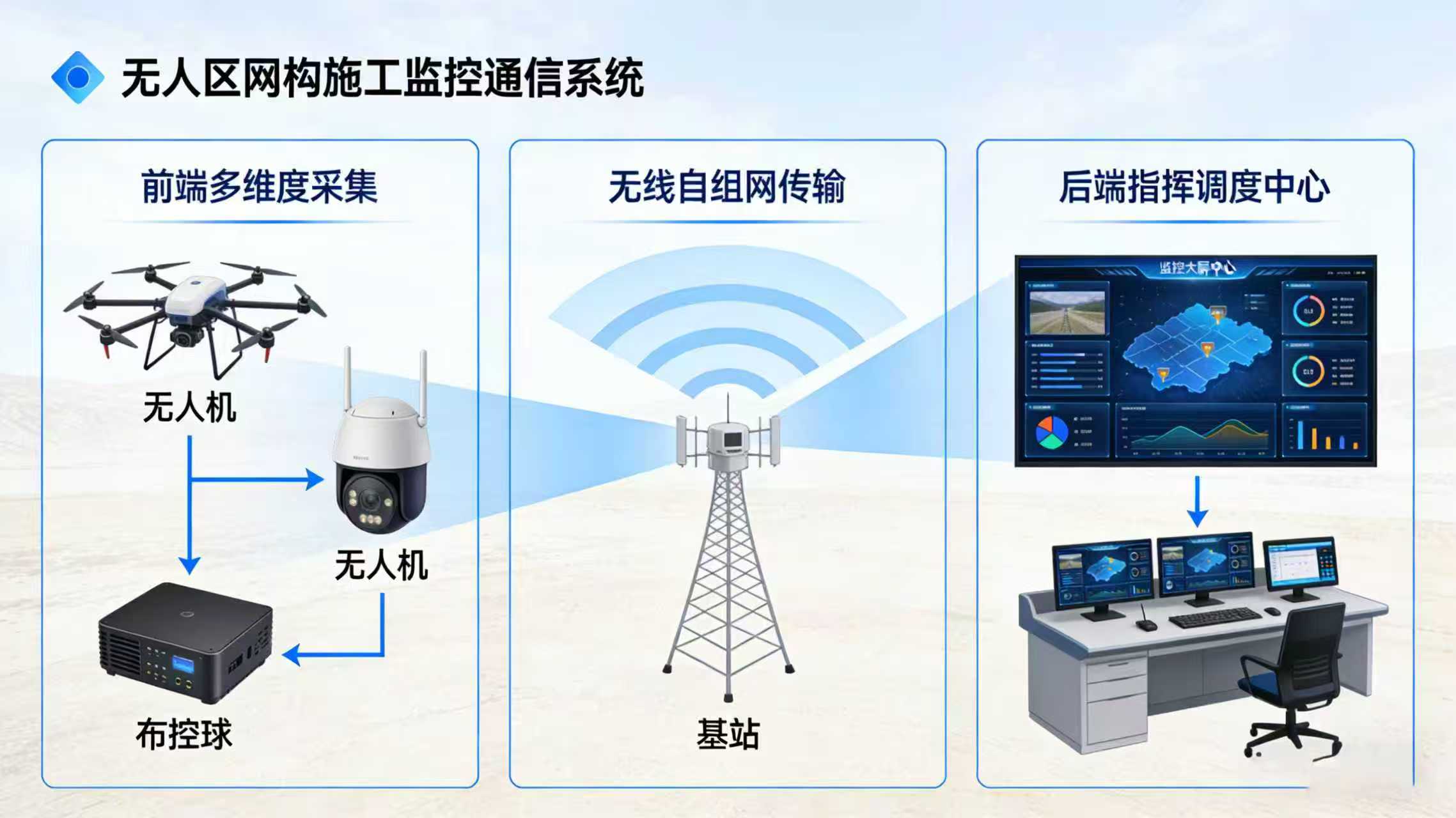
The system uses a “layered architecture with centralized control and distributed deployment” across four tiers: the front-end collection layer (monitoring and communication terminals), the mid-end transmission layer (wireless backbone network), the back-end control layer (monitoring and communications hub), and the emergency response layer (mobile and voice dispatch). These layers work together to create a closed-loop management system. The architecture is designed from the ground up to handle the realities of working without cellular coverage and with highly mobile operations in uninhabited areas. Every piece of equipment is industrial-grade, built to withstand extreme conditions. The overall system architecture is shown below:
[Image Placeholder 1: Overall Architecture Diagram of Monitoring and Communication System for Power Grid Construction in Uninhabited Areas] (Matches the style of the original link’s architecture diagram, labeling equipment at each level, data flow direction, core labels: Front-end Collection Layer, Mid-end Transmission Layer, Back-end Control Layer, Emergency Linkage Layer, clarifying equipment models and connection relationships at each layer, with a simple background color, highlighting the wireless transmission link)
Core Architecture Breakdown
1. Front-End Collection Layer: Deployed at every construction point. Responsible for capturing video, tracking personnel and equipment locations, and connecting voice terminals. Equipment is fully mobile, designed to move as construction progresses across widely scattered sites.
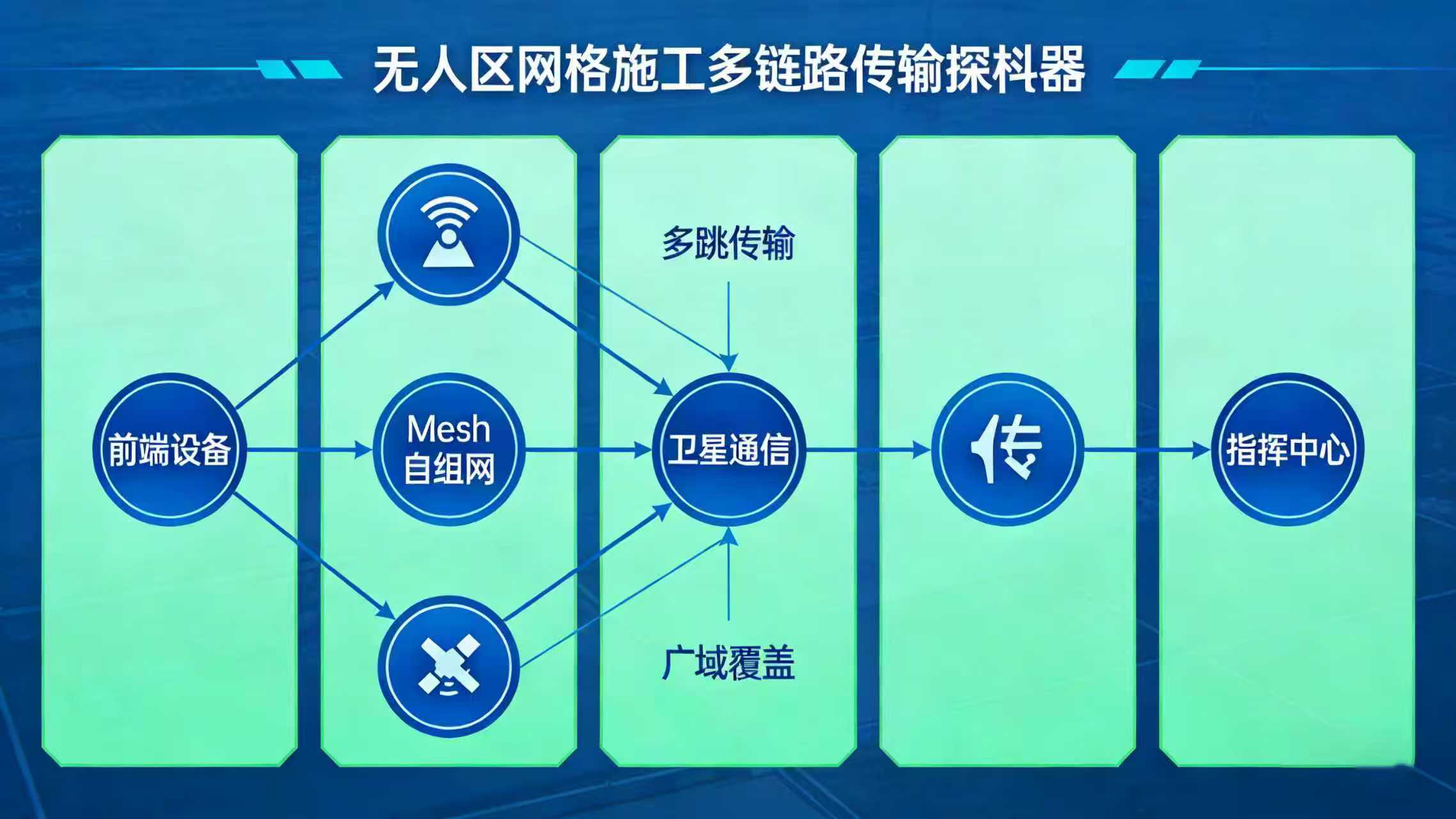
2. Mid-End Transmission Layer: The backbone of the system. Industrial-grade wireless bridges and mesh ad hoc networking equipment create a private wireless network where no public infrastructure exists. This layer handles long-distance, stable data transmission and supports multi-point signal relay to work around terrain obstructions common in remote areas.
3. Back-End Control Layer: Located in the temporary on-site command center (which is itself mobile). Responsible for video storage, display management, personnel and equipment coordination, and issuing operational commands. This is the central hub for all control functions.
4. Emergency Response Layer: Connects field personnel with the command center in real time through a mobile app and handheld two-way radios. This layer enables rapid response to incidents and removes the distance barrier between the field and decision-makers.
III. Detailed Design and Implementation by Layer
This section gets into the specifics: what equipment to use, where to put it, how to install it, and how to verify it’s working correctly. Every element has been optimized for real construction conditions in uninhabited areas, so your team can take this and run with it.
(I) Front-End Collection Layer (Flexible Deployment, Built for Harsh Conditions)
The front-end collection layer is where all your data originates, covering every critical construction point. Because work sites in uninhabited areas are spread out, highly mobile, and typically lack access to grid power, we use a “mobile deployment + solar power” approach. All equipment is industrial-grade, low-power, and sandstorm-rated. Here’s how it breaks down:
1. Site Planning (Built for Real Construction Workflows, No Blind Spots)
Based on the standard power grid construction workflow in uninhabited areas (foundation excavation → tower erection → conductor stringing → equipment acceptance), we’ve defined five types of monitoring and communication points. The specific distribution and purpose of each is outlined below:
| Point Type | Qty per 10 km Section | Deployment Location | Primary Purpose | Deployment Notes |
|---|---|---|---|---|
| Foundation Excavation | 3–5 | Each tower foundation dig site | Track excavation progress, verify build quality, monitor crew safety | Temporary setup; fully movable, no fixed location |
| Tower Erection | 2–3 per tower | Around the tower erection area (clear line of sight) | Monitor crane operations, tower plumbness, crew coordination | Temporary setup; relocated after each tower completion |
| Conductor Stringing | 4–6 | Stringing start/end points and intermediate crossing locations | Monitor stringing progress, protect crossing structures, oversee crew | Mix of fixed and mobile; temporary at crossing points |
| Material Storage | 1 | Central material yard (near temporary command center) | Monitor material security, track check-in/check-out, prevent theft | Fixed deployment for the duration of the project |
| Temporary Command Center | 1 | Central to the construction zone (reasonably accessible) | Centralized control, crew dispatch, emergency management | Fixed deployment; serves as the system’s core hub |
2. Core Equipment Selection (Industrial-Grade, Built for Remote Environments)
All equipment is selected for sandstorm resistance, wide temperature tolerance, waterproof/dustproof construction (IP67 or better), and low power draw — with no dependency on grid power. Details below:
(1) Monitoring Equipment
| Equipment | Recommended Model | Specifications | Why This Works for Remote Areas | Installation Requirements |
|---|---|---|---|---|
| HD IR Network Camera | Industrial-Grade HD PTZ (Mesh-Compatible) | 1080P resolution, IR night vision up to 50m, PTZ control, motion detection, IP67 rated, low power consumption ≤15W | Withstands sandstorms and extreme temperatures. Night vision works reliably after dark. Low power draw works with solar. PTZ covers the full work area. | Mount on a movable pole, 3–4m high, clear line of sight, aimed at the work area |
| Panoramic Camera | 360° Panoramic Network Camera | 4K resolution, 360° view with no blind spots, supports motion-triggered alerts, IP67 rated | A single unit covers the entire material yard or command center perimeter. Fewer cameras means lower maintenance. | Fixed install at center of material yard or on command center roof, clear line of sight |
(2) Communication and Positioning Equipment
| Equipment Name | Selection Model (Reference Original Link) | Configuration Parameters | Advantages for Remote Areas | Deployment Requirements |
|---|---|---|---|---|
| Industrial Wireless Bridge | ZU-KAKA Industrial-Grade Wireless Bridge (ZK-5800 Series) | Transmission distance 1–5 km (up to 10 km with booster), bandwidth ≥100 Mbps, operating temperature -40°C ~ +70°C, IP67 rated, supports PoE power supply | Cellular-free long-distance transmission. Stable signal in sandstorms and extreme temperatures. PoE eliminates need for separate power lines. Easy relocation for mobile work sites. | Mount on 3–5m pole or high ground, clear line of sight between bridge pairs. Relay deployment for obstructed terrain. |
| Mesh Self-Organizing Network Node | ZU-KAKA Mesh Ad Hoc Node (ZK-Mesh Series) | Multi-hop self-healing network, single-hop transmission up to 1 km, bandwidth ≥50 Mbps, supports automatic topology discovery, IP67 rated, low power consumption | Self-healing mesh keeps the network up even if individual nodes fail. Nodes can be dynamically added or removed. Ideal for scattered, mobile construction points. | Deploy at construction points and along transmission paths. Nodes automatically discover each other and form the network. |
| Handheld Positioning Terminal | Industrial-Grade Rugged PDA with GPS/Beidou | GPS + Beidou dual-mode positioning, positioning accuracy ≤5m, supports voice calls, video calls, geo-fencing, IP68 rated, battery life ≥12 hours | Dual-mode satellite positioning works reliably in remote areas. Rugged build handles drops, dust, and water. Long battery life for full-shift field use. | Issued to all field personnel. Connects to the command center via the mesh network. |
| Smart Helmet | ZU-KAKA Smart Safety Helmet (ZK-Helmet Series) | Built-in HD camera (1080P), supports voice intercom, one-touch SOS, GPS positioning, fall detection, collision warning, battery life ≥8 hours | First-person video gives command center a real-time view from the worker’s perspective. SOS and fall detection are critical for lone workers in hazardous terrain. | Worn by field workers, especially those working at height or alone. |
(3) Power Supply Equipment
| Equipment Name | Selection Model (Reference Original Link) | Configuration Parameters | Advantages for Remote Areas | Deployment Requirements |
|---|---|---|---|---|
| Solar Power System | Foldable Solar Panel + Lithium Battery + MPPT Controller | Panel power ≥200W, battery capacity ≥60Ah, supports continuous operation for 3+ days without sun, supports simultaneous camera + bridge power supply | True off-grid power: no generator, no fuel, no grid connection. Portable and easy to relocate. | Position panels facing south, keep surfaces clean. Battery box should be waterproof. |
3. Front-End Installation and Commissioning Standards
Installation Requirements:
(1) Camera Installation: Pole height 3–5m (adjust based on terrain). The bracket must be firmly guyed with wind ropes to handle sandstorms. The camera’s field of view should cover the entire work area with no obstructions. Night vision must be tested on-site to ensure adequate illumination at the maximum operating distance.
(2) Wireless Bridge Installation: Bridges at both ends must have a clear line of sight. If the path is obstructed (hills, structures, etc.), set up a relay point on high ground. The antenna should use a pole mount at 5m+. Ensure the bridge is well-sealed and waterproof.
(3) Solar Power Installation: Position the panel for maximum sun exposure (typically facing south). Secure the bracket against wind. The battery box must be waterproof and placed in a shaded area to prevent overheating. Cables should be protected against animals (rodents, etc.).
(4) Commissioning Verification: Verify that the camera image is clear with correct PTZ operation. Confirm the wireless bridge signal strength (RSSI ≥ -65dBm) and bandwidth meets standards. Validate that the mesh network is self-organizing and the video can be accessed from the back-end control layer.
(II) Mid-End Transmission Layer (Long-Distance Wireless Backbone That Handles Obstructions)
The mid-end transmission layer is the backbone of the entire system. In environments with zero cellular infrastructure, it handles the long-distance, high-bandwidth, low-latency relay of video, positioning data, and voice from every front-end collection point back to the command center. It also supports multi-hop relay to work around terrain obstructions.
Transmission Route Planning:
Two network architectures are used depending on the terrain:
| Architecture Type | Applicable Scenario | Core Equipment | Architecture Features | Deployment Method |
|---|---|---|---|---|
| Point-to-Point / Point-to-Multipoint (Star) | Open terrain with clear line of sight between the command center and construction points | Industrial wireless bridge | Simple structure, high bandwidth (≥100 Mbps per link), low latency. Suitable for relatively concentrated point distribution. | Central bridge at command center + directional bridge at each point. Align antenna for maximum signal. |
| Mesh Multi-Hop (Ad Hoc Network) | Complex terrain with obstructions (hills, valleys). Points are widely scattered without direct line of sight. | Mesh ad hoc node | Self-organizing, self-healing network. Nodes relay data through neighboring nodes to bypass obstructions. Supports dynamic node addition/removal. | Deploy nodes at each point. Nodes form the network automatically. Add relay nodes on high ground as needed. |
Core Equipment Selection:
(1) Industrial Wireless Bridge (ZK-5800 Series): Long-distance, high-bandwidth backbone for main transmission routes. Supports PoE for simplified power. Can cover 1–5 km under normal conditions and up to 10 km with a signal booster.
(2) Mesh Ad Hoc Node (ZK-Mesh Series): Self-organizing backup and extension network. Each hop covers up to 1 km with bandwidth ≥50 Mbps. Ideal for complex terrain where line of sight is not possible.
Installation and Commissioning:
(1) Bridge Installation: Antenna at 5m+ height with clear line of sight. Use the strongest available encryption (WPA2-AES). After installation, verify RSSI ≥ -65dBm and throughput ≥80 Mbps.
(2) Mesh Node Installation: Node at 3m+ height with as wide a sky view as possible. After installation, verify that the mesh topology map shows all nodes online and connected. Test video relay quality by streaming from the farthest node.
(III) Back-End Control Layer (Centralized Command and Dispatch)
The back-end control layer is the nerve center. All video feeds from the front-end, all personnel location data, and all voice communications converge here. Operators use this layer to oversee the entire construction zone, manage resources, coordinate crews, and respond to events. It runs entirely on the private wireless network, independent of public infrastructure.
1. Command Center Setup
The command center is typically set up in a mobile shelter (prefabricated container or vehicle) located near the construction zone for the duration of the project. Core equipment required:
| Equipment | Qty | Specification | Purpose |
|---|---|---|---|
| NVR (Network Video Recorder) | 1 | 16-channel, H.265, 8TB HDD, supports 30-day continuous recording | Video storage and playback. H.265 saves storage. 8TB covers a month of footage from 8–10 cameras. |
| Management Workstation | 1–2 | Business-grade PC, dual monitors, dedicated graphics | Used by dispatchers to manage live video, personnel tracking, and dispatch communications. |
| Large Display | 1 | 55″ industrial LCD, 4K resolution | Central video wall for real-time viewing of all camera feeds. |
| Central Switch | 1 | Industrial-grade, 24-port, PoE+, managed VLAN L2+ | Central network hub connecting all command center equipment. VLAN support for separating video, voice, and data traffic. |
| Dispatch Phone / VoIP Gateway | 1 | VoIP gateway supporting SIP protocol, connects to handheld radios and intercoms | Enables voice dispatch from command center to all field personnel over the private network. |
2. Video Management System (VMS) Software
The VMS runs on the management workstation and provides:
(1) Live View & Playback: View all cameras in grid or full-screen modes. Time-based search and playback for incident review.
(2) Motion Detection & Alarms: Configure motion zones on any camera. System automatically triggers an alarm (screen pop-up, audible alert) when motion is detected in a defined area, such as a restricted zone or material storage yard.
(3) GIS Mapping Integration: Personnel locations from GPS/Beidou terminals are plotted on a map in real time. Click on any worker to see their name, assignment, and current location. Historical tracks show movement patterns for safety audits.
(4) Two-Way Voice Intercom: Operators can initiate a voice call with any field personnel directly from the VMS interface. Calls are routed over the private wireless network.
3. Backup and Redundancy
(1) Satellite Backup Terminal (optional but recommended for extreme remote areas): For sites where the risk of complete wireless backbone failure is unacceptable (e.g., a significant natural disaster), a satellite terminal can provide a low-bandwidth emergency link. This ensures at minimum that voice dispatch and SOS alerts remain operational even if the primary network goes down.
(2) NVR RAID Configuration: The NVR supports RAID 1 or RAID 5. This protects against hard drive failure by mirroring or striping data across multiple drives.
(IV) Emergency Response Layer (Fast Action When It Matters Most)
The emergency response layer connects the command center with field personnel through the mobile app and two-way radio system, ensuring that help can reach anyone, anywhere in the construction zone, within minutes. This layer is designed to work independently of public cellular networks and be operational from day one.
1. Mobile App (Installed on Handheld Terminals)
Every field worker carries a handheld terminal with the dispatch app installed. The app provides:
(1) One-Touch SOS: A large, prominent button on the app home screen. When pressed, it immediately sends an alert with the worker’s GPS location to the command center. The command center operator receives a pop-up alert with the worker’s identity, location, and a timestamp. Voice communication is automatically established.
(2) Voice Dispatch: Workers can initiate or receive voice calls with the command center or with other workers (group or individual). All voice is transmitted over the private wireless network.
(3) Job Site Map: A real-time map showing the worker’s own location and the locations of nearby crew members. This helps workers maintain situational awareness and avoid entering dangerous areas.
(4) Alarm Acknowledgement: When the command center broadcasts an emergency alert (e.g., severe weather warning, evacuation order), workers must acknowledge receipt. The system tracks who has acknowledged and who has not.
2. Voice Dispatch System
The voice dispatch system is built around the VoIP gateway at the command center and the two-way radio functionality embedded in the handheld terminals. Key capabilities:
(1) Group Call: Dispatch to all workers in a zone or across the entire site. Used for general announcements, shift changes, or emergency broadcasts.
(2) Private Call: One-on-one communication between the command center and a specific worker, or between two workers.
(3) Emergency Priority: SOS calls automatically preempt any ongoing non-emergency communication. The command center sees the emergency caller’s location and video feed (if using a smart helmet) on screen.
3. Alarm and Event Management Workflow
The following table defines the key alarm types, their triggers, response workflows, and targets:
| Alarm Type | Trigger Condition | Response Workflow | Target Response Time |
|---|---|---|---|
| Personnel Injury / SOS | Worker presses SOS button, or fall detection triggered by smart helmet | 1. Command center receives alert with location and worker ID. 2. Operator calls the worker to assess situation. 3. If no response, dispatch nearest crew to the location. 4. Log incident with video evidence. | Alert to operator: ≤5 seconds. First responder dispatched: ≤2 minutes. |
| Geo-Fence Breach | Worker enters a restricted area (e.g., active crane radius, high-voltage zone) | 1. System alerts the worker with an audible warning on their terminal. 2. Command center receives an alert with the worker’s location. 3. Operator broadcasts voice warning and directs worker to leave the area. 4. Record incident. | Worker warned: ≤3 seconds. Operator notified: ≤5 seconds. |
| Equipment Fault | Camera offline, bridge signal quality below threshold (RSSI < -75dBm), solar battery low | 1. System logs the fault and displays it on the command center dashboard. 2. Operator assesses severity. 3. For critical faults (bridge offline), dispatch technician immediately. 4. For non-critical (battery low), schedule maintenance. | Fault displayed: ≤10 seconds. Technician dispatched: ≤30 minutes for critical faults. |
| Weather Alert | Sudden wind speed > Level 6 (≥50 km/h), sandstorm detected by visibility sensor (optional add-on) | 1. Command center triggers broadcast alert to all workers. 2. Workers receive voice and text alert: “Evacuate high-altitude positions immediately.” 3. System tracks worker acknowledgements. 4. Operations resume only after all-clear from command center. | Alert broadcast: ≤5 seconds. Zone evacuation confirmed: ≤10 minutes. |
IV. Budget Estimation and ROI Analysis
The table below provides a reference budget for deploying the system on one 10 km construction section (representative of a typical power grid construction project in an uninhabited area). Actual costs will vary based on specific site conditions, equipment availability, and deployment complexity. The ROI analysis highlights the primary cost savings and risk mitigation benefits that make this investment worthwhile.
Reference Budget (Per 10 km Construction Section)
| Category | Item | Qty | Unit Price (USD) | Total (USD) |
|---|---|---|---|---|
| Equipment | HD IR PTZ Camera (1080P, IP67) | 10 | $450 | $4,500 |
| Industrial Wireless Bridge (ZK-5800) | 6 | $800 | $4,800 | |
| Mesh Ad Hoc Node (ZK-Mesh) | 8 | $600 | $4,800 | |
| Handheld Terminal (GPS/Beidou) | 20 | $350 | $7,000 | |
| Smart Helmet (ZK-Helmet) | 10 | $550 | $5,500 | |
| Infrastructure | Solar Power System (200W + 60Ah) | 10 | $500 | $5,000 |
| Mounting Poles & Brackets | 10 | $150 | $1,500 | |
| Command Center Setup (NVR, display, switch, VoIP) | 1 | $5,000 | $5,000 | |
| Installation & Commissioning | Engineering & Field Deployment (2-person team, 3 days) | 6 | $400 | $2,400 |
| Total Estimated Cost | $40,500 | |||
ROI Analysis
The initial investment of approximately $40,500 per 10 km section is recovered through a combination of direct cost savings and risk reduction. Here are the primary factors:
(1) Reduced Safety Incidents: By equipping every worker with a smart helmet and positioning terminal, and by maintaining continuous monitoring, the system lowers the probability of serious safety incidents. Even one prevented fatality or lost-time injury can represent savings of $500,000 to $1M+ in direct and indirect costs (medical, legal, project delay, reputation).
(2) Eliminated Cellular Costs: No monthly cellular data plans for field communications. The private wireless network carries video, voice, and data with zero recurring cellular fees. Annual savings of $5,000 to $10,000+ per section compared to cellular-based alternatives.
(3) Faster Incident Resolution: Emergency response time drops from potentially hours (traveling to remote locations to assess) to under 5 minutes with targeted dispatch. Less downtime means more productive construction days.
(4) Reduced Equipment Loss and Theft: Continuous video monitoring and geo-fencing of material storage yards reduces theft and vandalism, which can cost $10,000 to $50,000+ per incident on a remote construction site.
(5) Lower Travel and Logistics Costs: Remote site inspections are reduced because the command center can monitor conditions remotely. Each avoided site visit saves travel time, fuel, and vehicle costs.
Estimated Payback Period: 3 to 6 months — based on conservative assumptions about incident reduction and operational savings. After the payback period, the system continues to deliver value through reduced risk and improved project efficiency.