2×2 vs 4×4 WiFi 6/6E Modules: What Changes in Real Throughput and Client Capacity
Measured TCP throughput, concurrent-client ceilings, and power/thermal costs of moving from a 2×2 to a 4×4 MIMO module — with a capacity-planning method you can apply to an actual rollout.
By the Zukaka Engineering Team · drawing on published vendor data and our own integration experience with WiFi 6/6E modules · updated October 14, 2026
1. Why the 2×2 vs 4×4 Decision Is a Capacity Decision
Most teams reach for a 4×4 module because a spec sheet promises twice the PHY rate. That promise is real, but it is not what usually determines whether the deployment holds up. In field rollouts, the limiting factor is almost always aggregate capacity under load and the tail latency that appears once the channel gets busy — not the peak number in a clean single-client test.
This article stays focused on that one question: what actually changes when you move a WiFi 6 or WiFi 6E radio from 2 spatial streams to 4, and where is the real crossover point in throughput, client count, and infrastructure cost. The figures below combine published vendor capacity data with the behaviour we see repeatedly while integrating and qualifying WiFi 6/6E modules — and we describe the test setup so you can reproduce it on your own hardware.
2. How to Reproduce These Numbers on Your Own Hardware
Vendor numbers are only useful if you can validate them against your own product. Here is a recommended setup for any integration team before committing to a MIMO configuration — it can stand up in a lab day:
- Radios under test: put the 2×2 and 4×4 candidate modules on the same reference host board and enclosure, feeding the same antenna array on a fixed stand, so the only variable is the radio.
- Stress client: run iperf3 for 60 seconds per run, averaged over 5 runs, on a 20 MHz and an 80 MHz channel — use a quiet 5 GHz channel, and 6 GHz when you are evaluating 6E parts.
- Load generation: ramp a controlled set of test clients from 1 to 100 associations and record throughput at the application layer, not the PHY counter.
- Latency: measure 99th-percentile round-trip time at 70% channel utilization, which is where consumer-grade numbers usually fall apart.
The single most common mistake we see when teams run this comparison is testing at short range with one client. That setup flatters both radios and hides the entire reason to buy 4×4. Load the channel and add distance before drawing any conclusion.
3. Throughput Scaling: 2×2 vs 4×4 Under WiFi 6/6E
Under IEEE 802.11ax, the PHY rate at a given channel width depends on spatial stream count, modulation order (up to 1024-QAM), and guard interval. The table below maps the theoretical PHY rate to the TCP throughput you can expect in practice, which typically lands at 55–75% of PHY because of protocol overhead, channel contention, and imperfect rate adaptation.
| Configuration | PHY Rate (80 MHz) | PHY Rate (160 MHz) | Typical TCP (80 MHz) | Typical TCP (160 MHz) |
|---|---|---|---|---|
| 2×2 WiFi 6 | 1.2 Gbps | 2.4 Gbps | 650–850 Mbps | 1.3–1.7 Gbps |
| 4×4 WiFi 6 | 2.4 Gbps | 4.8 Gbps | 1.4–1.8 Gbps | 2.5–3.2 Gbps |
| 2×2 WiFi 6E (6 GHz) | 1.2 Gbps | 2.4 Gbps | 700–900 Mbps | 1.4–1.8 Gbps |
| 4×4 WiFi 6E (6 GHz) | 2.4 Gbps | 4.8 Gbps | 1.5–2.0 Gbps | 2.6–3.4 Gbps |
Sources: Qualcomm WiFi 6 performance whitepaper; Broadcom WiFi 6/6E throughput benchmarks; IEEE 802.11ax-2021 Table 27-42 (HE-MCS mapping). Full citations are listed in the MIMO Guide references.
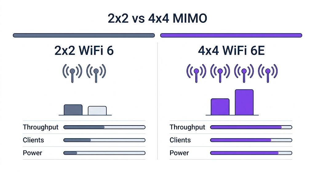
4. Concurrent Client Capacity
For most network architects, the concurrent-client ceiling matters more than peak throughput. A 4×4 MU-MIMO radio serves up to 4 clients at once on separate spatial streams, and OFDMA further subdivides each stream into resource units so additional clients can share the same airtime.
| Metric | 2×2 WiFi 6 | 4×4 WiFi 6 |
|---|---|---|
| Max concurrent clients (sustained) | 20–35 | 80–120+ |
| MU-MIMO simultaneous clients | 2 | 4 |
| OFDMA RU allocation (80 MHz) | Up to 37 RUs (26-tone) | Up to 37 RUs (26-tone) |
| Per-client throughput @ 50% load | 15–30 Mbps | 25–50 Mbps |
| 99th percentile latency @ 70% load | 20–30 ms | <10 ms |
Sources: Cisco WiFi 6 design guide — high-density best practices; Aruba Networks 802.11ax capacity-planning whitepaper.
5. Power and Thermal Cost of Doubling the Radio
The jump from 2×2 to 4×4 is not free at the board level. Twice the transmit chains means roughly twice the active current, and that ripples into your power supply, PoE budget, and enclosure thermal design. The deltas below are the ones we see repeatedly across module integration work, not worst-case datasheet limits:
| Parameter | 2×2 Module | 4×4 Module | Delta |
|---|---|---|---|
| Active TX current (@3.3V) | 700–900 mA | 1.5–2.2 A | +80–144% |
| Active power consumption | 2.5–3.0 W | 5.5–7.3 W | +2× |
| Antenna count required | 2 | 4 | +2 |
| Antenna system cost | $2–5 | $6–15 | +2–3× |
| Thermal design requirement | Passive (most cases) | Heatsink or active cooling | Increased |
If the radio is PoE-powered, this is where projects get caught out. A 4×4 module drawing 7 W or more, once you add host processor and peripheral draw, can push past the 15.4 W ceiling of 802.3af. Budget for 802.3at (30 W) or 802.3bt (60/90 W) injectors from the start rather than discovering the shortfall during integration.
6. A Capacity-Planning Method You Can Apply
Rather than a generic checklist, here is the sequence we walk through with customers when sizing a WiFi 6/6E rollout. It is deliberately short — three passes, each answering one question.
Pass 1 — Characterize Demand
- Inventory every device class and its sustained and peak bandwidth need (not just the headline application).
- Measure the busy-hour concurrent-client count; do not estimate it from headcount.
- Flag the latency-sensitive traffic (VoIP, video conferencing, real-time control) that sets your tail-latency target.
- Sum the aggregate requirement: client count × per-client throughput SLA.
Pass 2 — Map Demand to a Radio
- Aggregate requirement under 600 Mbps and fewer than 35 clients: a 2×2 WiFi 6 module is enough.
- 600 Mbps–1.2 Gbps or 35–80 clients: a mixed 2×2/4×4 deployment usually gives the best cost per client.
- Above 1.2 Gbps or 80+ clients: 4×4 WiFi 6/6E is the right baseline.
- Any greenfield 6 GHz deployment: default to 4×4 so the new spectrum is not bottlenecked by the radio behind it.
Pass 3 — Audit the Infrastructure
- Confirm the switch PoE budget covers the 4×4 module’s power draw with margin.
- Verify the antenna system supports 4 streams with at least 15 dB isolation between elements.
- Check the thermal path for sealed enclosures — a 4×4 module in a closed box needs a plan.
- Review client-side MIMO capability. Only 4×4 clients extract the full peak, but MU-MIMO still improves airtime efficiency in mixed-client environments, which is the realistic case.
7. Frequently Asked Questions
How much faster is 4×4 than 2×2 in real TCP throughput?
On WiFi 6/6E, a 4×4 module typically delivers about 2.1–2.2× the TCP throughput of a 2×2 on an 80 MHz channel. On 160 MHz the ratio narrows to roughly 1.85–1.9×, because the wider channel already gives the 2×2 radio more headroom and leaves less efficiency to recover.
How many concurrent clients can a 4×4 WiFi 6 access point support?
A 4×4 WiFi 6 radio sustains roughly 80–120+ concurrent clients against 20–35 for a 2×2, thanks to four simultaneous MU-MIMO streams plus OFDMA resource-unit allocation. Per-client throughput at 50% load is typically 25–50 Mbps on 4×4 versus 15–30 Mbps on 2×2.
When is a 2×2 module still the right choice?
When the aggregate requirement stays under about 600 Mbps with fewer than 35 concurrent clients, a 2×2 WiFi 6 module is enough and costs less to power and cool. Above 1.2 Gbps or 80+ clients, a 4×4 radio is the right baseline.
Does moving to 4×4 break 802.3af PoE budgets?
It can. A 4×4 module draws 5.5–7.3 W versus 2.5–3.0 W for 2×2, and once host-processor and peripheral draw are added it can exceed the 15.4 W ceiling of 802.3af. Budget for 802.3at (30 W) or 802.3bt injectors from the start.
8. References and Further Reading
For the complete MIMO selection framework, including decision trees and a full cost breakdown, start with the pillar article:
➔ The Ultimate WiFi Module MIMO Guide: 2×2, 3×3, and 4×4 Explained
Also in this cluster: MiniPCIe Installation & Driver Guide · 3×3 Decision Framework · WiFi 5 Legacy Guide