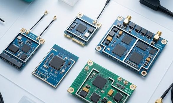
MiniPCIe WiFi Module Installation, Driver Deployment & MIMO Troubleshooting Guide
A hands-on operational reference for engineers integrating 2×2 and 3×3 MIMO MiniPCIe modules into embedded systems, industrial gateways, and custom router boards.
1. MiniPCIe Form Factor Overview
The MiniPCIe form factor (30.00 mm × 50.95 mm, 52-pin edge connector, Key B) remains the most widely adopted interface for industrial WiFi modules. Unlike M.2, MiniPCIe offers robust mechanical retention, standardized PCIe x1 lane routing, and broad BIOS/UEFI compatibility across industrial single-board computers from Advantech, Compulab, Aaeon, and Compex WPJ-series platforms.
Physical Identification
- Full-size card: 30.00 × 50.95 mm — standard for most industrial modules
- Half-size card: 30.00 × 26.80 mm — used in space-constrained designs
- Key B connector: 52 pins with PCIe x1, USB 2.0, and I2C signaling
- Antenna ports: 2× U.FL (2×2 MIMO) or 3× U.FL (3×3 MIMO), 50Ω impedance
2. Physical Installation
Step-by-Step Installation
- Power off the host system and disconnect all power sources. MiniPCIe is not hot-swappable.
- Locate the MiniPCIe slot. Verify the slot is Key B (most industrial boards) and supports PCIe x1 lane routing.
- Insert the module at a 45-degree angle into the slot, then press down until retention clips engage on both sides.
- Connect antenna cables to the U.FL connectors. Apply steady, moderate pressure when inserting — U.FL connectors are rated for approximately 30 mating cycles. Ensure each cable is routed to the correct antenna port by label (ANT1, ANT2, ANT3 for 3×3 modules).
- Secure loose antenna cables with cable ties to prevent U.FL connector dislodging during vibration or thermal cycling.
- Power on the system and verify BIOS/UEFI detects the PCIe device.
3. Driver Deployment
Linux (Kernel 5.x / 6.x)
Most MiniPCIe WiFi chipsets have native kernel driver support. Identify the chipset first by checking the module label.
| Chipset Vendor | Kernel Driver | Minimum Kernel | Firmware Package |
|---|---|---|---|
| Qualcomm Atheros (QCA9880, QCA9882) | ath10k | 4.4+ | linux-firmware (ath10k) |
| Qualcomm (QCA6174, QCA9377) | ath10k | 4.4+ | linux-firmware (ath10k) |
| Intel (7260, 7265, 9260) | iwlwifi | 5.10+ | linux-firmware (iwlwifi) |
| Realtek (RTL8812AU, RTL8822BE) | rtw88 / rtl8xxxu | 5.2+ / 3.12+ | linux-firmware (rtlwifi) |
| MediaTek (MT7612E, MT7915E) | mt76 | 5.0+ | linux-firmware (mediatek) |
Verify driver loading after boot:
$ lspci -nn | grep -i network
$ lsmod | grep -e ath -e iwl -e rtw -e mt76
$ dmesg | grep -i firmware
MIMO Mode Verification
Check the number of active spatial streams (NSS) after connection:
$ iw dev wlan0 link
# Look for: VHT-NSS 2 (2×2 mode) or VHT-NSS 3 (3×3 mode)
Windows Driver Installation
- Qualcomm Atheros: Use ath10k Bluetooth driver for Windows 10/11 from Qualcomm support portal
- Intel: Use Intel PROSet/Wireless Software (supports Windows 10 22H2 and Windows 11 23H2+)
- Realtek: Download the Realtek WLAN Driver package specific to your chipset revision
To verify MIMO mode on Windows: check the adapter link speed — 867 Mbps indicates 2×2 VHT80, 1.3 Gbps indicates 3×3 VHT80.
4. Common Troubleshooting Scenarios
Issue 1: Module Not Detected
- Verify BIOS/UEFI: Check that the MiniPCIe slot is enabled in BIOS and not disabled by a hardware jumper.
- Check PCIe enumeration: Run lspci -nn on Linux. If the module does not appear, try reseating it.
- Verify power supply: MiniPCIe provides 3.3V only (not 5V or 12V). A 3×3 module drawing 1.5 A peak may cause voltage droop on under-specified boards.
Issue 2: Throughput Stuck at 2×2 Speeds
- AP limitation: A 3×3 module connected to a 2×2 AP will operate at 2×2 speeds. The MIMO link negotiates at the lowest common spatial stream count.
- Antenna mismatch: If only 2 of 3 antennas are connected, the module falls back to 2×2 mode. Verify all antenna ports are populated.
- Driver configuration: On ath10k, forced chain mask can cap spatial streams. Check cat /sys/kernel/debug/ieee80211/phy0/ath10k/chain_mask.
Issue 3: Intermittent Disconnection & Link Flapping
- Power saving interference: On Linux, disable power saving: iw dev wlan0 set power_save off
- U.FL intermittent contact: Gently reseat each U.FL connector. If the problem persists, replace the cable assembly.
- DFS channel radar detection: On DFS channels (52–144 on 5 GHz), the module may vacate the channel due to radar events. Switch to non-DFS channels (149–165) for testing.
Issue 4: Module Overheating & Thermal Throttling
- Symptom: Throughput drops after 10–30 minutes of operation; module surface temperature exceeds 85°C.
- Fix for 3×3 modules: The Compex WLE900VX-I (QCA9880) datasheet specifies -40 to +85°C operating range. 3×3 modules can raise internal enclosure temperature by 8–12°C over 2×2 equivalents. Use thermal pad contact between the module shield can and enclosure heatsink.
- Active cooling: For sealed outdoor enclosures with 3×3 modules, consider adding a thermally conductive chassis interface or low-speed fan.
5. Reference Case: 3×3 MiniPCIe AP Deployment
Hardware: Compex WPJ564 board with WLE900VX-I (QCA9880 3×3, 802.11ac)
Configuration: Dual-band: 2.4 GHz HT40 3×3 + 5 GHz VHT80 3×3
Environment: 200 m² open-plan office, 35–50 concurrent clients
Result: Aggregate throughput 680 Mbps downlink + 220 Mbps uplink under 35-client load. Active cooling fan added per thermal budget. The 3-stream configuration provided 40% higher aggregate throughput compared to the previous 2×2 module at the same location.
6. Further Reading
This guide focuses on operational and installation aspects of 2×2 and 3×3 MIMO modules. For comprehensive MIMO selection guidance covering throughput benchmarks, power consumption analysis, and configuration decision trees, refer to the main pillar article:
➔ The Ultimate WiFi Module MIMO Guide: 2×2, 3×3, and 4×4 Explained
Also in this cluster: When to Choose 3×3 · 2×2 vs 4×4 Bandwidth · 3×3 on 5GHz WiFi 5