Mobile Mesh Devices for Industrial Wireless Networks: Deployment Guide
Key Overview
Target Audience: Industrial network engineers, field operations personnel, emergency response teams, temporary network deployment specialists
Core Question: What is a mobile mesh network? How to deploy mobile mesh devices in industrial environments? What are the application scenarios for mesh networks?
Key Conclusion: Mobile mesh networks provide self-organizing, self-healing wireless connectivity, particularly suitable for mining, emergency response, and temporary events. Deployment requires consideration of node density, coverage range, and power management.
Mesh Network Technology Overview
A mobile mesh network is fundamentally different from conventional wireless networks because it eliminates the concept of a central access point or base station. In a traditional WiFi network (BSS — Basic Service Set), all client devices must associate with a single access point, creating a single point of failure and limiting coverage to the range of that AP. In a mesh network (IBSS — Independent Basic Service Set, or MBSS — Mesh Basic Service Set under 802.11s), every node is equivalent — each node can forward data for other nodes, dynamically discover neighbors, and optimize routing paths based on real-time link quality metrics. This architecture means that adding a new node simultaneously increases both network coverage and network capacity, a property that no centralized wireless topology can match.
The core value proposition of industrial mesh networks is their ability to maintain connectivity in environments where: physical obstacles block line-of-sight (underground mines, dense industrial facilities, urban canyons), nodes are mobile (vehicles, personnel, drones), or infrastructure is temporary (emergency response, construction sites, events). In these scenarios, mesh networks outperform traditional wireless architectures by orders of magnitude in terms of deployment speed, fault tolerance, and coverage reliability. A well-designed mesh network can achieve 99.999% availability (five-nines reliability) through path diversity — if one path degrades, traffic is automatically rerouted through alternative paths in under 50 milliseconds.
Key Characteristics of Mesh Networks — Technical Deep Dive
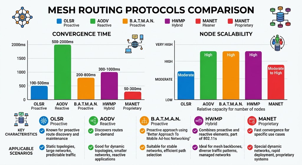
Self-organizing behavior is the foundational characteristic that enables all other mesh benefits. When a mesh node is powered on, it executes a neighbor discovery process: it broadcasts discovery frames, listens for responses from neighboring nodes, and builds a neighbor table containing link quality metrics (signal strength, packet error rate, channel utilization). This process completes in 1-5 seconds for a typical industrial mesh node. Once neighbors are discovered, the routing protocol (OLSR, AODV, B.A.T.M.A.N., or HWMP for 802.11s) calculates optimal paths through the network using metrics such as hop count, Expected Transmission Count (ETX), or airtime link metric. The routing table is continuously updated as nodes move or link quality changes, with convergence times of 100-500 milliseconds for most industrial routing protocols.
Self-healing is the automatic response to node failure or link degradation. Each mesh node continuously monitors its links to neighboring nodes by tracking packet delivery ratios and signal-to-noise ratios. When a link’s PER (Packet Error Rate) exceeds a configurable threshold (typically 20-30%), the routing protocol marks the link as degraded and recalculates alternative paths. If a node fails completely, neighboring nodes detect the absence of periodic hello messages (typically sent every 1-2 seconds) and update their routing tables within 2-5 seconds. This self-healing capability is the primary reason mesh networks are specified for mission-critical industrial applications — a 20-node mesh network with typical redundancy can tolerate up to 5-7 simultaneous node failures before any individual client experiences connectivity loss.
Multi-hop routing is what extends mesh coverage beyond the radio range of a single node. Each hop through a mesh node introduces 1-5 milliseconds of latency (depending on the routing protocol and hardware processing speed) and reduces throughput by approximately 30-50% per hop due to half-duplex radio operation and protocol overhead. This means a 5-hop mesh link will have 5-25ms additional latency and approximately 5-15% of the single-hop throughput. Understanding these performance characteristics is essential for capacity planning — video surveillance applications, for example, must ensure that no camera stream traverses more than 3-4 hops to maintain acceptable video quality.
Mesh Routing Protocols — Selection Criteria for Industrial Applications
The choice of mesh routing protocol determines the network’s performance characteristics: convergence speed, routing overhead, scalability, and mobility support. Industrial mesh applications typically use proactive protocols (OLSR, B.A.T.M.A.N.) for stable, high-performance networks, or reactive protocols (AODV, HWMP) for highly mobile or power-constrained deployments.
| Protocol | Type | Convergence Time | Scaling (Max Nodes) | Best For |
|---|---|---|---|---|
| OLSR (Optimized Link State Routing) | Proactive (table-driven) | 100-500ms | 200+ nodes | Stable industrial mesh backbones, smart city IoT, large-area coverage where topology changes infrequently |
| AODV (Ad-hoc On-Demand Distance Vector) | Reactive (on-demand) | 500-2000ms | 100+ nodes | Mobile vehicle networks, emergency response, temporary events where mobility is high and routing overhead must be minimized |
| B.A.T.M.A.N. (Better Approach to Mobile Ad-hoc Networking) | Proactive (distance-vector) | 200-800ms | 300+ nodes | Community networks, large-scale outdoor deployments, high-performance mesh requiring minimal configuration |
| 802.11s HWMP (Hybrid Wireless Mesh Protocol) | Hybrid (proactive + reactive) | 300-1000ms | 100+ nodes | WiFi-based mesh deployments, compatibility with standard WiFi infrastructure, enterprise mesh networks |
| MANET (Mobile Ad-hoc Network) custom protocols | Varies (proprietary) | 50-300ms | 50-100+ nodes | Mission-critical applications (military, mining, emergency response) requiring fastest possible convergence |
Mesh Network Topologies — Architectural Patterns
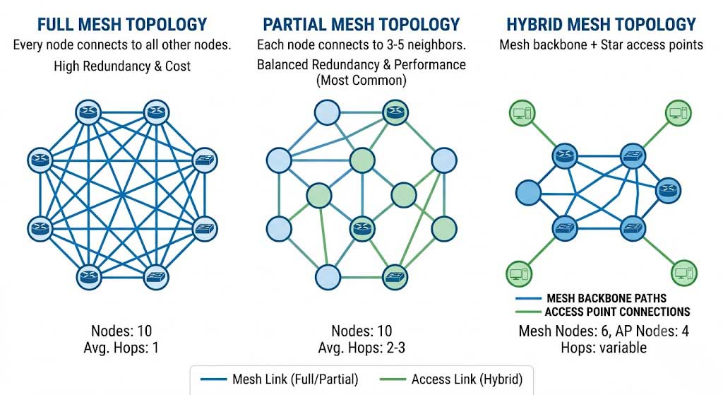
The choice of mesh topology affects redundancy, performance, and cost: full mesh provides maximum reliability but minimizes per-hop throughput, partial mesh balances reliability and throughput, and hybrid mesh combines mesh with traditional star topology for optimized performance. In a full mesh topology (n nodes, n(n-1)/2 links), the network can tolerate up to n-2 node failures before partitioning, but each node must maintain routing state for all other nodes, consuming CPU and memory resources. In practice, full mesh is only used for small clusters (under 10 nodes) in mission-critical applications. Partial mesh — where each node maintains links to 3-5 nearest neighbors — is the most common industrial configuration, providing good reliability (multiple redundant paths) with reasonable resource requirements. Hybrid mesh uses mesh connectivity for the backbone (interconnecting mesh nodes) while clients connect to mesh nodes via traditional star-topology WiFi access — this is the architecture used by most outdoor WiFi mesh deployments.
Industrial Applications of Mobile Mesh
Mining and Construction Sites — Challenging Terrain, Critical Connectivity
Mining and construction environments are among the most challenging for wireless communication due to their combination of physical obstacles (tunnel walls, excavation pits, heavy machinery), mobility (constantly changing work faces, vehicle movement), and environmental hazards (dust, vibration, extreme temperatures). Traditional WiFi architectures fail in these environments because AP-to-client line-of-sight is rarely available, mobile equipment requires frequent AP handoffs, and deploying wired backhaul to AP locations is impractical in active mining or construction areas. Mesh networks solve all three problems simultaneously: NLOS (Non-Line-of-Sight) capability through multi-hop relay, seamless mobility through routing protocol updates, and zero need for wired backhaul infrastructure.
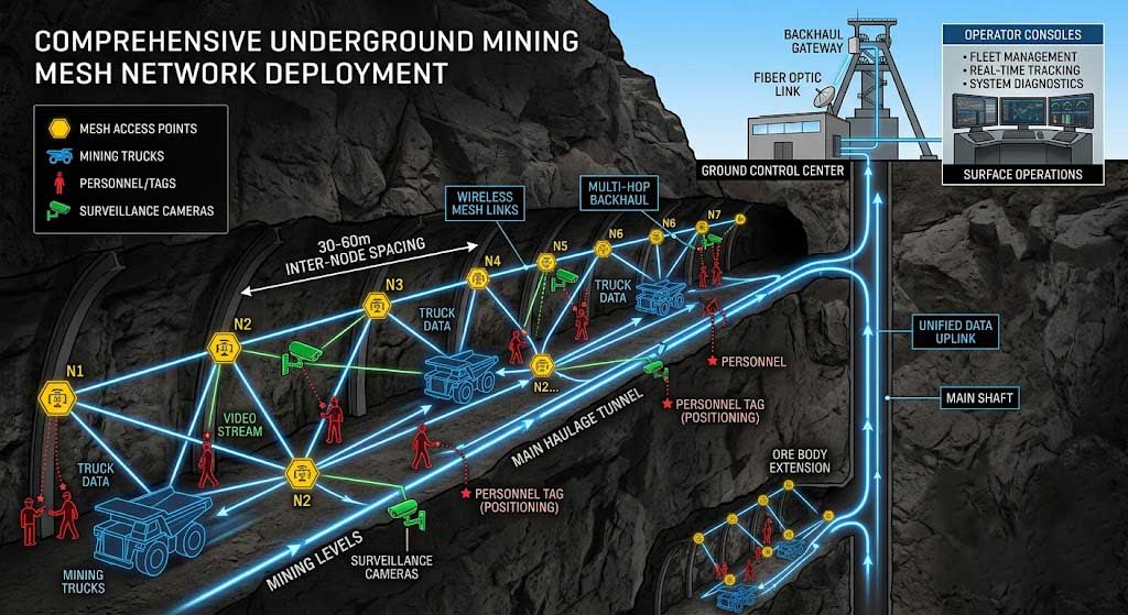
In underground mining, mesh nodes are typically deployed along tunnel walls at intervals of 30-60 meters, depending on tunnel curvature and ventilation shaft locations that can provide alternative propagation paths. Each node serves both as a relay for the mesh backbone and as an access point for mining vehicles (loaders, haul trucks, personnel carriers) and personnel with handheld devices. The mesh network must support: real-time vehicle telemetry (location, speed, fuel level, tire pressure) from 20-50 vehicles per mine, personnel tracking and safety monitoring (gas detection alerts, emergency evacuation coordination), and video surveillance of critical areas (conveyor belts, crushers, extraction points). A typical medium-sized underground mine with 30km of tunnels requires 80-120 mesh nodes to provide comprehensive coverage.
Open-pit mining presents different challenges: the pit shape creates a bowl-like topology where a central AP at the rim cannot reach equipment at the bottom of the pit. Mesh nodes are deployed around the pit perimeter and on mobile equipment, creating a cascading relay network that extends from the pit floor to the rim. Each mining truck can be equipped with a mesh client node (such as the YN300B 5.8GHz seamless roaming client) that provides 50-100 Mbps throughput while moving at speeds up to 40 km/h on haul roads. The mesh network enables remote operation of autonomous haulage systems, reducing personnel exposure to hazardous pit environments and improving operational efficiency by 15-25% through optimized haul route management.
Emergency Response Networks — The Most Demanding Deployment Scenario
Emergency response is the application that most clearly demonstrates the superiority of mesh networks over all alternative architectures because it demands: zero pre-existing infrastructure (networks must work where nothing exists), deployment speed (minutes to first communication), unpredictable coverage requirements (affected area size is unknown in advance), and extreme fault tolerance (node loss during disaster must not disrupt operations). No other wireless technology can match mesh networks across all these requirements simultaneously. Cellular networks fail when towers are damaged. Satellite systems have limited capacity and don’t work indoors. Traditional AP-based WiFi requires cabling to each AP.
The typical emergency response mesh deployment follows a systematic pattern: first-arriving units deploy portable mesh nodes at key locations (command post, triage area, logistics point), creating an initial backbone within 10-15 minutes. As additional resources arrive, more nodes are deployed forward into the affected area, extending coverage organically. Each node provides connectivity for: push-to-talk voice communication (replacing damaged two-way radio systems), real-time video from body-worn cameras and drones, situational awareness data (GPS tracking of all response personnel), and internet access (via a satellite backhaul link connected to one mesh node). The mesh protocol’s self-healing capability is critical — if a node is destroyed by fire or structural collapse, neighboring nodes automatically route around the failure within seconds.
The key technical requirement for emergency response mesh equipment is portability without sacrificing performance. Response nodes must be compact enough to be carried in a backpack (under 3kg), battery-powered for 8-12 hours of continuous operation, and operable by personnel who are not network engineers — the node must self-configure on power-up. Zukaka’s YN300C 2.4GHz Ad-Hoc Network Motherboard is designed for this use case: the 30dBm TX power provides up to 20km range in line-of-sight conditions (enabling connectivity between the incident command post and forward teams), while the Ad-Hoc self-organizing protocol eliminates the need for any network configuration or planning.
Temporary Event Networks — High-Density Coverage Without Infrastructure
Concerts, festivals, sporting events, and trade shows require wireless networks that can handle high client densities (500-2000+ devices per hectare) for short durations (1-14 days) with rapid deployment and teardown — a requirement set that makes permanent infrastructure economically impossible and mesh networks the only practical solution. A typical music festival covering 50 hectares requires 80-150 mesh nodes to provide comprehensive coverage for attendees (social media, messaging, mobile payments), operational staff (POS systems, inventory management, security communication), and broadcasting (live streaming cameras, drone video feeds).
The deployment strategy for event mesh networks differs from other applications in two important ways: node placement follows attendee density rather than area coverage, and power management must account for multi-day operation without grid connectivity. High-density areas (main stage, food vendors, entrance gates) require node spacing of 15-25 meters with each node supporting 50-100 simultaneous clients. Low-density areas (parking, camping) can use 50-100 meter spacing. Power is typically provided by battery packs for smaller events or generator-powered PoE switches for larger events where each mesh node can be powered over the same Ethernet cable that connects it to the generator infrastructure. Solar-powered mesh nodes are increasingly popular for multi-day events in remote locations, with a 100W solar panel and 70Ah battery providing 24-hour operation for a typical mesh node.
Smart City and IoT — Large-Scale, Low-Power Urban Connectivity
Smart city mesh networks provide the communication backbone for thousands of IoT sensors deployed across urban areas — street lighting, environmental monitoring, waste management, parking sensors, and public safety systems. The mesh architecture is ideal for this application because: the linear topology of streets naturally creates a daisy-chain relay network, each new sensor node extends both coverage and capacity, and the decentralized operation eliminates dependency on a single central infrastructure point. A 50-node streetlight mesh network can cover 15-25km of urban streets, supporting 500-1000 IoT sensor nodes with sub-second data collection intervals.
The primary technical challenge for smart city mesh is balancing coverage range against power consumption. Streetlight-mounted nodes have access to grid power (the streetlight circuit), eliminating power constraints and allowing maximum TX power. However, battery-powered sensor nodes — parking sensors, manhole cover monitors, flood detectors — must operate for 3-5 years on a single battery charge, requiring sub-mW average power consumption with wake-on-radio capability. Zukaka’s YN300A 2.4GHz Wireless Mesh Motherboard supports this dual-mode requirement: infrastructure nodes operate at full power for backbone connectivity, while sensor nodes use duty-cycled operation (waking every 1-10 seconds to check for pending data) to achieve multi-year battery life.
PCBA Design Considerations for Mesh Devices
Power Efficiency — Maximizing Battery Life for Portable and Remote Mesh Nodes
Power consumption is the single most important design constraint for mobile mesh devices because it directly determines deployment duration and operational cost. A mesh node’s power budget is dominated by three components: the radio transceiver (typically 40-60% of total power during active transmission), the processor/CPU (20-30%), and support circuitry (10-20%). In active operation, a typical industrial mesh node consumes 5-15W, while in low-power sleep mode it can draw under 100mW. The design challenge is to minimize the time spent in active mode while maintaining the network responsiveness required for the target application.
For battery-powered mesh nodes, the most effective power reduction technique is duty-cycled operation: the node sleeps for a configurable interval (1-10 seconds for most industrial applications) and wakes only to check for pending data or forward traffic from neighboring nodes. This approach reduces average power consumption from 10W to 200-500mW, extending battery life from hours to days or weeks. The wake-on-radio feature (supported by most modern WiFi/802.11 chipsets) enables the node to detect incoming transmissions without fully powering the main processor — the radio remains in a low-power listening state (5-50mW) and triggers a full wake-up only when valid data is detected. Zukaka’s YN300-series motherboards implement this capability with configurable wake intervals and adaptive duty cycling that increases wake frequency when network activity is detected and decreases during idle periods.
Energy harvesting is an increasingly viable option for fixed-position mesh nodes in outdoor environments, where solar power can provide unlimited operational duration at the cost of larger physical size and higher initial hardware expense. A solar-powered mesh node requires: a solar panel sized to provide 2-3x the daily power budget (accounting for cloudy days), a battery large enough to provide 3-5 days of autonomous operation (for extended overcast periods), and a charge controller that manages the charging profile for the specific battery chemistry (LiFePO4 is preferred for its cycle life and temperature range). A typical outdoor mesh node consuming 10W average requires a 100W solar panel and 200Ah battery for 24/7 operation in most climate zones.
RF Design — Optimizing for Industrial Mesh Performance
RF design for industrial mesh devices differs fundamentally from consumer WiFi product design because industrial mesh nodes must operate in NLOS (Non-Line-of-Sight) conditions, support mobility with seamless handoff, and maintain link quality at maximum range for multi-hop relaying. Three RF design decisions have the largest impact on mesh performance: antenna configuration, TX power and receiver sensitivity, and channel selection and DFS (Dynamic Frequency Selection) compliance.
Antenna diversity is the most cost-effective performance improvement for mesh nodes. Industrial mesh devices should implement at minimum 2×2 MIMO (Multiple Input Multiple Output) antenna configuration, with each antenna port connected to a separate transceiver chain. For compact portable nodes, integrated PCB antennas (inverted-F or PIFA designs) provide adequate performance (1-3 dBi gain) while maintaining a small form factor. For fixed outdoor nodes, external N-type or RP-SMA connectors allow connection of high-gain omnidirectional antennas (5-8 dBi) or directional antennas (10-20 dBi patch or panel antennas) depending on deployment topology. The 2.4GHz band offers better NLOS propagation through obstacles (walls, rock, metal structures) due to lower free-space path loss and better diffraction around edges compared to 5GHz — this is why the YN300A 2.4GHz platform is preferred for underground mining and emergency response applications where NLOS is the primary operating mode.
TX power and receiver sensitivity determine the link budget, which translates directly to range and throughput at distance. Industrial mesh nodes should support TX power up to 30dBm (1W) per chain for maximum range, with fine-grained power control (1dB steps) to optimize power consumption and reduce interference in dense deployments. Receiver sensitivity of -95dBm or better at the lowest modulation rate (MCS0, 6.5Mbps for 802.11n 20MHz channel) enables links at the maximum possible range — each 3dB improvement in sensitivity extends the link range by approximately 40% in line-of-sight conditions. For reference, a node with 30dBm TX power and -95dBm sensitivity at the receiver can achieve a 10-15km link in 2.4GHz with an 8dBi omnidirectional antenna on both ends.
Environmental Ruggedness — Surviving Industrial Deployment Conditions
Industrial mesh nodes must survive conditions that would destroy consumer or enterprise-grade WiFi equipment within days. The key environmental specifications are determined by the target deployment environment and should be validated during the PCBA design stage to avoid costly field failures.
| Environmental Factor | Industrial Specification | Design Implementation | Testing Standard |
|---|---|---|---|
| Temperature (operating) | -40°C to +75°C (industrial); -20°C to +60°C (commercial) | Industrial-grade ICs (rated to 85°C or 105°C), thermal management (heat sinks, thermal vias, potting compound for extreme heat dissipation) | IEC 60068-2-1 (cold), IEC 60068-2-2 (dry heat) |
| Humidity and moisture | 95% RH non-condensing; IP65/IP67 for outdoor nodes | Conformal coating (acrylic or silicone), sealed enclosure with gaskets, hydrophobic connectors, desiccant packs for sealed enclosures | IEC 60068-2-78 (damp heat), IP rating per IEC 60529 |
| Shock and vibration | 15G shock, 5-500Hz vibration (mining and vehicle-mounted nodes) | Fastened connectors (locking headers, threaded RF connectors), potting for heavy components, flexible mounting (rubber grommets, shock absorbers) | IEC 60068-2-27 (shock), IEC 60068-2-6 (vibration) |
| EMI/EMC (radiated and conducted) | FCC Part 15B, EN 55032 (emissions); EN 55035, IEC 61000-4-2/3/4/5/6 (immunity) | Proper stack-up design (4-layer PCB with GND plane), ferrite beads on power lines, shielded enclosure for RF section, transient suppression on Ethernet lines | FCC Part 15 (US), CE RED (EU), IEC 61000-4-x series |
Modular Design and Form Factor — Scalability Across Applications
A modular PCBA architecture — where the base motherboard provides core processing and RF capabilities while application-specific daughterboards add required interfaces — enables a single platform to serve multiple deployment scenarios without redesigning the RF section. The base motherboard (such as Zukaka’s YN300A or YN300C) should include: the main SoC (System-on-Chip) with integrated MAC/baseband/radio, power management circuitry for both wired and battery input, at least 2-3 UART/GPIO interfaces for expansion modules, and the mesh routing protocol in firmware. Daughterboards can provide: PoE power input (for outdoor fixed deployments), LTE/5G cellular backhaul (for remote sites requiring internet connectivity), GPS receiver (for vehicle tracking and location-based services), and additional Ethernet ports (for connecting local devices or cameras).
Deployment Best Practices
Network Planning — Predictive Modeling Before Deployment
Predictive RF planning is the most cost-effective step in mesh deployment because it identifies coverage gaps and capacity requirements before any hardware is installed, eliminating the need for costly field rework. Professional RF planning tools (Ekahau, iBWave, or open-source tools like Radio Mobile) can model signal propagation using digital site maps or satellite imagery, accounting for: building materials (concrete attenuation of 20-30dB, metal 30-40dB, glass 3-5dB), terrain elevation (important for mining and outdoor deployments), and vegetation loss (5-15dB for dense foliage in summer). The planning output should specify: exact node locations, channel assignments to minimize co-channel interference, and expected throughput and latency at each coverage point.
For large-scale deployments (50+ nodes), the planning process should also model the mesh routing topology to ensure that no flow requires more than 4-5 hops and that each node has at least 3-4 reachable neighbors for redundancy. A mesh network with insufficient neighbor density creates fragility — if a node has only 1-2 neighbors, the loss of a single neighbor can partition the network. The rule of thumb for industrial mesh is: deploy nodes so that each node can “see” at least 4 other nodes with RSSI above -75dBm (the minimum signal level for reliable high-throughput links). This typically translates to a deployment grid spacing of 50-80 meters in open outdoor environments with 8dBi omnidirectional antennas, reducing to 20-40 meters in obstructed indoor or tunnel environments.
Node Placement Strategies by Environment
Node placement is the single most impactful variable in mesh network performance — moving a node by 5-10 meters can change coverage patterns by 50-100% in complex environments. The following placement strategies have been validated across thousands of industrial mesh deployments:
| Environment | Placement Strategy | Optimal Node Density | Mounting Height | Key Consideration |
|---|---|---|---|---|
| Open outdoor (construction sites, open-pit mines, event grounds) | Grid pattern with staggered rows (triangular lattice) for maximum coverage uniformity | 1 node per 50-80m radius (8dBi omni antenna) | 6-12m above ground level | Avoid ground reflection nulls (mount above half the Fresnel zone clearance) |
| Obstructed area (industrial facilities, warehouses, dense urban) | Follow obstacle boundaries (along walls, at corridor intersections, near elevator shafts) | 1 node per 20-40m radius (6dBi omni antenna) | 3-6m above floor level (ceiling or wall mount) | Metal racks and machinery cause multipath; use antenna diversity to mitigate |
| Underground tunnels (mines, subways, utility tunnels) | Linear deployment along tunnel centerline, nodes on alternating walls to reduce shadowing | 1 node per 30-60m (directional antenna along tunnel axis) | 2-3m above tunnel floor (wall mount) | Use directional antennas (60-90° beamwidth) pointed along the tunnel to extend range |
| Emergency response (unknown terrain, rapidly changing) | Throw-and-go: deploy nodes at high points (rooftops, hilltops, vehicle roofs) for maximum coverage | 1 node per 100-500m (line-of-sight dependent) | As high as possible (10m+ preferred) | Every node must have GPS for location mapping in command center |
Channel Planning and Interference Management
Channel planning is more complex for mesh networks than for traditional WiFi because each mesh node operates on a single channel but must communicate with multiple neighbors, creating a conflict between channel reuse (which requires different channels for adjacent nodes) and mesh connectivity (which requires all neighbors to be on the same channel). The most practical approach for 2.4GHz industrial mesh is to use a single channel across the entire network (typically channel 6 or 11, avoiding channel 1 which often has the highest background noise from consumer WiFi) and rely on CSMA/CA (Carrier Sense Multiple Access with Collision Avoidance) to manage medium access. This approach maximizes connectivity (every node can hear every neighbor) at the cost of throughput (all nodes share the same channel). Throughput of approximately 30-50% of the raw PHY rate is typical for single-channel mesh networks with good signal quality.
For dual-radio mesh nodes (available in Zukaka’s YN300A platform), one radio can be dedicated to backhaul (inter-node mesh links) on a dedicated channel while the second radio serves client access on a different channel. This dual-radio architecture eliminates the bandwidth sharing between backhaul and access that plagues single-radio mesh deployments, effectively doubling the per-node throughput. The backhaul radio should use a channel with the least interference (determined by a site survey), while the access radio can follow standard WiFi channel assignments for client connectivity.
Security Implementation — Protecting Mesh Communications
Mesh networks are inherently more vulnerable than wired networks because all communications occur over the air and each node may be physically accessible to unauthorized personnel in outdoor or public deployments. Security must be implemented at multiple layers: link-layer encryption (preventing unauthorized eavesdropping), network-layer authentication (preventing rogue node injection), and application-layer access control (preventing unauthorized data access).
For industrial mesh deployments, WPA3-Enterprise (IEEE 802.11ax) with 802.1X authentication is the recommended security baseline. WPA3 replaces the PSK (Pre-Shared Key) model with SAE (Simultaneous Authentication of Equals), which provides forward secrecy — if an attacker captures encrypted traffic and later learns the network password, they cannot decrypt the captured traffic. 802.1X authentication using a RADIUS server ensures that only authorized mesh nodes can join the network, preventing rogue node attacks where an attacker deploys their own mesh node to intercept traffic. For maximum security in military or critical infrastructure applications, IPsec tunnels should be used for all inter-node communications, with certificate-based mutual authentication and AES-256 encryption.
Case Studies
Case Study 1: Underground Copper Mine — 47-Node Mesh Network Replacing Leaky Feeder Cable
A large copper mining operation in Chile faced escalating costs with their legacy leaky feeder cable communication system: $50,000/month in maintenance, limited bandwidth (2 Mbps shared across the entire mine), and no support for modern applications like video surveillance and vehicle tracking. The mine has 30km of tunnels across 9 production levels, with 50+ mobile vehicles (loaders, haul trucks, personnel carriers) and 300+ personnel per shift. The legacy system was designed for push-to-talk voice only and could not support the mine’s digital transformation initiative to implement autonomous haulage and real-time safety monitoring.
Solution: Deployed 47 mesh nodes (based on the YN300A 2.4GHz platform) across all tunnel levels, with nodes mounted on tunnel walls at 40-60 meter intervals and connected via Cat5e cable for power (PoE) with the option of battery backup. The mesh uses OLSR routing protocol with a partial mesh topology — each node maintains links to 4-6 neighbors, providing 3-4 redundant paths for every network flow. Six nodes are equipped with fiber uplinks to the surface (where the mine’s existing fiber backbone provides internet connectivity) serving as gateway nodes.
Results: After 18 months of operation, the mesh network achieved 99.97% uptime with an average route convergence time of 180ms. The network supports: real-time vehicle telemetry from 45 vehicles (GPS location, speed, fuel consumption, tire pressure), two-way voice communication for 200+ personnel (using VoIP handsets), video surveillance from 35 cameras at crushers, conveyors, and extraction points, and personnel tracking (300+ active tags reporting location every 5 seconds). Total cost of ownership over 3 years: $180,000 (equipment + installation + maintenance) vs. $1,800,000 for the leaky feeder system — a 90% cost reduction while adding capabilities the legacy system could not support.
Case Study 2: Emergency Flood Response — 15-Node Network Deployed from Helicopter
During a severe flood event in Southeast Asia, emergency responders needed communication coverage across 80km² of flood-affected area within hours, where all cellular towers were down and road access was impossible. Traditional infrastructure deployment (fiber, cellular, or satellite on-site) would have taken 3-7 days — too long for a life-saving response. The affected area was a complex river delta with flooded villages, submerged roads, and active rescue operations across multiple locations.
Solution: Fifteen YN300C Ad-Hoc mesh nodes were deployed from a helicopter. Each node was enclosed in a waterproof housing with a pre-charged battery providing 12 hours of operation and a 6dBi omnidirectional antenna. Nodes were thrown from the aircraft at pre-planned GPS coordinates, landing in floodwaters or on rooftops. The Ad-Hoc protocol automatically discovered neighbors and built a mesh network within 2 minutes of the last node being deployed. One node near the command post was equipped with a satellite backhaul link for internet connectivity.
Results: The network was fully operational within 30 minutes of deployment (15 minutes flight time + 15 minutes node boot and discovery). It supported: push-to-talk VoIP for 200+ rescue personnel working from 25 rescue boats, real-time GPS tracking of all boats and personnel (updated every 10 seconds), video feeds from two drone overflights (streaming at 2 Mbps each to the command post for damage assessment), and web-based situational awareness dashboard accessible via satellite to the national emergency operations center. Three nodes were submerged and failed during the 72-hour operation — each failure was detected and routed around within 5 seconds without user-noticeable interruption. The network was packed up and recovered after the flood waters receded, with 12 of 15 nodes reusable after drying and battery replacement.
Case Study 3: Smart City Streetlight IoT — 200-Node Mesh for Urban Environmental Monitoring
A city in northern Europe wanted to deploy environmental monitoring sensors (air quality, noise, temperature, humidity) across 15km of urban streets without the cost of trenching fiber or the complexity of individual cellular connections. The city required: 200+ sensor nodes with 5-minute data reporting intervals, sub-second data availability at the central server, and 99.9% data delivery reliability. The solution needed to work with existing streetlight infrastructure (240V AC power available at each light pole) and accommodate future addition of surveillance cameras and public Wi-Fi access points.
Solution: Deployed 200 mesh nodes (YN300A platform) mounted inside modified streetlight housings, with each node serving as a relay for the mesh backbone and providing a local access point for sensor nodes. Sensor nodes connect via WiFi to the nearest mesh node, which relays the data through 1-4 mesh hops to one of 8 gateway nodes connected to the city’s fiber network. The mesh uses B.A.T.M.A.N. routing protocol for its scalability (up to 300 nodes) and minimal configuration requirements.
Results: The network was deployed over 4 weeks (substantially faster than the 16 weeks estimated for a fiber-based solution) at a cost of $320,000 vs. $1,200,000 estimated for fiber. Data delivery reliability is 99.97%, with average end-to-end latency of 850ms from sensor reading to server database update. The city has since added 50 surveillance cameras and 30 public Wi-Fi access points to the same mesh infrastructure, demonstrating the network’s capability to support multiple applications on a shared backbone. The modular design allows the city to add new sensor types by simply deploying additional sensor nodes that automatically join the mesh network.
Recommended PCBA Mesh Products
Each Zukaka mesh platform is designed around a specific deployment use case, with RF parameters, power management, and form factor optimized for that application rather than attempting to serve all use cases with a single product. The platform selection should be driven by: the operating frequency band (2.4GHz for NLOS and maximum range, 5GHz for higher throughput but requiring better line-of-sight), the required number of mesh nodes (50+ nodes require a full mesh platform, while smaller deployments can use the Ad-Hoc platform), and the mobility requirements (vehicle-mounted nodes need the seamless roaming capability of the YN300B).
| Product | Frequency | Max Nodes | Max Hop Relay | TX Power | Throughput | Best For |
|---|---|---|---|---|---|---|
| 2.4G Wireless Mesh Motherboard (YN300A) | 2.4 GHz (2400-2483.5 MHz) | 50+ nodes (scalable with B.A.T.M.A.N./OLSR) | 10+ hops (up to 15-20km total network span) | 28-30 dBm per chain | 50-100 Mbps per hop (burst), 10-30 Mbps end-to-end at 5 hops | Industrial mesh backbones, underground mining, smart city IoT, large-scale permanent deployments requiring NLOS and self-healing |
| 2.4G Wireless Ad-Hoc Network Motherboard (YN300C) | 2.4 GHz (2400-2483.5 MHz) | 10-20 nodes (Ad-Hoc, optimized for smaller rapid-deployment networks) | 5-7 hops (Ad-Hoc routing) | 30 dBm (1W) | 30-60 Mbps per hop | Emergency response, temporary events, military tactical, construction sites — zero-configuration rapid deployment |
| 5.8G Seamless Roaming Client (YN300B) | 5.8 GHz (5725-5850 MHz UNII-3) | N/A (client device, not mesh backbone node) | 1 hop (client-to-mesh-node) | 26-28 dBm | Up to 96 Mbps (802.11n 40MHz) | Vehicle-mounted mobile clients, train-to-ground connectivity, mobile surveillance — requires IEEE 802.11r fast roaming for seamless handoff |
Frequently Asked Questions
Q: What is the maximum range of a mobile mesh network and what affects it?
The maximum range of a single mesh hop depends on radio power, antenna gain, frequency band, and environmental conditions — in open line-of-sight conditions with the YN300C (30dBm TX + 6dBi antenna), one hop can reach 10-20km. Multi-hop extends total network span linearly: a 10-hop mesh with 1km per hop can cover 10km end-to-end, though throughput decreases by 30-50% per hop. The factors that most significantly affect range are: frequency (2.4GHz has better range than 5GHz due to lower free-space path loss), antenna height (Fresnel zone clearance is essential — mounts should be high enough that the first Fresnel zone is 60% clear of obstacles), and environmental obstacles (concrete walls attenuate 20-30dB, reducing range by 80-90% compared to open air).
Q: How does mesh network self-healing work at the technical level?
Mesh self-healing works through continuous link quality monitoring: each node sends periodic hello messages (every 1-2 seconds) to announce its presence, measures packet delivery ratios (PDR) from each neighbor, and maintains a routing table with multiple alternative paths. When a node detects that a neighbor’s PDR has fallen below threshold (typically 70-80% for 5 consecutive measurement intervals) or that hello messages have not been received for 3-5 intervals, it marks that link as down and recalculates the routing table. The routing protocol then propagates the topology change to all affected nodes through route update messages. Total convergence time is 100-500ms for proactive protocols (OLSR, B.A.T.M.A.N.) and 500-2000ms for reactive protocols (AODV). End-user impact is minimal — VoIP calls may experience a brief audio glitch (100-300ms), TCP connections may experience a retransmission timeout if the convergence time exceeds the TCP retransmission timer.
Q: Can mesh networks integrate with existing WiFi infrastructure?
Yes, mesh networks can integrate with existing WiFi infrastructure through gateway nodes: a mesh node with an uplink to the existing network (via Ethernet, fiber, or a separate WiFi radio configured as a client) bridges the mesh network to the wired LAN or internet. This integration model is called “mesh backhaul” — the mesh provides wireless connectivity for nodes that cannot be wired, while the gateway provides access to the main network. In enterprise environments, mesh nodes are typically configured with VLAN support to segregate mesh traffic from regular traffic and to apply consistent security policies across both the wired and mesh portions of the network.
Q: What power options are available for mobile mesh nodes and how long do they last?
Mobile mesh nodes can be powered by: PoE (Power over Ethernet IEEE 802.3af/at) for fixed installations with cabling available, battery packs (including integrated Li-ion or external sealed lead-acid) for portable deployments, solar power with battery backup for remote permanent installations, or vehicle power (12V/24V DC) for mobile nodes. Battery life depends on operating mode: a YN300A node transmitting continuously consumes 10-15W (approximately 3-5 hours on a 50Wh battery), while a duty-cycled node (waking every 5 seconds to check for traffic) can operate for 24-72 hours on the same battery. Solar-powered operation requires a panel sized at 2-3x the average daily power consumption: a YN300A node consuming 10W average (240Wh/day) needs a 100W solar panel and at least 200Ah battery for 24/7 operation with 3-day autonomy during overcast periods.
Q: How secure are mesh networks against attackers and what should I configure?
Mesh networks can achieve equivalent security to wired networks when properly configured with: WPA3-Enterprise (SAE + 802.1X) for link-layer encryption and node authentication, IPsec tunnels for critical data streams requiring end-to-end encryption, and regular firmware updates to patch security vulnerabilities. The most common mesh security vulnerability is the use of pre-shared keys (PSK) with weak passwords — WPA3-Enterprise eliminates this by using per-node certificates for authentication. For military or critical infrastructure applications (power grid, water systems, defense), we recommend: certificate-based 802.1X with a RADIUS server for node authentication, AES-256 encryption for all mesh links, MAC address filtering as an additional access control layer, and disabling SSID broadcast for mesh backhaul links to reduce network visibility to casual attackers.
Q: What is the typical deployment time for a mobile mesh network?
Deployment time varies by scale and environment: a small emergency response network (10-20 YN300C nodes thrown from a helicopter) can be operational in 15-30 minutes including node power-up and mesh discovery. A medium-scale industrial deployment (50 nodes in a mining facility with wall-mounted nodes, PoE cabling, and gateway integration) typically takes 1-2 weeks including: 2-3 days for site survey and planning, 3-5 days for physical installation (mounting, cabling, power), 1-2 days for network configuration and optimization, and 1-2 days for acceptance testing and handover. A large-scale smart city deployment (200+ nodes across 15km of streets) typically takes 3-4 weeks including coordination with municipal departments for streetlight access and traffic management.
Q: Can mesh networks support video surveillance and what are the bandwidth limitations?
Yes, mesh networks can support video surveillance, but the throughput limitations of multi-hop mesh mean that cameras must be carefully placed within 1-3 hops of a gateway node to maintain acceptable video quality. At MCS7 (802.11n 40MHz, 2.4GHz), a single-hop link can carry approximately 50-100 Mbps of application-layer throughput. In a 1-hop topology, this supports 5-10 HD cameras (each streaming 10 Mbps H.264) or 2-3 4K cameras (each streaming 25 Mbps). Throughput drops by approximately 30-50% per hop, so at 3 hops the available throughput is 12-25 Mbps — sufficient for 1-2 HD cameras. For multi-camera mesh surveillance deployments, we recommend: assigning dedicated mesh nodes as camera concentration points (each connected to 1-2 cameras), ensuring each camera is within 2 hops of a gateway, and using H.265 compression to reduce per-camera bandwidth requirements by 30-50% compared to H.264.
Q: What happens if a mesh node fails and how is the network affected?
When a mesh node fails, the routing protocol detects the failure (within 1-5 seconds) and recalculates paths through alternative nodes — clients connected through the failed node experience a 1-5 second interruption while the network reconverges. Clients directly connected to the failed node lose connectivity until they associate with a different node. Clients connected through neighboring nodes experience minimal impact (a brief pause in data flow during reconvergence) because their traffic is automatically rerouted. The severity of impact depends on the node’s position in the topology: failure of a leaf node (at the edge of the network) affects only its directly connected clients, while failure of a backbone node (a central relay connecting multiple branches) can affect dozens of clients until the network reconverges. For critical applications, we recommend: maintaining at least 3-4 redundant paths for each backbone node, deploying extra nodes in the core for redundancy, and configuring the monitoring system to alert on node failure within 10 seconds.
By: Zukaka Engineering Team |
Last Updated: June 14, 2026 |
Connect on LinkedIn
⭐⭐⭐⭐⭐ OEM/ODM Partner
“Zukaka PCBA modules have been integral to our industrial wireless product line. The engineering team’s responsiveness and the modules’ reliability in harsh environments have made them our preferred supplier for three consecutive years.”
— VP of Engineering, Industrial Wireless Equipment Manufacturer
⭐⭐⭐⭐⭐ System Integrator
“We’ve integrated Zukaka wireless bridge PCBA into our smart city and industrial IoT deployments. The industrial temperature range and long-range capabilities have consistently exceeded our specifications.”
— Technical Director, Systems Integration Company
✔ Certifications: FCC, CE, RoHS compliant |
✔ Industrial temperature range -40 to +85 °C |
✔ IP65-rated for outdoor deployment
Contact our engineering team for customized PCBA solutions and technical support.