WiFi Module Complete Guide: How to Choose the Right Module (WiFi 5 to WiFi 7)
Key Overview
Who this is for: Hardware engineers, OEM/ODM integrators and procurement professionals selecting a WiFi module for embedded, industrial or enterprise products.
The core question: A WiFi version number is not a decision — it is the beginning of one. Whether a module ships or throttles depends on whether its generation, streams, power draw, host interface and band plan were chosen to match the clients, the enclosure and the market’s spectrum rules.
The bottom line: Work eight decisions in order — generation ceiling, client density, power budget, form factor, host interface, band plan, MIMO order, thermal and certification — then read the chipset rather than the label. In 2026 the pragmatic split is: WiFi 5 Wave 2 for sub-50-client IIoT and outdoor PtP links, WiFi 6/6E for dense enterprise and smart factory, WiFi 7 only where MLO latency or >10 Gbps aggregate is a hard requirement.
| If your problem is… | Go to | Short answer |
|---|---|---|
| I need a process I can run, not theory | Seven-step selection workflow | Typically 2–3 weeks of datasheet work, then 6–12 weeks of driver and validation |
| I know my device type — I just want the answer | Which module fits your device? | Sensors live on deep-sleep µA, cameras on 2×2 dual-band, commercial terminals on tri-band WPA3 |
| WiFi 5, 6, 6E or 7? | Which generation and the decision matrix | Below roughly 50 clients, WiFi 5 still wins on cost, range and industrial temperature availability |
| Too many clients, airtime is congested | Density and airtime | OFDMA only pays for itself above about 15 concurrent clients per radio |
| Battery-powered, or the enclosure runs hot | Power and thermal budget | Budget worst-case TX, not average: about 6.4 W continuous TX on a 4×4, up to 16 W at the rated worst case |
| Which slot, and which host interface? | Form factor and host interface | M.2 2230 E Key for new designs; MiniPCIe where vibration or thermal copper matters |
| Will 6 GHz actually work in my market? | Band plan | US yes, EU reduced, mainland China no — the radio silently falls back to 5 GHz |
| −40 °C, outdoor, or a 10-year service life | Industrial and IIoT requirements | 2.5–4× cost buys a 7–10+ year continuous-operation rating versus 2–3 years for commercial grade; no industrial-temperature 6E parts in 2026 |
| Custom module or off-the-shelf, and what will it cost to certify? | OEM/ODM and certification | A pre-certified module removes most of the end-product certification cost and 6–10 weeks per product variant |
Seven-step selection workflow
- Define device requirements — sustained throughput, target range, power source, board space, antenna constraints, host processor and interface, OS and kernel version, certifications, temperature range, security level.
- Build a shortlist — filter by protocol, host interface, form factor and power; aim for 3–5 candidates from different vendors.
- Verify electrical compatibility — pull datasheet, reference design and hardware design guide; check rails, pinout conflicts, 50 Ω matching, and land pattern against your PCB capability.
- EVB testing — iperf3 TCP/UDP at 1/10/30/50 m with and without obstacles; deep-sleep current on a precision multimeter; active TX current with a scope and current probe; 24-hour ping stability; WiFi+BLE coexistence.
- Driver integration — confirm wlan0 enumerates, scan and associate to WPA2-PSK and WPA3-SAE, DHCP, external ping; exercise BLE advertising, scanning and GATT.
- Prototype build and regulatory pre-scan — 10–50 units, FCC Part 15.247/15.407 and CE EN 300 328 / EN 301 893 pre-scan to catch enclosure detuning and noise coupling that EVB testing never shows.
- Production qualification — formal certification plus IQC procedures (visual, power-on, RF output verification), and documented BOM code, supplier, lead time and MOQ.
Which module fits your device?
| Device category | Bandwidth | Power | Recommended generation and notes |
|---|---|---|---|
| Smart home (switches, sensors, hubs) | < 1 Mbps to 50 Mbps | Battery, 1–5 yr life | WiFi 6 1×1 with TWT and BLE 5.3 combo; deep-sleep 1–10 µA; +18 dBm covers a 30–50 m residential radius |
| Embedded terminals (cameras, drones, medical) | 50–600 Mbps | Battery-backed, larger | Dual-band WiFi 6 2×2, USB 3.0 / SDIO 3.0, up to +21 dBm; 4K streaming with headroom |
| Consumer electronics (speakers, STB, displays) | 100–600 Mbps | AC or frequent charge | Dual-band WiFi 6 2×2 with BLE combo; prioritise throughput, certification ease, driver breadth |
| Commercial base terminals (signage, POS, access control) | 200 Mbps–1 Gbps+ | AC | WiFi 6E tri-band 2×2 (e.g. QCNCM865, M.2 2230 E Key), WPA3-Enterprise, modular M.2/mini-PCIe |
The seven selection dimensions
Fix these before opening a datasheet: protocol version and bands, TX power and RX sensitivity, power profile (active / RX / idle / deep-sleep), physical package, host interface, security (WPA3 plus hardware AES), and supplementary features (BLE combo, 802.15.4 coexistence, OS driver availability).
TX power and range follow a logarithmic law
Going from +18 dBm to +21 dBm doubles transmit power, but in free space range scales with the square root of power, so you get about 40% more distance (√2 ≈ 1.41), not 2×. Regulatory ceilings also differ — the FCC allows up to +21 dBm (125 mW) conducted on 2.4 GHz; ETSI typically limits to +20 dBm (100 mW).
Link budget: TX power + TX antenna gain − path loss + RX antenna gain − RX sensitivity. Free-space path loss follows 20·log₁₀(d in km) + 20·log₁₀(f in MHz) + 32.44 — about 80 dB at 100 m on 2.4 GHz, about 87 dB at the same distance on 5.5 GHz. Interior walls add attenuation on top: roughly 3–6 dB for drywall or glass, 10–20 dB for concrete or brick, so budget by material rather than by wall count. Aim for a positive budget of 10–20 dB so fading and interference have somewhere to go.
Which WiFi generation do you actually need?
| Gen | IEEE | Bands | Max channel | Top modulation | 1-SS / 2-SS peak | Multi-user / efficiency | Choose it when |
|---|---|---|---|---|---|---|---|
| 5 | 802.11ac | 5 GHz | 160 MHz | 256-QAM (VHT-MCS9) | 866 / 1.73 Gbps | DL MU-MIMO (Wave 2) | Under ~50 clients, outdoor point-to-point links, tightest BOM |
| 6 | 802.11ax | 2.4 + 5 GHz | 160 MHz | 1024-QAM (HE-MCS11) | 1.2 / 2.4 Gbps | OFDMA, DL+UL MU-MIMO, TWT | Roughly 50–200 clients per radio; smart factory and warehouse density |
| 6E | 802.11ax | adds 6 GHz | 160 MHz (6 GHz) | 1024-QAM | same as 6 | same as 6, on clean 6 GHz spectrum | 6 GHz is open in your market and the application is latency- or throughput-sensitive |
| 7 | 802.11be | 2.4 + 5 + 6 GHz | 320 MHz (6 GHz) | 4096-QAM (EHT-MCS13) | 2.9 / 5.8 Gbps | MLO, Multi-RU, preamble puncturing, 16×16 MU-MIMO | Above 10 Gbps aggregate, or sub-5 ms MLO latency is a hard requirement |
What the speeds are actually built from
The “2.9 Gbps single-stream” figure on a WiFi 7 datasheet is arithmetic, not marketing:
802.11be 320 MHz: 3920 subcarriers × 12 bits (4096-QAM) × 5/6 ÷ 13.6 µs ≈ 2.88 Gbps (1-SS)
802.11ax 160 MHz: 1960 subcarriers × 10 bits (1024-QAM) × 5/6 ÷ 13.6 µs ≈ 1.2  Gbps (1-SS)
| Parameter | WiFi 6 | WiFi 6E | WiFi 7 |
|---|---|---|---|
| Frequency bands | 2.4 + 5 GHz | 2.4 + 5 + 6 GHz | 2.4 + 5 + 6 GHz |
| Max channel bandwidth | 160 MHz | 160 MHz | 320 MHz |
| Modulation | 1024-QAM (10 bit) | 1024-QAM (10 bit) | 4096-QAM (12 bit) |
| Max spatial streams | 8 | 8 | 16 |
| Theoretical peak rate | 9.6 Gbps | 9.6 Gbps | 46 Gbps |
| OFDMA | Yes | Yes | Yes |
| MU-MIMO | DL + UL | DL + UL | DL + UL |
| Multi-Link Operation (MLO) | — | — | Yes |
| TWT | Yes | Yes | Yes |
| 6 GHz spectrum | — | up to 1,200 MHz | up to 1,200 MHz |
| Relative module cost (relative to WiFi 6) | $$ (baseline) | $$$ (+35–55%) | $$$$$ (+100–150%) |
WiFi 5 Wave 1 vs Wave 2
Wave 1 supports up to 80 MHz, 3 spatial streams and a 1.3 Gbps theoretical peak. Wave 2 adds 160 MHz (contiguous or 80+80), 4 spatial streams and downlink MU-MIMO, reaching 3.47 Gbps. Real-world TCP: 400–600 Mbps for Wave 1 versus 600–900 Mbps at 80 MHz and 800–1200 Mbps at 160 MHz for Wave 2, per Qualcomm QCA9880/QCA9984 reference benchmarks.
The eight engineering decisions, in order
The difference between a module that ships and a module that throttles is not the label on the box. It is whether these eight choices were made against the load, the enclosure and the market’s spectrum rules rather than against a datasheet headline. Buying the ceiling because the datasheet shows it is the classic over-specification.
How many clients — when does OFDMA pay for itself?
| Active clients per radio | Reasonable generation | Why |
|---|---|---|
| ≤ ~15 | WiFi 5 / dual-band 2×2 | Little to OFDMA-multiplex; cheapest, coolest |
| ~15–40 | WiFi 6 (2×2–4×4) | OFDMA and UL MU-MIMO cut latency, lift aggregate |
| ~40–80 | WiFi 6E | The cleaner 6 GHz lane offloads the congested 5 GHz crowd |
| 80+ | WiFi 7 with MLO | Multi-band balancing and 16×16 MU-MIMO carry high density |
- OFDMA (WiFi 6/7) splits the channel into resource units, each carrying a different client’s data — good for many small packets (IoT telemetry, voice) that would otherwise each consume an entire frame.
- DL/UL MU-MIMO (WiFi 6/7) addresses several clients on different spatial streams at once, adding capacity when clients have enough antennas and spatial separation.
- TWT / r-TWT (WiFi 6/7) lets clients schedule wake windows, so idle devices stop contending for airtime and drain far less battery.
Do not buy density you do not have. A ten-client smart-home hub gains almost nothing from a WiFi 6E radio beyond a higher power bill.
Can your power and thermal budget carry it?
Radios consume current in three regimes — sleep/idle, receive and continuous transmit — and each dictates a different design consequence. Published ratings for a Qualcomm QCN9074-based 4×4 WiFi 6 module:
SparkLAN WPEQ-405AX (QCN9074) current draw and conducted output power
- Source
- SparkLAN WPEQ-405AX datasheet rev. 1.0 (2022-01-12); 8devices Pineapple product page
- Device
- QCN9074, 4×4 MU-MIMO, 802.11ax, Mini PCIe
- Supply
- 3.3 V DC
- Condition
- Conducted power at highest modulation order, ±2 dBm
TX continuous ...... 1954 mA (~6.4 W)
RX continuous ......  819 mA (~2.7 W)
per-chain TX power .. 15–17 dBm
module worst case ... up to 16 W
Sources: SparkLAN WPEQ-405AX datasheet rev. 1.0 (TX/RX current, per-chain power) and the 8devices Pineapple product page (16 W worst case, 28 dBm per chain on 2.4 GHz). Per-chain figures are conducted power at the highest modulation order: 802.11a/n MCS7 17 dBm, 11ac MCS9 16 dBm, 11ax MCS11 15 dBm.
By stream count — these are typical ranges across modules of each class, not single-unit measurements: 2×2:2 (QCA9892) draws 2.0–2.5 W in active TX, 3×3:3 (QCA9880) 3.0–4.0 W, 4×4:4 (QCN9074) 4.5–7.0 W, with the 6.4 W figure above sitting inside that range. All drop to 10–50 mW in doze.
Read the two headline numbers as complementary, not contradictory. The 15–17 dBm per-chain figure is conducted power at the highest modulation order (802.11ax MCS 11, ±2 dBm), where linearity — not the power amplifier — sets the ceiling; lower MCS rates allow considerably more per-chain power, and 8devices rates its QCN9074 Pineapple modules at up to 28 dBm per chain on 2.4 GHz. That is why the same class of silicon is sold as a 6.4 W continuous-TX part in one datasheet and a 16 W worst-case part in another: the number depends on target output power, band and duty cycle. Size the supply and heatsink for the higher one.
Two consequences follow. An idle, duty-cycled device cares about sleep current — and TWT exists precisely to push that number down. A constantly transmitting radio cares about per-bit efficiency. And several watts in continuous TX inside a sealed, passively cooled enclosure is a genuine cooling problem that constrains radio and enclosure together.
Power supply design
As a design rule of thumb, modules draw transmit current peaks of a few hundred milliamps during active TX, with rise times in the low microseconds — fast enough that only decoupling placed at the module itself responds in time. A supply without enough headroom droops, causing RF power amplifier saturation, EVM increase, TX failures or module resets. For a high-power 4×4:4 MiniPCIe module of the QCN9074 class above — 1,954 mA continuous TX at 3.3 V, roughly 6.4 W, with transient peaks on top of that — the recommended practice is a dedicated 3.3 V buck converter rated at least 3.5 A within 15 mm of the connector, with 100 µF bulk plus 10 µF and 0.1 µF decoupling at the module power pins.
MiniPCIe or M.2 — which fits your enclosure?
| Form factor | Dimensions | Interface | PCIe lanes | Key / pin count | Typical use case |
|---|---|---|---|---|---|
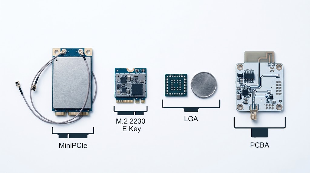
| MiniPCIe full card | 50.95 × 30.0 mm | PCIe 2.0 x1 / x2 | x1 / x2 | 52-pin edge | Industrial gateways, rugged designs |
| MiniPCIe half card | 26.8 × 30.0 mm | PCIe 2.0 x1 | x1 | 52-pin edge | Space-constrained embedded |
| M.2 2230 E Key | 22.0 × 30.0 mm | PCIe 3.0 / USB 2.0 | x1 / x2 | E Key, 75-pin | Thin AP, consumer routers, laptops |
| M.2 2280 B+M Key | 22.0 × 80.0 mm | PCIe 3.0 / SATA | x2 / x4 | B+M Key, 75-pin | Multi-function wireless + storage |
| PCBA (custom) | Custom | PCIe / SDIO / USB | As required | Custom BGA/LGA | OEM/ODM deep-embedded, thermal-critical |
| Feature | Mini-PCIe | M.2 (Key A/E) |
|---|---|---|
| Footprint | 30 × 50.95 mm | 22 mm wide; 30 / 42 / 60 / 80 mm long |
| Edge connector | 52-pin push-through | Key A/E (typically 75 pins) |
| Host interface | PCIe Gen1/2 x1 (2.5–5 GT/s), USB 2.0 | PCIe Gen2/3 x1–x2 (up to 8 GT/s), USB 2.0/3.0 |
| Supply | 3.3 V (aux rail for wake) | 3.3 V |
| Mounting | Screw retained | Snap / card-catch retained |
MiniPCIe vs M.2 for industrial
MiniPCIe offers superior mechanical retention via screw-mounting at both card edges, making it the choice for high-vibration environments such as in-vehicle gateways and robotic controllers. M.2 relies on a single screw at the mounting notch, which is less reliable than MiniPCIe’s two-edge retention under sustained random vibration — but its smaller footprint and lower profile (1.5 mm vs 2.5 mm component height) suit compact APs and SBCs. For new industrial designs in 2026, M.2 2230 E Key is increasingly preferred for chipset availability, while MiniPCIe stays in use for legacy upgrades and high-power designs that need extra PCB copper for thermal dissipation.
How the antenna reaches the outside world
Modules expose UF.L / IPEX MHF for internal trace antennas or pigtails, or RP-SMA for external antennas. Port count must equal spatial-stream count, and the keep-out area around each port directly affects RF performance.
- On-board PCB antenna — roughly $0.01–0.05 BOM at volume, no extra parts, but heavily dependent on enclosure material. Metal enclosures detune or block it entirely.
- IPEX/U.FL plus external antenna — best RF performance, adds roughly $0.10–0.30 at volume plus manual assembly.
- Ceramic chip antenna — the middle ground, pick-and-place compatible, but strict ground-plane clearance and keep-out rules apply.
Will the host interface and wired uplink keep up?
| Interface | Practical throughput | Best for |
|---|---|---|
| UART | ~1–3 Mbps (921,600 bps to 3 Mbps baud) | Low-power MCU sensors, AT-command control |
| SPI (high-speed, 40–80 MHz) | 20–50 Mbps | RTOS designs with deterministic timing, no SDIO/USB host |
| SDIO 2.0 / 3.0 | 50 Mbps / 208 Mbps (SDR104) | Linux and RTOS gateways, application processors |
| USB 2.0 / 3.0 | 480 Mbps / 5 Gbps | Prototyping, MCU hosts, multi-stream WiFi 6/7 |
| PCIe Gen2/3 x1–x2 | Multi-gigabit | WiFi 6/6E/7 peak performance, M.2 cards |
- PCIe lane. A 2.5 GT/s Gen1 x1 lane is roughly a 2.5 Gbps pipe — enough for late WiFi 5, marginal for multi-gig WiFi 7. Gen3 x2 unblocks modern multi-gig modules. Verify lane count and generation on the carrier before assuming the module runs flat out.
- CPU / DMA path. Sustained throughput also depends on host DMA engines, interrupt coalescing and memory bandwidth. A fast radio on a starved host still copies packet descriptors one at a time.
- Wired uplink. A WiFi 7 radio behind a single gigabit port cannot feed its multi-gig wireless link. Match the Ethernet PHY and any aggregation to real aggregate traffic.
Driver availability matters as much as electrical support. A module may support SDIO 3.0 electrically, but if your kernel version lacks a stable driver for that chipset, integration effort climbs sharply. Open-source in-kernel support — Realtek rtw88/rtw89, Qualcomm ath10k/ath11k, MediaTek mt76 — is a strong indicator of lower risk.
Is 6 GHz actually available in your market?
| Market | 6 GHz (unlicensed, general) | Practical effect |
|---|---|---|
| United States | 5925–7125 MHz (tiered, AFC for standard power) | WiFi 6E / 7 can use full 6 GHz: 7× 160 MHz or 14× 80 MHz channels |
| EU (CEPT) | 5945–6425 MHz (low part) | Reduced 6 GHz span vs US |
| Mainland China | Not opened for Wi-Fi 6E (general use) | 6E/7 radio falls back to 5 GHz |
There is also the 2.4 GHz reality: because it is narrow and congested, its practical maximum is 40 MHz channels (two non-overlapping at 40 MHz, three at 20 MHz), and even high-end radios top out around 229–300 Mbps there.
Always confirm the target region’s band plan and any power limits before committing — a dual-band 2.4/5 GHz module is sometimes the honest answer for a market where 6 GHz is off the table.
2×2 or 4×4 — what MIMO order do you need?
| Configuration | PHY rate | Real-world TCP | Power | Form factor |
|---|---|---|---|---|
| 2×2:2 (QCA9892) | 867 Mbps (80 MHz) | 400–500 Mbps | 2.0–2.5 W | M.2 2230 E Key, half-size MiniPCIe |
| 3×3:3 (QCA9880) | 1.3 Gbps | 500–650 Mbps | 3.0–4.0 W | Full-size MiniPCIe or M.2 3042 |
| 4×4:4 (QCN9074) | 4.8 Gbps (160 MHz) | — | 4.5–7.0 W | Full-size MiniPCIe / M.2 |
A 4×4 radio demands four radiators with enough spatial separation for the streams to be distinguishable — target above 20 dB isolation between co-located antennas — and a layout in which the added chains do not couple and re-radiate their own noise. Beamforming concentrates transmit energy toward the client and recovers useful link margin in sparse or noisy environments, but it is not a substitute for the raw power a long-range link needs.
Receive sensitivity is equally decisive: a module at −97 dBm (MCS0) has roughly 5–6 dB more link budget than one at −91 dBm, which is about 40–50% more range under identical conditions. Prioritise sensitivity for devices that must hold connections at range or through obstacles.
Which chipset is inside? (Qualcomm portfolio)
| Chipset | WiFi gen | MIMO | Max BW / band | PHY peak | Bands | Target market |
|---|---|---|---|---|---|---|
| QCN6024 | WiFi 6 | 2×2:2 | 80 MHz | 1.2 Gbps | 2.4 / 5 | Cost-sensitive IIoT, entry AP |
| QCN9024 | WiFi 6E | 2×2:2 | 160 MHz | 2.4 Gbps | 2.4 / 5 / 6 | Mid-range enterprise AP |
| QCN9074 | WiFi 6E | 4×4:4 | 160 MHz | 4.8 Gbps | 2.4 / 5 / 6 | Enterprise AP, industrial gateway |
| QCN6274 | WiFi 7 | 4×4:4 | 320 MHz | ~11.5 Gbps | 2.4 / 5 / 6 | Enterprise AP (volume 2026) |
| QCN9274 | WiFi 7 | 5×5:5 / 6×6:6 | 320 MHz | ~15+ Gbps | 2.4 / 5 / 6 | Carrier-grade, large enterprise |
| QCA2062 | WiFi 6E | 2×2:2 | 160 MHz | 2.4 Gbps | 2.4 / 5 / 6 | Industrial embedded, rugged tablets |
| QCA2066 | WiFi 6E | 2×2:2 | 160 MHz | 2.4 Gbps | 2.4 / 5 / 6 | Battery-powered mobile devices |
QCN6024 vs QCN9024
The QCN6024 is a 2×2:2 WiFi 6 part on 2.4 and 5 GHz with 80 MHz channels and 1024-QAM, delivering 1.2 Gbps — right for cost-sensitive IIoT gateways and entry-level APs. The QCN9024 spans all three bands with 2×2:2 per band and 160 MHz on 5 and 6 GHz for up to 2.4 Gbps per band, and handles 6 GHz LPI and SP modes under FCC rules with automated DFS and AFC compliance. That extra capability is not free in engineering terms: the 6 GHz RF front-end, the additional band-pass filtering needed to keep 5 and 6 GHz from interfering, and AFC compliance all add board area, design effort and qualification work. Whether that is worth carrying depends entirely on whether 6 GHz is actually usable in your target markets — see band plan.
QCN9074 — the enterprise and industrial workhorse
A 4×4:4 WiFi 6E solution supporting 160 MHz across all three bands with 1024-QAM for 4.8 Gbps per band. It supports up to 2,000 concurrent client associations per radio, DL and UL MU-MIMO, OFDMA, and distributed MU-MIMO for mesh backhaul. Industrial-grade modules built around it operate from −40 °C to +85 °C at +18 to +20 dBm per chain under 6 GHz LPI limits.
QCN6274 / QCN9274 — WiFi 7
The QCN6274 offers 4×4:4 per band with 320 MHz in 6 GHz, 4096-QAM and MLO across up to three bands. The QCN9274 steps to 5×5:5 or 6×6:6 for carrier-grade and large enterprise. Both implement 16-stream MU-MIMO, coordinated spatial reuse and preamble puncturing. As of 2026, QCN6274 modules are entering volume production in select enterprise AP designs while QCN9274 remains in pre-production sampling — plan 16–24 week lead times for module sampling and certification validation.
QCA2062 / QCA2066 — client-optimised tri-band
Both are 2×2:2 tri-band WiFi 6E parts with Bluetooth 5.3/5.4 coexistence, typically in M.2 2230 E Key. QCA2062 targets industrial embedded applications with −20 °C to +85 °C support and mature Linux/Android drivers; QCA2066 adds TWT and LDPC for battery-operated devices.
Does it need to survive −40 °C? (Industrial and IIoT)
| Parameter | Industrial-grade | Commercial-grade |
|---|---|---|
| Operating temperature | −40 °C to +85 °C (IEC 60068-2-1/2-2) | 0 °C to +70 °C |
| Component grade | I-grade ICs | C-grade ICs |
| PCBA material | High-Tg FR-4 (≥170 °C), ENIG, IPC-6012 Class 3 | Standard FR-4 (Tg ~130–140 °C), HASL, Class 2 |
| ESD (IEC 61000-4-2) | ≥ ±8 kV contact / ≥ ±15 kV air | ±2 kV contact / ±4 kV air |
| MTBF (predicted per Telcordia SR-332) | ≥ 300,000 h at 85 °C (~34 yr) | 50,000–100,000 h at 70 °C |
| Conformal coating | Standard option (acrylic / silicone / parylene) | Not typically available |
| Lifespan in continuous operation | 7–10+ years | 2–3 years |
| Relative unit cost | 2.5× – 4× | 1× baseline |
MTBF values are predictions calculated with the Telcordia SR-332 method from component count, quality level and temperature stress — they are not measured field life, and two vendors feeding different assumptions into the same method will publish different numbers. Use them to compare two quotes, not as a reliability guarantee.
Published figures for mean time between field failures vary widely, because the outcome depends far more on thermal design, duty cycle and enclosure than on the component grade label alone. Treat the 7–10 year versus 2–3 year figures above as design targets to validate against your own deployment conditions, not as guarantees — a commercial-grade module in a cool, lightly loaded enclosure will outlast an industrial-grade one cooked at its rated maximum.
Temperature is a design requirement
The −40 °C to +85 °C mandate cascades through every component: industrial-grade (I-grade) silicon, a TCXO with ±2 ppm stability versus the ±10–25 ppm typical of consumer XOs, laminate with Tg ≥ 170 °C to prevent warpage and pad lift, and solder joints verified by 500–1,000 thermal cycles per JEDEC JESD22-A104. A well-designed industrial module holds TX power within ±1 dB of its 25 °C value across the full range; anything requiring back-off above +70 °C or below −20 °C is not industrial-grade.
Environmental hardening
- EMC — IEC 61000-4-3 (radiated RF immunity, 80 MHz–6 GHz, 10 V/m per IEC 61000-6-2), -4-6 (conducted, 150 kHz–80 MHz, 10 V), -4-4 (EFT, ±2 kV on power ports). The shield can should provide at least 30 dB of shielding effectiveness from 100 MHz to 6 GHz.
- Vibration and shock — IEC 60068-2-6 (10–500 Hz, 2 g general / 5 g transport), -2-64 random, -2-27 (30 g / 11 ms general, 50 g transport). Require test reports showing no frequency drift beyond ±5 ppm.
- Humidity — IEC 60068-2-78 (40 °C, 93% RH, 56 days) and -2-30 cyclic. Uncoated modules in humid outdoor deployments fail markedly earlier than conformal-coated ones, and the gap widens as soon as condensation inside the enclosure becomes possible. Coating is cheap insurance — acrylic AR-grade typically adds roughly $0.30–0.80 per module at volume — and is standard practice for outdoor and high-humidity installations.
Security
WPA3-SAE has been mandatory for new Wi-Fi CERTIFIED devices since July 2020 and replaces the WPA2-PSK handshake susceptible to offline dictionary attacks. Industrial terminals on corporate or utility networks need 802.1X with EAP-TLS, IEEE 802.11w protected management frames to block de-authentication attacks, and hardware-accelerated AES-CCMP/GCMP rather than software encryption, which adds latency and burns host CPU cycles.
Driver maturity decides schedule, not silicon
Prefer chipsets with mainline Linux drivers — Qualcomm ath9k/ath10k/ath11k, MediaTek mt76, Intel iwlwifi, Realtek rtw88/rtw89 — over out-of-tree drivers that need re-patching on every kernel upgrade. A well-documented SDK with reference examples can cut integration from 8–12 weeks to 2–4 weeks. For full IIoT scenario walkthroughs, see our dedicated industrial control IoT terminal module guide.
WiFi 5 vs 6 vs 6E: the decision matrix
| Decision factor | WiFi 5 (802.11ac) | WiFi 6 (802.11ax) | WiFi 6E |
|---|---|---|---|
| Link distance | > 5 km typical for engineered PtP links | < 3 km | < 1 km (LPI limited, higher path loss) |
| Device density | < 32 devices/AP (CSMA/CA) | 128+ devices/AP (OFDMA) | 500+ devices/AP |
| Peak throughput | 867 Mbps PHY, 350–500 Mbps TCP | 1.2 Gbps PHY, 500–800 Mbps TCP | 1.2 Gbps PHY (2×2) |
| Industrial temp (−40 to +85 °C) | Widely available | Emerging | Not available as of 2026 |
| Module cost (indicative, 1k–10k volume) | $8–$15 | $18–$35 | $35–$60 |
| Certification coverage (modular) | Global (FCC/CE/TELEC/KC/BSMI) | Major markets | Limited |
| Host interface options | SDIO, USB, UART, SPI, PCIe | PCIe, SDIO (limited), USB | PCIe only (M.2 Key E) |
| Best suited for | Outdoor PtP bridges, RTUs, cost-sensitive terminals | Smart factories, warehouses, high-density IIoT | Edge AI, AR/VR, ultra-dense campuses |
The distance row rests on physics rather than benchmarks. 5 GHz 802.11ac point-to-point links with high-gain directional antennas and clear line of sight routinely reach tens of kilometres — long-range records above 300 km have been set, though those are engineered shots between mountain tops with dish antennas and say nothing about what a module achieves inside a product. What does transfer to your design is the direction of the difference: free-space path loss rises with frequency, so 6 GHz costs roughly 1.6 dB more than 5 GHz and about 8 dB more than 2.4 GHz at the same distance, before the LPI power limits are even applied. For outdoor links, WiFi 6E and 7 are the wrong choice regardless of their headline rate. For the density row, work from the concurrent-client thresholds above rather than the per-AP totals printed in brochures.
Module cost is indicative street pricing at 1k–10k volume. It moves with chipset generation, band count, certification coverage and market conditions — read it as a relative ordering between generations, not as a quote. Request current pricing for your volume and target markets.
Custom OEM/ODM or a pre-certified module?
| Selection dimension | OEM/ODM custom project | Brand-oriented selection |
|---|---|---|
| Primary driver | Design integration flexibility, BOM optimisation | Brand consistency, UX, supply reliability |
| Form factor | Custom LCC/LGA footprint, specific pin mapping | Standardised LCC/LGA/M.2, proven mechanical compatibility |
| Firmware | Fully customisable (vendor SDK based) | Vendor-provisioned stable release, limited customisation |
| RF tuning | TX power, sensitivity, band filter tailoring | Standard reference design compliance |
| Certification ownership | Module-level + end-product (shared) | Module pre-certified, brand handles end product |
| Volume commitment | Medium-to-high (10K–500K+) | High (100K+, multi-year) |
| Lead time to MP | 10–16 weeks including validation | 6–10 weeks (pre-qualified module) |
Typical custom module parameters
- Conducted TX power +16 dBm (standard) to +21 dBm (high-power custom)
- RX sensitivity −71 dBm or better at MCS7 HT20; −60 dBm or better at MCS11 HE160 for WiFi 6
- EVM better than −32 dB for 256-QAM and −35 dB for 1024-QAM
- Operating −40 °C to +85 °C for industrial, validated with at least 500 hours accelerated life testing
Five phases from RFQ to ramp
- Requirements definition (week 1) — protocol generation and minimum PHY rate, host interface and voltage domain, mechanical envelope, temperature range, target markets, annual volume and ramp timeline.
- Vendor shortlisting (weeks 2–3) — RFQ to 3–5 qualified vendors; evaluate custom design capability, certification portfolio, production track record and FAE model. Ask for datasheets from at least two similar delivered projects.
- Technical evaluation (weeks 4–6) — measure conducted TX power, EVM, RX sensitivity and current across sleep/active/TX; run a 72-hour stability test under expected environmental conditions.
- Design-in and validation (weeks 7–12) — integrate into the prototype PCB, radiated test in the target enclosure, thermal imaging for hot spots, pre-compliance EMC, and firmware integration.
- Certification and ramp (weeks 13–18) — full certification plus a 500–2,000 unit pilot batch to validate SMT yield, programming yield and functional test coverage.
Four risks that derail custom programmes
- Underestimating RF design sensitivity — changing footprint, antenna matching network or stack-up shifts performance significantly. Run a 50–100 unit pre-production RF batch measuring TX power, EVM and sensitivity at three temperature points against the reference baseline.
- Firmware integration delays — budget at least 4 weeks, and contractually fix the beta release, validation feedback window and final release milestones.
- End-product certification failure — even with a pre-certified module, enclosure design or component placement can fail radiated or spurious emission tests. Bring in a pre-compliance lab around weeks 6–8; a problem found there is far cheaper to fix than the same problem discovered during full certification, where it can mean a board re-spin.
- Custom component supply disruption — require a lead-time report for every custom BOM item and second-source critical passives before production begins.
Vendor qualification checklist: annual SMT capacity (tier-1 exceeds 50 million units), first-pass test yield above 97%, ppm defect rate under 500, ISO 9001:2015 (IATF 16949 or ISO 13485 for automotive/medical), preferred-partner status with the chipset vendor, and references from at least two comparable custom programmes.
What does certification actually require?
Two paths exist, and the gap between them is the largest single lever you have on both cost and schedule:
- Full end-product certification — you certify your own RF design. Every band, every antenna variant and every significant hardware revision needs its own approval, and a change to the RF section usually means re-testing.
- Modular certification — you adopt a module that already holds its own approval and inherit it, provided you do not modify the RF section and you meet the module vendor’s antenna and host conditions.
Which approvals you need depends on where you ship:
| Market | Approval | Body | Standards |
|---|---|---|---|
| USA | FCC | FCC | Part 15.247 (2.4 GHz), 15.407 (5 GHz), Part 15E (6 GHz) |
| EU | CE (RED) | EU Commission | EN 300 328 (2.4 GHz), EN 301 893 (5 GHz), EN 303 687 (6 GHz) |
| Japan | TELEC | MIC | Article 49-20 |
| Korea | KC | RRA | MSIP standards |
| Taiwan | BSMI | BSMI | CNS 13438, CNS 14336-1 |
| Canada | IC | ISED | RSS-247 |
| China | SRRC | SRRC | National radio type approval |
| EU / national | RoHS / REACH | EU / national | 2011/65/EU (RoHS 3), 1907/2006 |
Standard versions and national requirements change; confirm the current issue of each standard with your test house before booking lab slots. Links in References.
Enterprise equipment typically adds Wi-Fi Alliance certification for WPA3-Enterprise and 802.11 interoperability; industrial products may need IEC 60068 environmental testing and UL 62368-1 safety certification.
Six traps that survive every spec sheet
| Symptom in the field | Root cause | What to write into the spec instead |
|---|---|---|
| WiFi 6 was bought, but throughput and latency did not improve — BOM and active power both went up | Fewer than roughly 15 concurrent clients per radio, so there is no density for OFDMA to multiplex | Size the generation from concurrent active clients, not the brochure count — see density and airtime |
| A 6E radio never actually reaches 6 GHz; throughput equals a 5 GHz part | Either the target market has not opened 6 GHz, or the peer AP and clients do not support it — 6 GHz needs both ends | Confirm the market band plan and the peer’s 6 GHz support before specifying 6E/7 — see band plan |
| Lab throughput never reproduces in the field; performance collapses at the coverage edge | The design was pinned to the maximum MCS, which needs an SNR only part of the cell ever has | Specify the throughput required at the cell edge and the MCS that delivers it, not the peak MCS on the datasheet |
| A multi-gig radio delivers only about 940 Mbps | The wired uplink or the PCIe lane is the bottleneck, not the radio | Match the Ethernet PHY and the PCIe generation and lane count to the radio’s aggregate rate — see host interface |
| The module throttles or resets after a few minutes of heavy traffic | A 4×4 module dissipates about 6 W in continuous TX inside a sealed, passively cooled enclosure — and up to 16 W at the rated worst case; or the supply rail droops on TX current peaks in the hundreds of milliamps with microsecond-scale rise times | Set a case-temperature limit at worst-case TX, and a dedicated 3.3 V buck rated at least 3.5 A within 15 mm of the connector — see power and thermal |
| Field failures appear after 12–24 months in humid, coastal or outdoor sites | Commercial-grade module with no conformal coating: in humid or coastal outdoor sites, uncoated modules fail markedly earlier than coated ones once condensation becomes possible | Specify −40 °C to +85 °C, IEC 60068-2-78 humidity validation and conformal coating — see industrial and IIoT requirements |
References
- Wi-Fi Alliance — Wi-Fi CERTIFIED 6 / 6E / 7 certification specifications — wi-fi.org
- IEEE Std 802.11ac-2013, 802.11ax-2021, 802.11be (draft 3.0, March 2024) — standards.ieee.org
- Qualcomm Technologies — QCN9074 Product Brief; WiFi 7 Networking Pro Series (QCN9274 / QCN6274) — qualcomm.com
- MediaTek — Filogic 830 WiFi 6/6E platform — mediatek.com
- Realtek — RTL8852BE WiFi 6E + Bluetooth 5.3 combo controller — realtek.com
- FCC — 6 GHz Report and Order, ET Docket No. 18-295 — fcc.gov
- ETSI — EN 300 328, EN 301 893, EN 303 687 — etsi.org
- IEC — 60068-2 (environmental testing), 61000-4 (EMC), 61000-6-2 — iec.ch
- Telcordia SR-332 — reliability prediction for electronic equipment
- IPC — IPC-6012D (rigid printed boards), IPC-CC-830 (conformal coating)
- SparkLAN — WPEQ-405AX datasheet rev. 1.0 (2022), QCN9074 4×4 802.11ax Mini PCIe module, TX/RX current and per-chain conducted power — sparklan.com
- 8devices — Pineapple (QCN9074) module family: 16 W power consumption, 28/25/24 dBm max output power per chain at 2.4/5/6 GHz — 8devices.com
Frequently Asked Questions
Q: Which WiFi generation should I choose for a new design in 2026?
Choose WiFi 5 Wave 2 for sub-50-client IIoT, outdoor point-to-point links and tight BOM targets ($8–$15 per module). Choose WiFi 6 for 50–200 clients per radio needing OFDMA efficiency ($18–$35). Choose WiFi 6E where 6 GHz is open and the application is latency- or throughput-sensitive. Choose WiFi 7 only for above 10 Gbps aggregate or MLO sub-5 ms latency — it currently carries a 2–3× premium over WiFi 6E.
Q: What is the difference between WiFi 5 Wave 1 and Wave 2 modules?
Wave 1 supports 80 MHz, 3 spatial streams and a 1.3 Gbps theoretical peak. Wave 2 adds 160 MHz (contiguous or 80+80 MHz), 4 spatial streams and downlink MU-MIMO for 3.47 Gbps. Typical measured TCP throughput is 400–600 Mbps for Wave 1, versus 600–900 Mbps at 80 MHz and 800–1200 Mbps at 160 MHz for Wave 2 — and only where RF conditions and the client’s own stream count support it. Wave 2 MU-MIMO is commonly credited with roughly 2–2.5× aggregate throughput in multi-client environments and zero benefit for single-client or uplink-heavy use.
Q: Should I choose M.2 E Key or B+M Key for my WiFi module?
E Key, always, for pure WiFi. It routes PCIe 3.0 x1 at 8 GT/s, USB 2.0, UART, I2C and PCM — sufficient for WiFi 7 PHY rates. B+M Key adds SATA and USB 3.0 for WWAN or storage combo modules. E Key uses a single notch (pins 24–32), B+M Key has dual notches (pins 12–19 and 59–66). Never force an E Key module into a B Key slot even if the width fits.
Q: What is the real-world throughput difference between 2×2 and 3×3 MIMO?
A 2×2:2 module such as the QCA9892 reaches 867 Mbps PHY and roughly 400–500 Mbps TCP; a 3×3:3 module such as the QCA9880 reaches 1.3 Gbps PHY and 500–650 Mbps TCP under the same RF conditions. The 3×3 variant needs full-size MiniPCIe or M.2 3042 for the extra RF chain, while 2×2 fits M.2 2230 E Key and half-size MiniPCIe.
Q: Is 6 GHz available everywhere for WiFi 6E and 7?
No. The US opened 5925–7125 MHz (tiered, standard power under AFC); the EU uses a reduced 5945–6425 MHz span; mainland China has not opened 6 GHz for general Wi-Fi use, so a 6E/7 module there falls back to 2.4/5 GHz. Always confirm the target market’s band plan before committing.
Q: What temperature range do industrial-grade modules support?
Standard industrial modules cover −20 °C to +70 °C; extended-range variants using chipsets such as the Qualcomm QCA9892 or MediaTek MT7612E cover −40 °C to +85 °C, validated per IEC 60068-2-14 thermal cycling. Consumer modules typically cover only 0 °C to +60 °C. For outdoor deployment or equipment near machinery, always specify the extended industrial range.
Q: How much power does an industrial WiFi module draw?
By stream count in active TX: 2×2:2 about 2.0–2.5 W, 3×3:3 about 3.0–4.0 W, 4×4:4 about 4.5–7.0 W, dropping to 10–50 mW in doze. A QCN9074 4×4 module measures roughly 1954 mA at 3.3 V in continuous TX (about 6.4 W) and 819 mA in RX (about 2.7 W). Budget for worst-case TX, not average.
Q: What certifications are needed for WiFi modules in industrial and enterprise products?
US: FCC Part 15.247/15.407, with modular approval available. EU: CE under RED 2014/53/EU — EN 300 328 for 2.4 GHz, EN 301 893 for 5 GHz, EN 303 687 for 6 GHz. Canada: IC RSS-247. China: SRRC. Enterprise equipment typically adds Wi-Fi Alliance certification; industrial products may need IEC 60068 environmental testing and UL 62368-1 safety certification.
Q: What is Multi-Link Operation (MLO) and why does it matter?
MLO is a WiFi 7 feature that lets a module transmit and receive simultaneously across the 2.4, 5 and 6 GHz bands. Unlike WiFi 6/6E, where a device uses one band at a time, MLO aggregates bandwidth across bands and provides redundancy for sub-5 ms latency — critical for industrial control. Both the module and the access point must support WiFi 7.
Q: How long does a custom OEM/ODM WiFi module take to develop?
10–16 weeks from spec freeze to mass-production-ready: schematic and PCB layout 2–3 weeks, prototype fabrication and assembly 2–3 weeks, RF tuning and firmware bring-up 3–4 weeks, design validation testing 2–3 weeks, and certification 4–8 weeks running in parallel where possible. Custom LGA footprint design or major firmware changes push it toward 16 weeks.