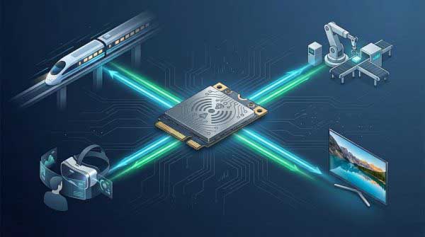
Chipset Profile · Wi-Fi 6E (802.11ax)
QCN9074 Deep Dive: The 4×4 Wi-Fi 6E RFIC Behind Dense Enterprise APs
TL;DR. The Qualcomm QCN9074 is an 802.11ax Wi-Fi 6E radio (RFIC), not a finished product. Its headline figure — 4804 Mbps aggregate PHY — is reached only at 4×4 MIMO, a 160 MHz channel and the densest 1024-QAM modulation, all under favourable signal conditions. What actually makes it an enterprise-chip is the multi-user machinery behind the number: simultaneous downlink and uplink MU-MIMO (up to four users per PPDU), downlink and uplink MU-OFDMA (up to 37 users per PPDU), four spatial streams on 2.4/5/6 GHz, and a dual-lane PCIe´ Gen 3 host interface. Read it as a capacity engine for the 80th client, not a single-client speed race, and budget the power, the 6 GHz regulation and the wired uplink accordingly.
A “4.8 Gbps” figure on a spec sheet invites the wrong mental model. People read it as “one connection gets very fast.” The QCN9074 is engineered for the opposite question: how does the eightieth simultaneous client experience the network, and how predictable is that experience minute to minute? This guide dissects what the datasheet actually says, derives the headline rate from first principles, and lays out the power, thermal, interface and regulatory conditions under which the part earns its place in a real enterprise access point.
Contents
- What the QCN9074 actually is
- Anatomy of the 4.8 Gbps headline
- The multi-user story: MU-MIMO and MU-OFDMA
- Datasheet parameter table
- Power, the interface, and the wired uplink
- Thermal and reliability law
- The 6 GHz band and what it really buys
- Where it fits — and where it does not
- Where it sits in the Pine family
- Deployment checklist
- Glossary
What the QCN9074 actually is
The QCN9074 is a highly integrated wireless LAN system-on-chip manufactured by Qualcomm Technologies. Per the official data sheet, it is built for enterprise access points and campus deployments using IEEE 802.11ax (Wi-Fi 6) / 802.11ac / 802.11n / 802.11a/b/g. It performs both access-point and station (client) functionality with 4×4 MIMO and four spatial streams, and it is a dual-synthesizer radio with native 160 MHz support in the 2.4, 5 and 6 GHz bands.
The critical technical distinction is that the 9074 is a radio you integrate, not a module you bolt on. The block diagram shows the Wi-Fi MAC/PHY, four TX and four RX baseband chains, an all-CMOS transceiver, and a portion of the PCIe interface — but the actual power amplifiers (PAs) and low-noise amplifiers (LNAs) that define the transmit power and receive sensitivity live off-chip, driven through explicit external interfaces: four interfaces to external 2.4 GHz PAs, and four interfaces to external PAs covering 4.9–7.125 GHz. This is why identical QCN9074 boards from different vendors can genuinely differ in output power, sensitivity and overall link budget — the reference design is only half the story; the front-end module (FEM) and antenna are the other half.
Because the silicon does so much in the MAC/PHY, it also embeds a CPU with local SRAM for time-critical management of the medium-access layer. Its feature list is substantial even before the multi-user additions: explicit transmit beamforming (TxBF) in both 11ax and 11ac, dynamic bandwidth switching, agile DFS with channel-3 scanning, maximum-likelihood (ML) decoding, low-density parity-check (LDPC) coding, maximum-ratio combining (MRC) and space-time block coding (STBC). Those matter because they translate raw RF into usable link margin and reliability in a crowded office.
Anatomy of the 4.8 Gbps headline
The QCN9074 data sheet states a maximum PHY rate of 4804 Mbps in 802.11ax 4×4/160 MHz native operation on the 5 or 6 GHz band. That number is arithmetic, not marketing, and understanding the arithmetic is the single best antidote to mistaking peak for real.
A 160 MHz 802.11ax channel carries approximately 1960 data subcarriers. At 1024-QAM each symbol carries 10 bits, and a 5/6 forward-error-correction code is applied. Dividing carried bits by the OFDM symbol time at a 0.8 µs guard interval (13.6 µs per symbol) gives about 1.2 Gbps for a single spatial stream; multiply by four streams to reach roughly 4.8 Gbps aggregate.
802.11ax 160MHz: 1960 subcarriers x 10 bits (1024-QAM) x 5/6
/ 13.6 us ~ 1.2 Gbps (1-SS)
x 4 spatial streams ~ 4.8 Gbps (4-SS aggregate)
Three qualifications are essential before that number means anything. First, the 4.8 Gbps is the physical-layer ceiling; MAC overhead, airtime arbitration, retransmissions and the receiver’s achievable modulation typically cut delivered throughput to a fraction of it. Second, the densest modulation (1024-QAM, MCS 11) requires a high signal-to-noise ratio that only exists close to the AP and with a clean channel — it is a leaflet of the radio’s capability, not a coverage plan. Third, an aggregate PHY of 4.8 Gbps cannot be fed by a single gigabit wired port or a single PCIe Gen 1 lane; the downstream and upstream paths must both be sized for it (covered under interface below).
On the 2.4 GHz band the numbers are far smaller and that is intentional: the QCN9074 tops out around 573.5 Mbps at 20 MHz and 1147 Mbps at 40 MHz on 2.4 GHz, because 802.11ax caps modulation and channel width there and the band itself is narrow and congested. Anyone advertising “5 Gbps Wi-Fi” from a QCN9074 is citing the 5/6 GHz 4×4 aggregate, and only under ideal conditions.
The multi-user story: MU-MIMO and MU-OFDMA
The real reason a dense-room AP picks a QCN9074 is not single-client peak but how many active clients it can service in the same frame time. Two complementary mechanisms do that work, and the datasheet itemises both.
MU-MIMO. The QCN9074 supports simultaneous downlink and uplink multi-user MIMO, up to four users per PPDU (packet). MU-MIMO sends independent spatial streams to (or from) several clients at once, using the antenna field’s spatial degrees of freedom. It pays off only when clients have the antennas and spatial separation to be addressed independently, which is why a high-density floor with mixed 2×2 and 3×3 clients benefits more than a handful of 1×1 sensors do.
MU-OFDMA. The datasheet lists downlink and uplink multi-user OFDMA up to 37 users per PPDU. OFDMA divides a single channel into smaller resource units (RUs) and lets many clients transmit in the same instant — the mechanism that prevents one slow or legacy frame from stalling the whole channel. Up to 37 simultaneous users in a transmission is a genuinely dense-airtime capability.
MU-MIMO ………… DL + UL, up to 4 users / PPDU
MU-OFDMA ……….. DL + UL, up to 37 users / PPDU
spatial streams …. 4 (4×4 MIMO)
The practical meaning for an enterprise radio: a QCN9074 AP does not idle its medium waiting for a slow preamble. It packs small packets from many clients into one OFDMA frame and serves multiple high-capacity clients on parallel streams. That is precisely what a 40–80 active-client office, lecture hall or venue floor needs — and it is why the vendor claims “let many clients transmit at the same instant” matter more than the raw bit rate.
Datasheet parameter table
The table below compiles the parameters that matter at design time, drawn from the Qualcomm QCN9074 data sheet and representative vendor modules (Wallys DR9074E, Nanjing MaXon MX6974, Compex WLE3000HX family).
| Parameter | Reference value | Notes |
|---|---|---|
| Bands | 2.4 / 5 / 6 GHz | Tri-band, one radio; 6 GHz full-band 5.925–7.125 GHz |
| MIMO / streams | 4×4, 4 spatial streams | AP and STA modes |
| Peak PHY (5/6 GHz) | 4804 Mbps | 4×4 / 160 MHz, 1024-QAM |
| Peak PHY (2.4 GHz) | 573.5 / 1147 Mbps | 20 / 40 MHz caps |
| Channel widths | 20/40/80/160 MHz | 160 MHz native on 5 and 6 GHz |
| MU-MIMO | DL + UL, up to 4 users | Per PPDU |
| MU-OFDMA | DL + UL, up to 37 users | Per PPDU |
| Host interface | PCIe Gen 3, 1 or 2 lanes | Dual-synth, native 160 MHz |
| External PA paths | 4 (2.4 G) + 4 (4.9–7.125 G) | Front-end-module dependent TX power |
| Package | 11.1 × 12 mm FCBGA, 0.65 mm pitch | Chip-level; modules add FEM + board |
| TX power (module, per chain) | ~20–21 dBm | Vendor-dependent; e.g. MaXon MX6974 lists 21 dBm @ HE |
| Operating temp | −20 to +70 °C (typ) | Commercial modules; some industrial variants −40 to +85 |
Two rows deserve extra weight. The PCIe Gen 3 interface at one or two lanes is the difference between a radio that can be fed and one that cannot: two Gen 3 lanes provide roughly 16 Gbit/s of transport, comfortably above the 4.8 Gbps aggregate. And the external-PA architecture explains why TX power is not a silicon constant — it is set by the FEM the board designer attaches.
Power, the interface, and the wired uplink
A 4×4, multi-user radio is an energy consumer, and every amp flows through design decisions. Module-level figures in the QCN9074 ecosystem give a grounded picture: a commercial-grade 4×4 Wi-Fi 6 module is commonly specified with a case-maximum power around 9 W, and higher-power 6E variants a little above that. Per-chain transmit power is on the order of 20–21 dBm at the highest MCS for common modules, which is enough for most indoor enterprise coverage but far short of the +26 to +30 dBm per chain that long-range outdoor bridges chase.
module case-max ………… ~9 W (typ), higher on high-power FEM
per-chain TX (highest MCS) . ~20-21 dBm
host interface ………… PCIe Gen3, 1-2 lanes (11ax aggregate unusable on 1 GbE uplink)
The wiring consequence is often the least-expected. A 2.4 Gbps or 4.8 Gbps aggregate PHY is meaningless behind a single 1 Gbps Ethernet uplink or a Gen 1 PCIe slot. Two of the most common real-world failures with high-end Wi-Fi 6E cards are not slow radios — they are radios throttled by a gigabit uplink and by a host CPU/NIC that cannot sustain the descriptor and interrupt rate. Design the wired backhaul and the PCIe lane count to the aggregate traffic you expect, not the single-client peak.
Interrupt coalescing, DMA capability and memory bandwidth on the host also decide sustained throughput. A QCN9074 behind a starved host still delivers data — one packet descriptor at a time. The radio is the easy part; the platform around it determines whether the headline survives contact with the network.
Thermal and reliability law
Power draw and heat are inseparable, and both constrict the enclosure. At several watts in sustained multi-user service, a sealed, passively cooled plastic AP has to move that heat out somewhere. Commercial modules in the QCN9074 ecosystem are typically rated −20 °C to +70 °C operating, with storage −40 to +90 °C, and non-condensing humidity roughly 5–95%. Variants labelled industrial grade extend the operating window to about −40 to +85 °C — a real difference for outdoor, pole- and ceiling-adjacent deployments that see the sun.
Reliability also favours mature silicon. The QCN9074 is in active production across enterprise and industrial vendors, giving a track record of field hardening, calibration and driver maturity that matters when a product must ship and be serviced for years. The open-source driver path through ath11k (mainlined in recent kernels for 11ax) is a practical advantage for Linux-based APs, versus a closed firmware approach that constrains customisation.
The 6 GHz band and what it really buys
The 6 GHz lane is a large part of why a QCN9074 is chosen over a dual-band-only part. In regulatory domains that have opened it, Wi-Fi 6E operates over up to 1200 MHz of newly available spectrum (5.925–7.125 GHz in the United States). That cleans up the air in three concrete ways: no legacy 802.11 a/b/g/n/ac devices exist there, so co-channel interference from old radios disappears; there is room for seven 160 MHz or fourteen 80 MHz non-overlapping channels; and most of the band is largely free of the radar-signal DFS evacuations that interrupt 5 GHz channels.
Qualcomm’s own Wi-Fi 6E material emphasises these exact benefits: more spectrum, less interference, and significantly reduced latency because the clean 6 GHz lane is occupied only by efficient Wi-Fi-6-class traffic. Independent field studies have reported meaningfully lower average latency and less jitter on 6 GHz versus a contended 5 GHz band — which matters for VR, VoIP, industrial control and other latency-sensitive workloads.
Where it fits — and where it does not
The QCN9074 is purpose-built for a specific slice of the market: medium-to-high density enterprise service. The honest fit profile is narrower than many spec-sheet-driven buyers assume.
| Deployment | Fit | Reasoning |
|---|---|---|
| Open-plan office, ~40–80 active clients / AP | Excellent | MU-MIMO + MU-OFDMA + 6 GHz offload shine here |
| Lecture hall / venue, 80+ clients | Strong | High aggregate capacity; pair with multi-gig uplink |
| Small office / home, <15 clients | Overkill | No density to multiplex; cheaper part delivers same single-client experience |
| Ultra-low-power battery IoT | Wrong tool | WLAN SoC with TWT and lower active draw wins |
| Long-range outdoor bridge (>10 km) | Marginal | Needs high per-chain TX power + outdoor FEM; not the 9074’s core strength |
The unifying rule: choose the QCN9074 when you need to serve many concurrent, active clients at once, with predictable low latency — and when you can feed it (multi-gig uplink), power it (several watts), cool it and legally operate 6 GHz. When the job is a single fast client in a quiet room, it is the wrong investment.
Where it sits in the Pine family
The QCN9074 is one rung of a ladder. Knowing the family prevents both overspending and undersizing. Within the 11ax access-point generation, Qualcomm positions the parts as follows in the Pine/NPro family (with vendor module implementations):
| Part | Bands | Streams | Typical role |
|---|---|---|---|
| QCN6024 | 2.4 + 5 GHz | 2×2 (some 4×4) | Dual-band Wi-Fi 6 workhorse, cost-sensitive boards |
| QCN9024 | 2.4 + 5 + 6 GHz | 2×2 / 4×4 | Tri-band Wi-Fi 6E; adds the 6 GHz lane |
| QCN9074 | 2.4 + 5 + 6 GHz | 4×4 | High-density tri-band Wi-Fi 6E AP radio (this guide) |
The 6024 is the entry point when 6 GHz is unnecessary; the 9024 adds the 6 GHz band; the 9074 adds full 4×4 capacity on top. Several commercial modules (notably Compex’s WLE3000HX) ship the same board in commercial (QCN6024/9024) and industrial (QCN9074) grades, illustrating how one form factor spans the family. For the wider upgrade path into 11be, the 2024-2025 Wi-Fi 7 generation (e.g. QCN9274/QCN6274) carries the multi-link features beyond this profile — see the 802.11be deep dive.
Reading the MCS table, not just the peak
A datasheet’s single peak number hides a ladder. The 802.11ax modulation-and-coding scheme (MCS) tables step from robust low-rate modes to the fragile densest one, and the honest way to evaluate a QCN9074 is to ask what rate the average client holds, not what the best client can hit on the best day.
| MCS | Modulation | Code rate | ~Rate (1-SS, 160 MHz) | Typical use case |
|---|---|---|---|---|
| 0 | BPSK | 1/2 | ~150 Mbps | Edge of coverage, robust |
| 3 | 16-QAM | 3/4 | ~450 Mbps | Mid-range, moderate SNR |
| 7 | 64-QAM | 5/6 | ~750 Mbps | Indoor mid-field |
| 9 | 256-QAM | 3/4 | ~980 Mbps | Near-field, good SNR |
| 11 | 1024-QAM | 5/6 | ~1.2 Gbps | Very close, clear channel (peak) |
The practical lesson is that density features and receiver quality determine where clients sit on this ladder. A QCN9074 at MCS 11 in a lab and a QCN9074 at MCS 3 across a noisy open floor are the same silicon producing very different experiences. When you compare module cards, ask for the rate-and-reach curve per MCS against real client antennas rather than a one-line peak. That is where receiver sensitivity, MRC and beamforming earn their cost — by holding a client on a higher MCS farther out and through multipath.
How MU-OFDMA actually schedules a room
It helps to visualise the airtime machinery that makes “37 users in one PPDU” possible, because it explains both the strength and the limit of the QCN9074 in dense rooms. Legacy OFDM served one client per transmission opportunity; if nine clients each had a three-millisecond packet, they queued. MU-OFDMA instead splits the channel width into resource units — smaller sub-channels allocated in the frequency domain — and the AP schedules several clients’ data into the frequency-time grid of a single frame.
That re-scheduling is why latency collapses under load: instead of waiting for the whole channel to free, a Wi-Fi 6 AP packs small telemetry, voice or web packets from many clients into one short frame. The uplink version (triggered UL MU-OFDMA) extends the same idea to the return path, with the AP polling many clients in one trigger frame instead of each client individually bidding for the medium. For a room of interactive users, this is the difference between a network that thrashes and one that stays flat under peak load.
A worked density calculation
To make “capacity not speed” concrete, run a simple arithmetic sanity check for a representative room before choosing the radio.
target ………… 60 active clients @ 1 Mbps sustained each
application want … ~60 + 25% headroom ~ 80 Mbps delivered
80 MHz PHY at 3-SS average MCS 7-9 …….. ~700-900 Mbps PHY
typical delivered efficiency (MAC + retry) ~ 40-55% of PHY
delivered ceiling ….. ~300-500 Mbps >> 80 Mbps needed
verdict ……….. one 4×4 cell has ample airtime margin for this profile
The nuance the arithmetic exposes: a single 4×4 cell is rarely the bottleneck for ordinary office density — the wired uplink, the client mix, or co-channel interference from neighbouring APs usually binds first. The QCN9074’s 4×4 and 6 GHz offload buy you margin: room to absorb density spikes, wider channels free of DFS, and a clean band for latency-sensitive traffic. If your requirement is a quiet room with one fast client, the arithmetic above is the reason the part is overkill.
6 GHz regulation, market by market
Because the 6 GHz lane is central to the QCN9074’s value but not uniform worldwide — a global product must treat the band as a graduated set of approvals, not a single fact. The patterns that actually decide your board:
- United States (FCC): 5.925–7.125 GHz opened unlicensed, tiered into standard-power and low-power indoor classes; standard power operates under an automated frequency coordination (AFC) regime. Roughly 1200 MHz of headroom — the fullest Wi-Fi 6E case.
- European Union (CEPT/ECC): a narrower 5945–6425 MHz lower segment is generally available for low-power indoor; the upper part of the US band is not open in the same way. Less span than the US.
- Other regions: availability ranges from full 6 GHz to a partial slice to none at all; mainland China, for example, has not generally enabled Wi-Fi 6E in the 6 GHz band, so a tri-band part shipped there falls back to 5 GHz.
This is the same regulatory floor the QCN6024 vs QCN9024 and 6 GHz bridge guides discuss in the context of part selection, and it reinforces the theme: the radio’s band claim only matters where the law opens the band.
Deployment checklist
- Match the uplink to the aggregate. Use at least a 2.5 G (ideally 5–10 G) wired port and enough PCIe lanes for the AP, or the radio’s capacity is unreachable.
- Verify 6 GHz regulation first. Standard power may need AFC; confirm the approval picture for every target market before committing (see the QCN6024 vs QCN9024 guide).
- Budget the heat. Size the enclosure and any heatsink for sustained service, not idle current; industrial-grade variants widen the operating window for hot outdoor installs.
- Design for four antennas. 4×4 MIMO needs four well-isolated radiators; an unbalanced array gives away the radio’s promise quietly.
- Plan the driver path. For Linux, confirm the
ath11ksupport for your kernel; for proprietary SDKS, lock the firmware and BSP with the vendor. - Decide the FEM. TX power and sensitivity come from the external PA/LNA chain — choose the module whose FEM matches your coverage ambition, then verify its per-chain table against the MCS you expect.
Frequently asked questions
What is the Qualcomm QCN9074?
The QCN9074 is a highly integrated Wi-Fi 6 / 6E wireless LAN system-on-chip for enterprise access points. It is a dual-synthesizer 4×4 MIMO radio with four spatial streams and native 160 MHz support on 2.4, 5 and 6 GHz, and it performs both access-point and station roles. It is a radio you integrate — the power amplifiers and LNAs live off-chip, so real TX power depends on the front-end module a board designer attaches.
Is the QCN9074’s 4.8 Gbps speed real?
The 4804 Mbps figure is real arithmetic — about 1.2 Gbps per spatial stream (1960 subcarriers at 1024-QAM, 5/6 code rate, 0.8 µs guard interval) times four streams. But it is the physical-layer ceiling on 160 MHz in 5/6 GHz; real TCP throughput is a fraction of it, requires nearby clients with clean channels, and needs a multi-gig uplink and PCIe Gen 3 lanes to actually feed it.
Is the QCN9074 a Wi-Fi 7 chip?
No. The QCN9074 is an 802.11ax (Wi-Fi 6 / 6E) radio — it implements MLO-free 11ax with MU-MIMO and MU-OFDMA, not Wi-Fi 7’s Multi-Link Operation. For the 11be upgrade path, the 2024–2025 Wi-Fi 7 generation (QCN9274 / QCN6274) is the relevant family; the 9074 tops out at 4.8 Gbps aggregate on 5/6 GHz.
Is the 6 GHz band longer-range than 5 GHz?
No — at equal transmit power a 6 GHz link is generally shorter than a 5 GHz one because higher frequency means higher free-space path loss. The QCN9074’s 6 GHz lane buys capacity, cleanliness and lower latency, not range. Also, standard-power 6 GHz operation is regulated and may require AFC in some regions.
What is the QCN9074’s maximum number of users?
The datasheet declares simultaneous downlink and uplink MU-MIMO up to 4 users per packet and MU-OFDMA up to 37 users per packet. That serves medium-to-high density rooms well — roughly 40–80 active clients per AP. This multi-user capacity, not raw bit rate, is the stronger reason to choose a 9074 for dense enterprise sites.
Glossary
- RFIC
- — radio-frequency integrated circuit; the Wi-Fi silicon underneath a module’s finished board.
- PHY rate
- — the physical-layer bit rate before MAC overhead; the ceiling a datasheet quotes, never delivered throughput.
- PPDU
- — PHY protocol data unit; a single transmitted frame at the radio layer.
- MU-MIMO
- — multi-user multiple-input/multiple-output; serving several clients on different spatial streams simultaneously.
- OFDMA
- — orthogonal frequency-division multiple access; dividing a channel into resource units so many clients transmit at once.
- MCS
- — modulation and coding scheme; an index that bundles a modulation and coding rate into a data-rate step.
- FEM
- — front-end module; the PA/LNA circuit between the RFIC and the antenna that fixes real TX power and sensitivity.
- DFS
- — dynamic frequency selection; radar-avoidance channel switching on 5 GHz (largely absent from 6 GHz).
- AFC
- — automated frequency coordination; the system some regulators require to authorise high-power 6 GHz operation.
Related Reading
- QCN6024 vs QCN9024: choosing the right Wi-Fi 6 / 6E radio for your board
- QCA2062 and QCA2066: Wi-Fi 6E client modules under the microscope
- How to choose the right Wi-Fi module generation for your product
- The complete enterprise WiFi module selection guide
- 2×2 vs 3×3 vs 4×4 MIMO explained
- Industrial Wi-Fi modules: temperature stability for IIoT
Sources & further reading
- Qualcomm Technologies, QCN9074 2.4/5/6 GHz 4×4 MIMO 802.11ax WLAN AP RFIC data sheet (80-Y9000-1 Rev. D) — PDF
- Wi-Fi Alliance, Wi-Fi 6E and 6 GHz Update — wi-fi.org
- Wi-Fi Alliance, Wi-Fi 6E: Wi-Fi in the 6 GHz Band white paper — PDF
- Qualcomm, Wi-Fi 6E platform overview — qualcomm.com
- Compex Systems, WLE3000HX/1216VX module data sheets — compex.com.sg
- Wallys, DR9074E 4×4 Wi-Fi 6E module — wallystech.com
- HPE Aruba Networking, Wi-Fi 6E design and deployment — arubanetworking.hpe.com
Figures in this guide are compiled from publicly available Qualcomm, Wi-Fi Alliance and vendor module documents and were accurate at the time of writing. Delivered performance depends on the front-end module, antennas, firmware, channel width, client mix and regulatory configuration used in the finished product; always validate against the exact module ordered and the target market’s spectrum rules.