Long Range Industrial Wireless Bridge: Transmission Distance, Anti-Interference & Troubleshooting Guide
Quick Facts — What This Guide Covers
Target Audience: Industrial network engineers, wireless communication system integrators, network operations personnel, outdoor communication project managers
Core Question: How to optimize the transmission distance of a Long Range Industrial Wireless Bridge? How to solve interference problems in outdoor wireless communication? How to troubleshoot wireless bridge faults?
Key Conclusion: By properly selecting antennas (18-24 dBi directional antennas), optimizing channel configuration (DFS channels), and ensuring line-of-sight transmission with Fresnel zone clearance, 5-20 km stable transmission can be achieved. Beamforming and adaptive modulation technologies can effectively counter interference in challenging RF environments.
- A 27dBm + 24dBi link can achieve 10-20km under clear line-of-sight
- DFS channels provide the cleanest 5GHz spectrum for long-range links
- Fresnel zone clearance is critical — 20% obstruction adds ~6dB loss
- Adaptive modulation steps down (256-QAM → BPSK) as distance increases
- Receiver sensitivity varies by modulation: -92dBm (64-QAM) to -72dBm (BPSK)
- 2.4GHz vs 5GHz: 2.4GHz offers 25-40% more range; 5GHz offers cleaner spectrum
- Panel vs Dish: Panel 12-24dBi for 5-15km; Parabolic 24-30dBi for 15-20+km
- WiFi 6 vs WiFi 5: WiFi 6 offers ~20% better range at same power via OFDMA
- 48V vs 24V PoE: 48V supports longer cable runs (100m vs 50m)
Key Technical Definitions for Long-Range Wireless Bridges
- Link Budget
- Sum of all gains (TX power + antenna gain) minus all losses (cable + path loss + fade margin) = received signal power
- Fresnel Zone
- Elliptical region around line-of-sight that must be clear — radius = 14m at midpoint of 15km link at 5.8GHz
- EIRP
- Effective Isotropic Radiated Power = TX power (dBm) + antenna gain (dBi) – cable loss (dB)
- Fade Margin
- Safety buffer between received signal and receiver sensitivity — 10-15dB recommended for reliable links
- DFS
- Dynamic Frequency Selection — automatic radar detection and channel switching on 5GHz (per IEEE 802.11h)
- Adaptive Modulation
- Automatic modulation stepping: 256-QAM → 64-QAM → 16-QAM → QPSK → BPSK as signal degrades
Transmission Distance Optimization for Long Range Industrial Wireless Bridge
Section summary: This section explains how link budget, antenna selection, and environmental factors determine wireless bridge range. Key formula: Friis transmission equation. Key variables: RF power (+20 to +30 dBm), receiver sensitivity (-92 to -72 dBm), antenna gain (12 to 30 dBi), Fresnel zone clearance. Typical result: 10-20 km under optimal conditions.
Long-range wireless bridge transmission is fundamentally governed by the Friis transmission equation, which describes how signal power decays with distance. In free space, signal power decreases by 6 dB for every doubling of distance — a relationship known as the inverse square law. This means that a wireless bridge transmitting at +27 dBm (500 mW) with a 24 dBi antenna at both ends has an effective isotropic radiated power (EIRP) of 51 dBm, but after 15 km of free-space path loss at 5.8 GHz, the signal arrives at the receiver at approximately -72 dBm. With a typical receiver sensitivity of -92 dBm for 64-QAM modulation (supporting 200-250 Mbps throughput), the link provides a fade margin that accounts for atmospheric absorption, rain attenuation, and signal reflections.
The following factors determine the real-world range of any wireless bridge deployment. Understanding how these factors interact — and where the tradeoffs lie — is essential for specifying the correct hardware configuration for a given distance requirement.
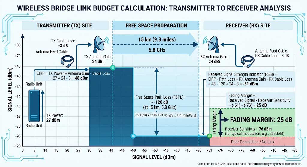
Factors Affecting Transmission Range
Transmission range is determined by the weakest link in the RF chain — not the strongest component. A wireless bridge with a +30 dBm transmitter and -100 dBm receiver sensitivity cannot achieve its theoretical range if the antenna cable introduces 3 dB of loss, which effectively reduces the transmit power by 50% and degrades the received signal by the same amount. Every decibel of loss in cables, connectors, and lightning protectors directly reduces the usable range by approximately 8-12% under typical conditions.
RF Power Output
RF power output is the starting point for any range calculation. Higher transmit power extends range but increases power consumption and may require regulatory compliance management (per FCC Part 15.247 and 15.407[3], EIRP is limited to 36 dBm for point-to-multipoint and 53 dBm for point-to-point in the 5.8 GHz band). A wireless bridge PCBA with adjustable output power from +20 dBm to +30 dBm provides flexibility to trade off range against power consumption. For a solar-powered deployment, reducing transmit power from +30 dBm to +23 dBm lowers RF power consumption while only reducing range by approximately 40-50% — often an acceptable tradeoff for remote battery-operated bridges.
Receiver Sensitivity
Receiver sensitivity is the most commonly misunderstood specification in wireless bridge range calculations. Sensitivity varies significantly with modulation rate — a radio might have -92 dBm sensitivity for 64-QAM (supporting 200-250 Mbps) but only -84 dBm for 256-QAM (supporting 350-400 Mbps). The 8 dB sensitivity difference means that 256-QAM links have approximately 40% less range than 64-QAM links under identical conditions. Adaptive modulation systems automatically step down to more robust modulation (64-QAM → 16-QAM → QPSK → BPSK) as the signal degrades with distance, maintaining connectivity at lower throughput rather than dropping the link entirely. For long-range wireless bridges deployed at maximum distance, the actual throughput may be 25-50% of the theoretical maximum due to the modulation stepping required to maintain the link.
Antenna Gain
Antenna gain is the most cost-effective way to extend range — doubling antenna gain (adding 3 dB) costs $20-50 for a directional antenna, while achieving the same range improvement through increased transmit power would require a more expensive radio and 2-3x higher power consumption. However, higher gain antennas have narrower beamwidths that make alignment more critical. A 24 dBi parabolic dish has a beamwidth of approximately 8 degrees, meaning that a 1-degree misalignment at 15 km distance results in the signal missing the receiver by 260 meters. Professional installation with a sighting scope or laser alignment tool is essential for high-gain antenna deployments.
Frequency Band Selection
Frequency band selection involves a fundamental tradeoff between range and throughput. Lower frequencies (2.4 GHz) have approximately 3-4 dB less free-space path loss than 5 GHz at the same distance, translating to 25-40% longer range for the same hardware configuration. However, the 2.4 GHz band is significantly more congested in industrial environments due to ubiquitous WiFi, Bluetooth, Zigbee, and microwave oven interference. The 5 GHz band offers cleaner spectrum and wider channels (80/160 MHz vs 20/40 MHz) that support higher throughput. For long-range backbone links where reliability is the primary concern, 2.4 GHz provides better range; for high-capacity links where throughput matters more, 5 GHz is the better choice.
Environmental Conditions
Environmental conditions introduce variable losses that must be accounted for in the link budget. Atmospheric oxygen absorption adds 0.016 dB/km at 5 GHz and 0.008 dB/km at 2.4 GHz — negligible for most links. Rain attenuation adds 0.1-3 dB/km depending on rainfall rate and frequency, following the ITU-R P.838-3 model[1], becoming significant only during heavy downpours for links over 10 km. The most significant environmental factor is Fresnel zone obstruction. The Fresnel zone is the elliptical region around the direct line-of-sight path that must be clear of obstacles for optimal signal propagation. For a 15 km link at 5.8 GHz, the Fresnel zone radius at the midpoint is approximately 14 meters — meaning any trees, buildings, or terrain within 14 meters of the direct line-of-sight path will cause signal attenuation, as defined by ITU-R P.526 propagation by diffraction models[2]. A rule of thumb: 20% Fresnel zone obstruction causes approximately 6 dB of additional path loss, reducing range by approximately 25%.
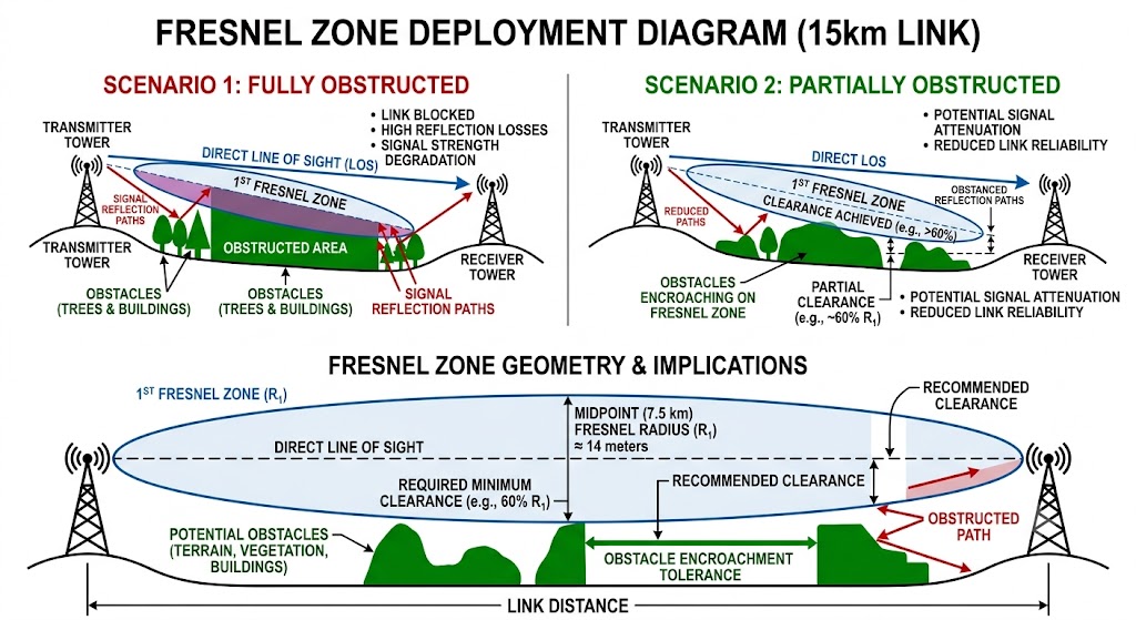
Antenna Selection Guide
Antenna selection is the single most impactful decision in a long-range wireless bridge deployment — the right antenna can double the achievable range without any other hardware changes. The selection involves trading off gain (which determines range) against beamwidth (which determines alignment tolerance and multipath immunity). The table below shows the standard antenna types and their typical performance characteristics for wireless bridge applications.
| Antenna Type | Gain | Beamwidth | Recommended Range | Best For |
|---|---|---|---|---|
| Panel Directional | 12-18 dBi | 30-60 degrees | 5-10 km | Medium-range PTP links with moderate alignment tolerance |
| High-Gain Panel | 18-24 dBi | 15-25 degrees | 10-15 km | Long-range PTP links with precise alignment capability |
| Parabolic Dish | 24-30 dBi | 5-10 degrees | 15-20+ km | Very long-range backbone links with professional installation |
| Omnidirectional | 5-8 dBi | 360 degrees horizontal | 1-3 km | PTMP applications, base stations serving multiple remotes |
The choice between panel and parabolic antennas at long ranges depends on the installation environment and available alignment precision. Panel antennas with 18-24 dBi gain offer a practical balance of range and ease of installation for most 10-15 km links. Their 15-25 degree beamwidth provides some tolerance for wind-induced mast movement and thermal expansion of mounting structures. Parabolic dishes with 24-30 dBi gain are required for 15-20+ km links, but their narrow beamwidth demands rigid mounting structures — a steel mast with 2-inch diameter minimum, concrete foundation at least 1 meter deep, and turnbuckle guy wires for masts over 6 meters tall. For any link beyond 10 km, we recommend using a sighting scope or laser rangefinder for antenna alignment rather than relying on signal strength readings alone.
Real-World Distance Benchmarks
These benchmarks represent achievable real-world performance under good line-of-sight conditions with proper installation. Actual results vary based on Fresnel zone clearance, atmospheric conditions, and interference levels at the deployment site. The throughput figures assume adaptive modulation — as range increases, the radio steps down to more robust modulation, reducing throughput while maintaining link stability.
| Configuration | Expected Range | Typical Throughput | Fade Margin |
|---|---|---|---|
| WiFi 6 + 18 dBi antenna | 10-12 km | 150-300 Mbps | 10-15 dB |
| WiFi 6 + 24 dBi antenna | 15-18 km | 100-250 Mbps | 8-12 dB |
| WiFi 6 + 24 dBi dish antenna | 18-20+ km | 50-150 Mbps | 6-10 dB |
Note that as range increases, throughput decreases due to adaptive modulation stepping down to maintain link stability. At maximum range (18-20+ km), the link typically operates at 16-QAM or QPSK modulation, which provides robust connectivity at reduced data rates. For applications requiring both long distance and high throughput, intermediate repeater stations can divide the link into shorter segments, allowing each segment to operate at higher modulation rates.
Anti-Interference Solutions for Long Range Industrial Wireless Bridge
Section summary: This section identifies common industrial interference sources (VFDs, motors, radar, co-channel WiFi) and provides mitigation strategies. Three-layer approach: (1) spectrum selection via DFS, (2) physical mitigation through separation and shielding, (3) technology features like beamforming and MIMO. Expected improvement: 3-5x throughput gain in congested environments.
Interference is the single most common cause of wireless bridge performance degradation in industrial environments, accounting for approximately 60% of all connectivity issues reported in field deployments. Unlike consumer environments where interference sources are relatively predictable (neighbor WiFi networks, Bluetooth devices), industrial environments contain a diverse and often unpredictable mix of interference sources that can appear and disappear as equipment is turned on and off throughout the workday. A wireless bridge link that performs perfectly at 2:00 AM during testing may show 50% throughput reduction at 10:00 AM when nearby machinery is operating at full capacity.
DFS Channel Selection Strategy
DFS (Dynamic Frequency Selection) is a regulatory mechanism defined in IEEE 802.11h that allows wireless devices to operate on 5 GHz channels shared with radar systems. When radar signals are detected, the device must vacate the channel within 10 seconds and select a different channel. DFS provides access to channels 52-64 and 100-144 (255 MHz of spectrum) that are typically free from consumer WiFi congestion, making them the preferred choice for Long Range Industrial Wireless Bridge deployments. The main tradeoff is that radar detection events can cause brief connectivity interruptions, particularly near airports, military installations, and coastal areas.
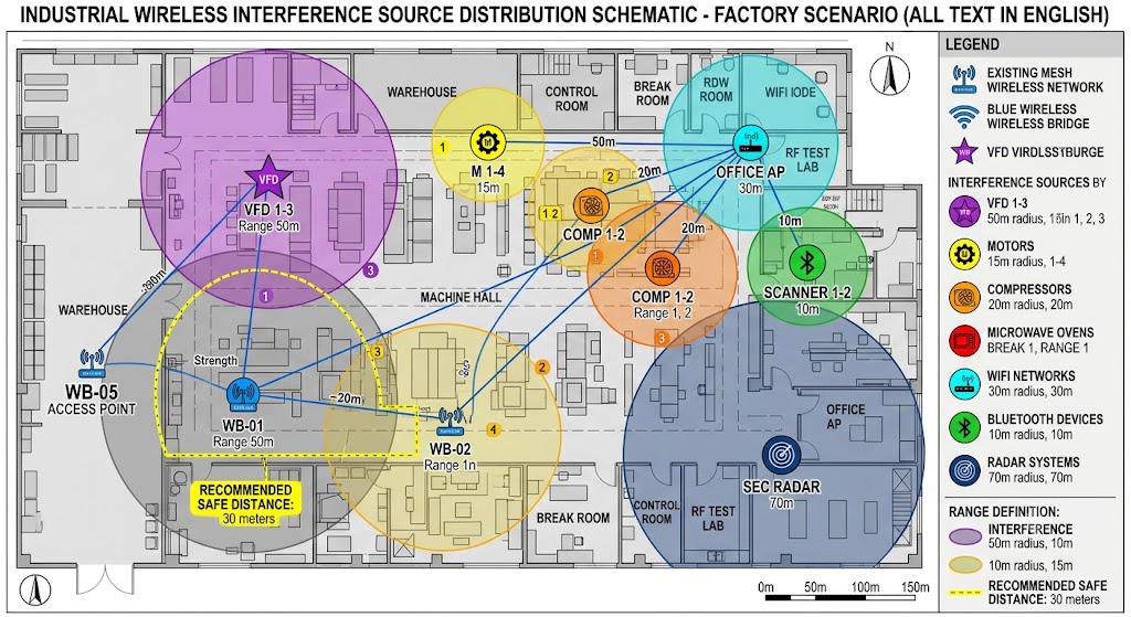
Common Interference Sources
Understanding the specific interference sources in your deployment environment is the first step in designing an effective anti-interference strategy. The industrial interference landscape includes both intentional RF emitters (other wireless systems operating in the same band) and unintentional emitters (electrical equipment that generates wideband noise). Each type requires different mitigation approaches.
Electrical equipment — particularly variable frequency drives (VFDs), motors, pumps, and compressors — generates broadband electrical noise from 10 kHz to 1 GHz. VFDs are the most problematic: their high-frequency switching circuits (typically 4-16 kHz PWM frequency) generate harmonics that extend into the 2.4 GHz and 5 GHz bands. A single 50 HP VFD can generate noise floor elevation of 5-10 dB within a 50-meter radius, significantly reducing the SNR of any wireless link in the area. Mitigation requires physical separation (minimum 30 meters between VFD and bridge equipment), shielded enclosures for both the VFD and bridge, and power line filtering on the bridge’s PoE injector.
Other wireless networks operating in the same frequency band cause co-channel interference. In industrial environments, this includes: other WiFi networks (internal IT networks, guest networks, visitor devices); Bluetooth devices (sensors, headsets, inventory scanners); Zigbee mesh networks (building automation, lighting control); and cordless phones and microwave ovens operating in the 2.4 GHz band. A spectrum analysis during the site survey should identify all active RF sources and their channel occupancy, allowing the wireless bridge to be configured on a channel with minimal competition. For congested environments, using DFS channels (52-64, 100-144) in the 5 GHz band provides access to spectrum that consumer devices typically avoid, offering cleaner channels for industrial bridge links.
Radar systems present a unique interference challenge in the 5 GHz band. Weather radar, military radar, and airport surveillance radar systems operate in the 5.25-5.35 GHz and 5.47-5.725 GHz bands, which overlap with WiFi DFS channels. When a wireless bridge detects radar signals on its current channel, DFS regulations require it to vacate the channel within 10 seconds and avoid it for 30 minutes. For industrial wireless bridges deployed near coastal areas, airports, or military installations, DFS events can occur multiple times per day, causing brief connectivity interruptions and automatic channel switching. The solution is to configure the bridge on non-DFS channels (149-165 in the 5.8 GHz band) where radar operation is not permitted, accepting the slightly higher congestion from other WiFi networks.
DFS Channel Selection Strategies
DFS channel selection requires a deliberate strategy that balances channel availability, interference levels, and the risk of radar detection events. Simply enabling DFS and letting the bridge auto-select channels can lead to suboptimal performance, as the auto-selection algorithm may choose a channel that becomes crowded or triggers frequent radar events.
For industrial deployments, we recommend a structured approach: during the site survey, perform a 24-hour spectrum analysis to identify all active channels and their utilization patterns. Based on this data, select 2-3 candidate DFS channels (preferably in different DFS bands) that show the lowest baseline noise floor and no radar events during the monitoring period. Configure the bridge to use the primary candidate channel, with automatic failover to the backup channels if radar is detected. Monitor the channel utilization weekly during the first month of operation and adjust the channel plan based on observed patterns. This structured approach typically results in 95%+ channel stability, compared to 60-70% with auto-selection in complex RF environments.
Advanced Anti-Interference Technologies
Modern wireless bridge chipsets incorporate several advanced technologies that provide active interference rejection, going beyond passive avoidance strategies. These technologies work at the physical and MAC layers to maintain link quality even in the presence of significant interference.
| Technology | How It Works | Benefits |
|---|---|---|
| Beamforming | Focuses signal in specific direction | Improves signal strength, reduces interference |
| Adaptive Modulation | Automatically adjusts modulation scheme | Maintains connection under interference |
| MIMO | Multiple antennas for diversity | Improves reliability and throughput |
| Error Correction | Forward error correction algorithms | Recovers corrupted data |
Beamforming (explicit transmit beamforming per 802.11ac/ax) uses channel state information from the receiver to adjust the phase and amplitude of each transmit antenna’s signal, creating constructive interference at the receiver’s location. This provides 3-6 dB of signal-to-noise ratio improvement at the receiver, which translates to 25-50% range extension or equivalent interference margin. For point-to-point wireless bridge links with fixed endpoints, beamforming is particularly effective because the channel characteristics are relatively stable, allowing the beamforming pattern to converge and maintain optimal performance.
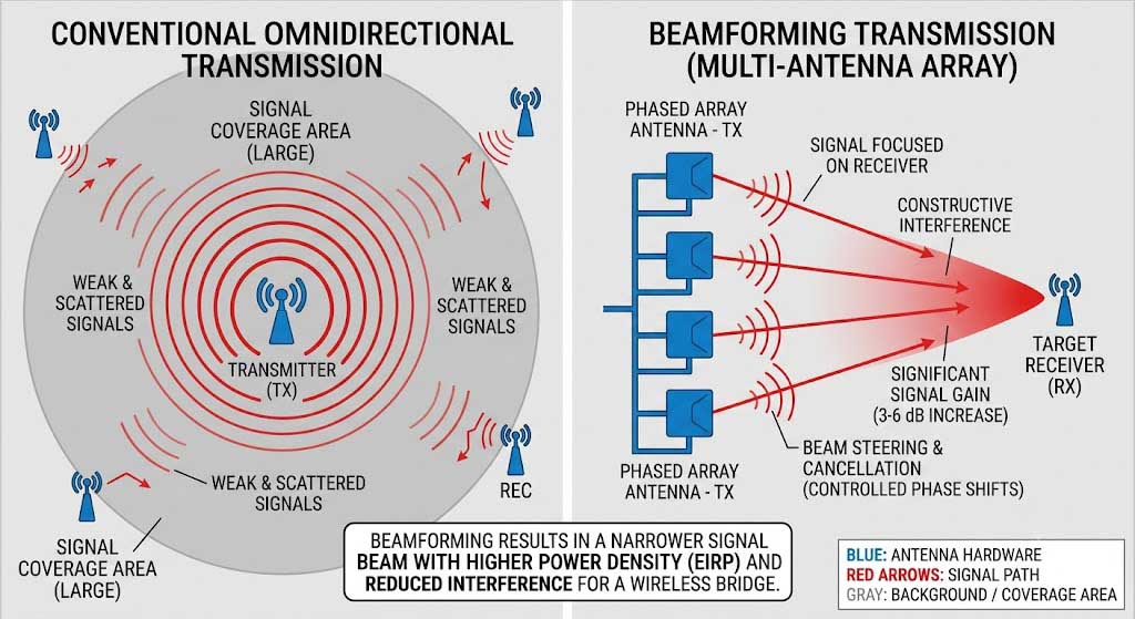
MIMO (Multiple Input Multiple Output) with spatial diversity uses multiple antennas and RF chains to exploit multipath propagation — the reflection of signals off buildings, terrain, and structures. In a 2×2 MIMO system, the two receive antennas each see a different combination of the transmitted signals due to their physical separation (typically 0.5-1 wavelength). The MIMO decoder uses these differences to recover the original transmitted data even when each individual antenna’s signal is corrupted by interference. In environments with strong multipath (reflective surfaces like metal buildings, water towers), MIMO can improve SNR by 5-10 dB compared to a single-antenna system.
Shielding and Grounding Techniques
Proper shielding and grounding are often overlooked but can make the difference between a reliable link and a problematic one in high-interference environments. The goal of shielding is to prevent external electromagnetic fields from coupling into the bridge’s internal electronics and RF circuitry. The goal of grounding is to provide a low-impedance path for interference currents to flow to earth rather than through sensitive electronics.
RF shielding should be applied at multiple levels: the bridge enclosure should be metal (not plastic) with conductive gaskets at all seams and covers to provide continuous shielding effectiveness of 60+ dB. Ethernet cables should be shielded (STP or SFTP) with the shield bonded to ground at both ends — unshielded cables act as antennas that can pick up interference and conduct it into the bridge’s Ethernet PHY. For PoE-powered bridges, the power supply should include common-mode filtering that rejects interference on the DC power lines. In extreme interference environments (near VFDs, welding equipment, or radio transmitters), additional ferrite chokes on both Ethernet and power cables can provide 10-20 dB of common-mode noise suppression.
Grounding for wireless bridge installations should follow the single-point grounding principle: all equipment (bridge, antenna mast, surge protectors, PoE injector) should connect to a single ground reference point, typically a ground rod driven at least 2.4 meters into the earth with resistance to ground of 10 ohms or less per IEEE standards. Multiple ground connections at different potentials create ground loops that can inject 50/60 Hz hum and transient voltages into the equipment. For antenna masts, the mast should be bonded to the grounding system with a minimum 6 AWG copper conductor, and the antenna coaxial cable should include an in-line lightning arrestor with gas discharge tube (GDT) that provides transient protection without adding significant RF loss (typically 0.1-0.3 dB insertion loss).
Troubleshooting Guide for Long Range Industrial Wireless Bridge
Section summary: Systematic three-layer troubleshooting approach: physical layer (cables, power, connectors), RF layer (RSSI, interference, alignment), configuration layer (channels, firmware, QoS). 80% of issues are physical or RF-related. Key diagnostic tools: RSSI meter, spectrum analyzer, link budget calculator.
Most wireless bridge issues fall into one of three categories: physical layer problems (cables, connectors, power), RF problems (interference, alignment, range), or configuration problems (channel selection, firmware, QoS settings). The key to efficient troubleshooting is correctly identifying which category the issue belongs to before diving into detailed diagnosis. Applying RF analysis techniques to a power supply problem — or vice versa — wastes time and can lead to incorrect conclusions.
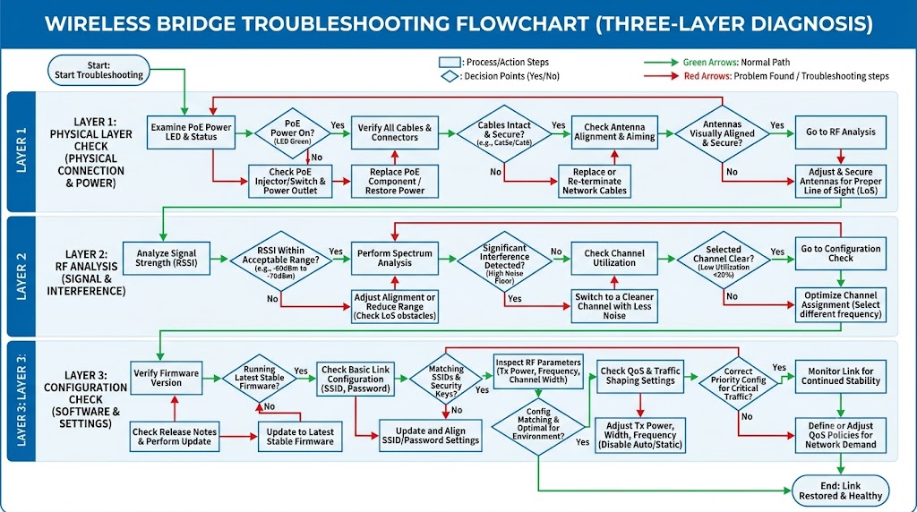
Connection Dropout Diagnosis
Intermittent connection dropouts are the most common complaint in long-range wireless bridge deployments and are almost always caused by one of three factors: power instability, intermittent interference, or marginal link budget. The first diagnostic step is to identify the pattern: does the dropout occur at the same time each day (suggesting a periodically operating interference source like a radar system or shift-change equipment)? Does it correlate with weather events (rain, fog, wind)? Does it happen under specific load conditions (high throughput triggering a power supply voltage drop)?
The systematic diagnosis sequence is: (1) Check physical connections — Ethernet cables, PoE injectors, antenna connectors — with visual inspection and continuity testing. Loose or corroded connectors account for approximately 30% of all dropout issues. (2) Verify signal strength using the bridge’s RSSI reading. A stable RSSI reading of -60 dBm or better with less than 3 dB variation indicates adequate signal level. Fluctuating RSSI suggests antenna misalignment (wind-induced movement), Fresnel zone obstruction (foliage growth), or interference. (3) Use a spectrum analyzer to monitor the channel for 15-30 minutes, looking for intermittent interference sources. (4) Review system logs for error messages — repeated DFS events, Ethernet link drops, or watchdog timer resets each point to specific root causes.
Throughput Degradation Analysis
Throughput degradation without complete connection loss typically indicates either channel congestion, adaptive modulation stepping, or a hardware bottleneck in the Ethernet or processing chain. The distinction from dropout issues is important: throughput degradation can often be resolved through configuration changes rather than physical intervention.
The diagnostic approach for throughput issues focuses on identifying the bottleneck. Start by measuring throughput at different times of day — if throughput is good at 3:00 AM but poor at 3:00 PM, channel congestion or interference is the likely cause. Use the bridge’s built-in spectrum analyzer or channel utilization report to check if the channel is busy. If channel utilization exceeds 50%, consider moving to a cleaner DFS channel or increasing channel width to improve spectral efficiency. Check the modulation rate reported by the bridge — if the link has stepped down from 256-QAM to 64-QAM or lower, the issue is marginal SNR that can be addressed by antenna realignment or gain increase. Finally, verify that the Ethernet connection between the bridge and the network switch is operating at gigabit speed and full duplex — a fallback to 100 Mbps or half-duplex can create a throughput bottleneck even when the wireless link is performing well.
Common Error Codes and Solutions
Error codes and symptoms provide specific diagnostic clues when interpreted in the context of the deployment environment. The table below lists the most common error patterns observed in industrial wireless bridge deployments and their typical root causes.
| Error/Issue | Possible Cause | Solution |
|---|---|---|
| Low RSSI | Antenna misalignment, distance, obstacles | Realign antennas, check line-of-sight |
| High latency | Interference, congestion, distance | Change channel, reduce distance |
| Connection drops | Power issues, interference, firmware bugs | Check power supply, update firmware |
| Slow throughput | Channel width, antenna gain, interference | Use wider channels, higher gain antennas |
For Low RSSI (Received Signal Strength Indicator) readings below -75 dBm, the first check should be antenna alignment. Even a 2-3 degree misalignment with a 24 dBi dish antenna can cause 5-10 dB of signal loss. Use the bridge’s RSSI meter with fine-adjustment of antenna position (0.5 degree increments) to find the peak signal. If the peak RSSI is still below -75 dBm, calculate the link budget to verify that the hardware configuration supports the required distance. A common finding is that the installed antenna cable is longer than specified, adding 2-5 dB of unexpected loss that degrades the link from adequate to marginal.
High latency (above 20-30 ms for a single wireless hop) is typically caused by either channel congestion (the bridge is waiting for the channel to become free before transmitting) or retransmissions (packets are corrupted by interference and must be re-sent). Check the channel utilization percentage and packet error rate from the bridge’s status page. Channel utilization above 60% points to congestion; packet error rate above 5% points to interference. High latency from congestion can be resolved by moving to a less crowded channel or implementing QoS to prioritize critical traffic. High latency from interference requires physical mitigation (shielding, relocation) or technology upgrades (MIMO, beamforming).
Hardware Failure Indicators
Hardware failures are less common than configuration or environmental issues but are more serious when they occur. The key diagnostic indicators that point to hardware failure rather than operational issues include: (1) The bridge fails to power on or boot completely (LED sequence stops at a specific point that indicates a hardware initialization failure); (2) RSSI readings are normal but the bridge cannot associate with its peer (pointing to a MAC/PHY layer hardware fault rather than an RF issue); (3) The bridge operates normally when cool but fails when the enclosure temperature exceeds a specific threshold (indicating a thermal-related component failure); (4) Physical damage such as cracked PCB, corroded connectors, or water ingress in the enclosure.
When hardware failure is suspected, the most efficient diagnostic step is to swap the suspect unit with a known-good unit of the same model. If the issue follows the swapped unit, the original unit had a hardware fault. If the issue remains with the replacement unit, the problem is external to that bridge (power, cabling, interference, or peer equipment). This swap test is significantly faster than attempting detailed hardware diagnosis in the field, and in most cases, the defective unit can be returned to the manufacturer for warranty replacement and root cause analysis.
PCBA Motherboard Design for Long Range Industrial Wireless Bridge
Section summary: RF PCB design principles for Long Range Industrial Wireless Bridge motherboards. Covers ground plane design, component separation (analog vs digital), controlled impedance routing (50-ohm traces), decoupling strategies, and environmental protection (IP65, -40°C to +85°C). A well-designed PCBA can deliver 3-6 dB better RF performance vs a poor design — equivalent to 25-50% additional range.
The PCBA motherboard design for a long-range wireless bridge is fundamentally different from a typical consumer WiFi board design. Consumer boards prioritize low cost and compact size, often using 2-layer or 4-layer PCBs with minimal RF optimization. Industrial wireless bridge PCBA must prioritize RF performance, thermal management, and reliability, typically requiring 6-12 layer boards with controlled impedance, dedicated RF ground planes, and careful partitioning between analog and digital sections. The additional design complexity adds 20-40% to the PCBA cost but delivers 50-100% improvement in RF performance — a worthwhile investment for a bridge that must maintain a reliable link at 15-20 km distance.
RF Design Best Practices
The RF section of a wireless bridge PCBA is the most design-critical part, where even small layout errors can degrade performance by 3-10 dB. The RF signal chain — from the chipset RF pins through the matching network, bandpass filters, power amplifier, and antenna connector — must be treated as a transmission line system where every millimeter of trace and every component placement affects the final performance.
Ground plane design is the foundation of RF PCB layout. A solid, uninterrupted ground plane on the layer directly below the RF signal layer provides the controlled impedance reference that RF traces require. For 50-ohm microstrip traces on a standard FR-4 or high-frequency laminate, the trace width to ground plane spacing ratio must be calculated and verified with field solvers to ensure the characteristic impedance stays within 5% of 50 ohms across the frequency range (2.4-6 GHz). Any discontinuities in the ground plane — such as slots for via clearance or route channels — create impedance mismatches that cause signal reflections and power loss. A single 10% impedance mismatch can cause 0.5 dB of insertion loss, and multiple mismatches along the signal chain accumulate.
Component placement must physically separate the analog RF section from the digital processing section to prevent digital switching noise from coupling into the sensitive RF circuits. Digital circuits — CPU cores, Ethernet PHYs, memory interfaces — generate broadband noise from 10 MHz to 1 GHz through their high-speed switching. If this noise couples into the RF power supply lines or radiates into the RF section, it raises the noise floor at the receiver and degrades sensitivity. A good layout has a clear physical separation with the RF section occupying one area of the board and the digital section in another, with a grounded copper barrier (a “fence” of ground vias) between them. The power supply for the RF section should be regulated with low-noise LDOs that provide 60+ dB power supply rejection at frequencies up to 1 MHz.
Controlled impedance trace routing is essential for all high-frequency signals. The RF traces from the chipset to the antenna connector must maintain 50-ohm characteristic impedance, with no sharp 90-degree corners (use 45-degree chamfered corners or curved traces instead) and no via stubs that create impedance discontinuities. For differential signal pairs (USB, Ethernet, PCI Express), the differential impedance must be maintained at 100 ohms with matched trace lengths within 1 mm to prevent skew that causes common-mode radiation and signal degradation. Trace length matching is particularly important for MIMO systems where the phase relationship between multiple RF chains affects beamforming and spatial multiplexing performance.
Decoupling capacitors must be placed strategically to provide a low-impedance power supply across a wide frequency range. Each IC power pin requires a combination of bulk capacitance (10-100 µF) for energy storage during transient load changes, mid-frequency capacitance (0.1-1 µF) for reducing power supply impedance at 1-100 MHz, and high-frequency capacitance (10-100 pF) for suppressing noise above 100 MHz. The placement of these capacitors relative to the IC power pins is critical — the high-frequency capacitors must be within 2 mm of the power pin with direct via connections to the ground plane, or their effectiveness is significantly reduced by the inductance of long traces.
Recommended Zukaka PCBA Solutions
Zukaka’s PCBA platforms are designed with these RF best practices built in, providing a proven foundation for long-range wireless bridge development. Each platform uses a 6-layer or 8-layer PCB stackup with dedicated RF ground planes, high-frequency laminate materials for the RF signal layers, and extensive decoupling on all power rails. The layout partitioning follows the best practices described above, with physical separation between RF and digital sections and grounded via fences at the partition boundaries.
- 11ac 24V Gigabit Wireless Bridge PCBA: Ideal for medium-range applications (5-10 km) with 24V PoE input, IP65 rating, and industrial temperature range. The 6-layer PCB with Rogers 4003C high-frequency laminate provides excellent RF performance at a cost-effective price point for medium-volume deployments.
- 11ac 48V Long-Range Bridge PCBA: Optimized for long-range (10-30 km) with 48V PoE input supporting longer cable runs, higher transmit power capability, and enhanced thermal management for sustained high-power operation. The 8-layer PCB with multiple ground planes provides superior signal integrity for the highest RF performance.
- 5GHz PTP/PTMP Wireless Bridge PCBA: Supports both point-to-point and point-to-multipoint modes with RouterOS firmware, providing flexible topology options. The dual-chain RF design supports 2×2 MIMO with beamforming for enhanced range and interference rejection.
Environmental Protection Features
Environmental protection is not optional for outdoor wireless bridges — it is a fundamental requirement that directly affects product lifespan and field reliability. The table below shows the key environmental specifications and their importance for long-term outdoor deployment.
| Feature | Specification | Importance |
|---|---|---|
| Temperature range | -40°C to +85°C | Critical for outdoor industrial use |
| Humidity resistance | IP65 or higher | Prevents moisture damage |
| EMC compliance | FCC Part 15, CE RED | Reduces interference |
| Surge protection | ESD protection circuits | Protects against electrical spikes |
The industrial temperature range of -40°C to +85°C is required for wireless bridges deployed in unenclosed outdoor locations. At -40°C, the board must survive thermal shock during power-up, when internal self-heating causes rapid temperature rise while the board is still at extreme cold. At +85°C, the components must operate without thermal shutdown while the PCBA is heated by both self-heating (8-15W chipset dissipation) and solar radiation (which can add 15-25°C to the internal temperature of a dark-colored enclosure). The solder joints must withstand the thermal expansion differential between the PCB (CTE of 14-17 ppm/°C for FR-4) and ceramic IC packages (CTE of 6-8 ppm/°C) across 1000+ thermal cycles over the product’s lifetime.
IP65 (Ingress Protection) rating ensures the bridge is protected against dust ingress and low-pressure water jets from any direction. For wireless bridges deployed in coastal or chemical plant environments, IP67 (full dust protection and temporary water immersion) is recommended, along with conformal coating of the PCBA that provides a protective layer against salt spray, chemical vapors, and conductive contamination. The conformal coating adds $1-3 per board but can extend the product’s field life by 2-3 years in corrosive environments.
Deployment Best Practices for Long Range Industrial Wireless Bridge
Section summary: End-to-end deployment methodology covering site survey (spectrum analysis, Fresnel zone verification), professional installation (grounding, lightning protection, antenna alignment), and maintenance schedule. Proper deployment can mean the difference between 100% specified performance vs 30-50% underperformance.
The most carefully designed wireless bridge PCBA will perform poorly if the deployment is not properly executed. Unlike consumer WiFi devices that are designed to work with minimal installation effort, long-range wireless bridges require professional deployment practices to achieve their full performance potential. The effort invested in proper deployment — typically 1-3 days for a single point-to-point link — directly determines the link’s reliability, throughput, and lifespan.
Site Survey Checklist
A comprehensive site survey is the single most important step in the deployment process, as it identifies issues that cannot be corrected after installation. The survey should verify the following before any equipment is mounted or cables are run. Each item checked off represents a potential problem avoided.
- Line-of-sight verification: Confirm that a clear optical path exists between the two endpoints with no terrain, buildings, or vegetation obstructing the Fresnel zone. Use binoculars or a spotting scope for the initial visual check, then use a laser rangefinder to confirm the exact path. Pay special attention to the midpoint of the link where the Fresnel zone is widest — a tree at the midpoint that appears small from both ends can still obstruct the signal.
- Accurate distance measurement: Measure the straight-line distance between endpoints using GPS coordinates and the Haversine formula, or use a laser rangefinder for direct measurement. Do not rely on map-based measurements, which may not account for terrain elevation differences. The measured distance is used for the link budget calculation that determines the required antenna gain and expected throughput.
- Obstacle analysis with Fresnel zone calculation: For each potential obstacle between the endpoints, calculate whether it intrudes into the Fresnel zone. The Fresnel zone radius at any point along the link is calculated using the distance from each endpoint and the operating frequency. Any obstacle within 60% of the Fresnel zone radius will cause measurable attenuation.
- Interference mapping: Use a spectrum analyzer at both endpoints to measure the noise floor across the 2.4 GHz and 5 GHz bands. Identify all active channels and their utilization levels. Note any intermittent interference sources that appear during the monitoring period (typically 30-60 minutes per endpoint).
- Power availability verification: Confirm that the required power source is available at both endpoints — PoE (requires a PoE switch or injector within 100 meters), solar (requires adequate sunlight and battery capacity), or AC power (requires weatherproof outlet and surge protection). For solar-powered sites, verify that the solar panel location receives unobstructed sunlight for at least 5 hours per day year-round.
Installation Guidelines
These installation guidelines represent best practices developed from hundreds of industrial wireless bridge deployments. Following them ensures regulatory compliance, environmental protection, and optimal RF performance from the first day of operation.
- Mount antennas at sufficient height to clear Fresnel zone obstacles: The minimum height is typically 10-30 meters above ground level depending on the link distance and terrain. For a 15 km link at 5.8 GHz, antennas should be mounted at least 14 meters above any obstacles at the midpoint. Use a telescoping mast or tower section that can be adjusted to the calculated height, with guy wires for stability on masts over 6 meters.
- Install lightning protection on all cables: Coaxial lightning arrestors with gas discharge tubes should be installed on antenna cables at the point where they enter the building or enclosure. Ethernet surge protectors should be installed on all PoE cables before they connect to indoor equipment. All surge protectors must be bonded to the grounding system with conductors no longer than 1 meter to ensure effective transient protection.
- Implement single-point grounding: Connect all equipment — antenna masts, bridge enclosures, surge protectors, power supplies — to a single ground reference point. The ground rod should be driven to achieve less than 10 ohms resistance to earth. Use 6 AWG or larger copper wire for ground conductors and ensure all connections are made with irreversible compression connectors, not screw terminals that can loosen over time.
- Test connectivity and throughput before finalizing installation: With the equipment temporarily mounted and powered, verify the link establishes and measure RSSI, SNR, and throughput. RSSI should be -60 dBm or better for reliable operation. If RSSI is below -70 dBm, check antenna alignment and cable losses before finalizing the installation.
- Document all configuration settings: Record IP addresses, channel settings, antenna type and gain, cable lengths, firmware version, and all configuration parameters. This documentation is essential for troubleshooting future issues and for replicating the configuration on replacement equipment.
Maintenance Schedule
A maintenance schedule ensures that performance degradation is detected early, before it causes a link failure. The schedule below is based on typical industrial deployment conditions; sites in extreme environments (coastal salt spray, desert dust, arctic ice) may require more frequent inspections.
| Task | Frequency | Purpose |
|---|---|---|
| Visual inspection | Monthly | Check for damage, corrosion |
| Signal quality check | Quarterly | Monitor RSSI, throughput |
| Firmware update | Semi-annually | Security patches, bug fixes |
| Antenna alignment check | Annually | Verify alignment hasn’t shifted |
The monthly visual inspection should check for: physical damage to the enclosure (cracks, dents), corrosion on connectors and ground bonding points, condensation inside the enclosure, and any vegetation growth near the antenna path that could begin to obstruct the Fresnel zone. The quarterly signal quality check should compare current RSSI and throughput readings against the baseline measurements taken during installation. A gradual decrease of more than 3 dB in RSSI over successive quarters suggests antenna misalignment (from wind or mast settling), Fresnel zone obstruction (from foliage growth), or component degradation.
Recommended Long Range Industrial Wireless Bridge PCBA Products
Section summary: Zukaka’s PCBA product lineup for different range and topology requirements. Four platforms: 11ac 48V (flagship, 15-30km), Dual-Port 48V (redundant links, 15-30km), 5GHz PTP/PTMP (flexible topology, 5-15km), 11n 24V (cost-optimized, harsh environments). Selection guide based on range, topology, and power requirements.
The four PCBA platforms below represent Zukaka’s proven solutions for Long Range Industrial Wireless Bridge applications. Each platform is a complete motherboard design that integrates the wireless chipset, RF front-end, power management, Ethernet interface, and firmware — requiring only an enclosure, antenna, and power source to create a functioning wireless bridge. The selection should be guided by the range requirement, deployment topology, and environmental conditions of the specific project.
| Product | Key Specifications | Best For |
|---|---|---|
| 11ac 48V Long-Range Bridge PCBA | 500+ Mbps, 30km PTP, 48V PoE, IP65, -40°C to +75°C | Ultra-long range (15-30km), oil pipelines, power line monitoring |
| 11ac Dual-Port 48V Bridge PCBA | 500+ Mbps, dual gigabit ports, 30km range, 48V PoE | Redundant links, critical infrastructure, dual-camera sites |
| 5GHz PTP/PTMP Wireless Bridge PCBA | 27dBm EIRP, RouterOS, flexible topology, 5-15km | Point-to-multipoint, campus connectivity, hotspot coverage |
| 11n 24V Wireless Bridge PCBA | IP65, 29dBm TX, iPoll protocol, -40°C to +65°C | Harsh environments, legacy systems, cost-effective solutions |
The 11ac 48V Long-Range Bridge PCBA is the flagship product for the most demanding long-distance applications. Its 48V PoE input supports cable runs up to 100 meters with standard Cat5e, providing deployment flexibility for tower-mounted installations where power outlets are unavailable. The board implements Qualcomm’s 802.11ac chipset with 2×2 MIMO and beamforming, delivering 500+ Mbps real-world throughput at 10 km and maintaining reliable connectivity at 30 km with appropriate antenna configuration. The IP65-rated design and industrial temperature range make it suitable for direct outdoor mounting without an additional enclosure, reducing installation complexity and cost.
The 11ac Dual-Port 48V Bridge PCBA adds a second gigabit Ethernet port that provides redundancy and flexibility for critical infrastructure applications. The dual ports can be configured for: port aggregation (combining both ports for 2 Gbps throughput to the connected device); redundant links (automatic failover if the primary connection fails); or pass-through connectivity (connecting two devices at the remote site through the bridge). This product is the recommended choice for applications where link reliability is the highest priority, such as connecting remote SCADA systems, monitoring stations, or security checkpoints where a single point of failure in the network connection is unacceptable.
The 5GHz PTP/PTMP Wireless Bridge PCBA distinguishes itself by supporting both point-to-point and point-to-multipoint topologies through its RouterOS firmware. A single PTMP base station can serve up to 10-15 remote clients within a 60-120 degree sector, making this platform ideal for campus networks, temporary event connectivity, and coverage expansion for existing wired infrastructure. The flexibility of RouterOS provides advanced features including VLAN segmentation, QoS bandwidth management, firewall rules, and VPN termination — capabilities that are typically found in enterprise-grade networking equipment but are integrated directly into the wireless bridge PCBA.
The 11n 24V Wireless Bridge PCBA is the cost-optimized solution for applications where 802.11n (300-450 Mbps PHY rate) provides sufficient throughput. Its 29 dBm transmit power and proprietary iPoll protocol provide excellent range and interference tolerance, making it a popular choice for harsh environments where deployment conditions are challenging. The lower power consumption of the 11n chipset (typically 6-8W vs 10-15W for 11ac) makes this platform the preferred choice for solar-powered installations where minimizing power consumption is critical.
Frequently Asked Questions About Long Range Industrial Wireless Bridge
Q: What is the maximum reliable distance for industrial wireless bridges?
With proper antenna configuration (18-24 dBi directional antennas) and clear line-of-sight with Fresnel zone clearance, a Long Range Industrial Wireless Bridge can achieve reliable transmission up to 20 km. Under ideal conditions with high-gain dish antennas (24-30 dBi) and optimized link budgets, distances up to 30 km are possible. However, the achievable throughput decreases with distance as adaptive modulation steps down to maintain the link — a 30 km link typically delivers 50-150 Mbps compared to 300-500 Mbps at 10 km. For applications requiring both long distance and high throughput, consider using a higher-performance bridge PCBA with larger antennas or intermediate repeater stations that divide the link into shorter segments.
Q: How do I choose between 2.4GHz and 5GHz for long-range applications?
5 GHz is generally preferred for Long Range Industrial Wireless Bridge applications due to significantly less interference and wider channel bandwidth, despite having 3-4 dB higher free-space path loss than 2.4 GHz. The higher path loss at 5 GHz can be compensated with 1-2 dB of additional antenna gain, which is easily achieved with the same physical antenna size (a 24 dBi antenna at 5.8 GHz is physically smaller than a 24 dBi antenna at 2.4 GHz). The key advantage of 5 GHz is spectrum availability — the 5 GHz band provides 580 MHz of spectrum (channels 36-165) compared to 80 MHz in 2.4 GHz (channels 1-11), with DFS channels in 5 GHz offering clean spectrum that is typically free from the congestion and interference that plagues 2.4 GHz in industrial environments.
Q: What is DFS and why is it important?
Dynamic Frequency Selection (DFS) is a regulatory mechanism that allows wireless devices to operate on 5 GHz channels that are shared with radar systems, by detecting radar signals and automatically vacating the channel within 10 seconds. DFS provides access to channels 52-64 and 100-144 (a total of 255 MHz of spectrum) that are not available to non-DFS devices. For industrial wireless bridges deployed in areas without active radar systems, DFS channels offer the cleanest spectrum with minimal interference from consumer WiFi devices, because most consumer access points and routers do not support DFS and cannot use these channels. The tradeoff is that radar detection events can cause brief connectivity interruptions (the 10-second channel vacate time plus 30-minute channel non-occupancy period). For deployments near airports, military installations, or coastal areas with radar coverage, we recommend evaluating radar activity during the site survey and using non-DFS channels (149-165) if DFS events are frequent.
Q: How can I improve signal strength for my wireless bridge?
Improving signal strength requires a systematic approach that addresses the RF link from the transmitter through the propagation path to the receiver. The most impactful actions, in order of effectiveness: (1) Use higher-gain antennas — replacing a 18 dBi panel with a 24 dBi dish provides 6 dB of gain improvement, effectively doubling the range or providing equivalent fade margin. (2) Ensure perfect antenna alignment using a sighting scope or laser alignment tool — even 1-2 degrees of misalignment with a high-gain antenna can cause 3-6 dB of signal loss. (3) Minimize cable and connector losses — replace long antenna cables with shorter runs or lower-loss cable types (LMR-400 instead of RG-58 can reduce cable loss by 50-70%). (4) Implement DFS channel selection to find the channel with the lowest noise floor, providing 3-8 dB of SNR improvement compared to crowded channels. (5) Verify Fresnel zone clearance and trim or raise antennas to clear any obstructions.
Q: What is the typical lifespan of an industrial wireless bridge?
With proper installation, regular maintenance, and stable power quality, industrial wireless bridges typically have a service life of 5-7 years before performance degradation or component failure becomes likely. The primary aging factors are: electrolytic capacitor degradation in the power supply (capacitors lose capacitance and increase ESR over time, particularly at high temperatures); solder joint fatigue from thermal cycling (which eventually causes intermittent connections); and RF connector corrosion (which increases insertion loss and can cause intermittent connectivity). Proactive replacement at the 5-6 year mark is recommended for mission-critical links where a failure would cause significant operational disruption. Firmware updates should be applied throughout the service life to address security vulnerabilities and improve performance.
Q: How do I troubleshoot intermittent connectivity issues?
Intermittent connectivity issues should be diagnosed by first identifying the pattern of failures, then checking physical connections and power stability, followed by RF analysis. Start by determining whether the issue occurs at specific times (suggesting an interference source on a schedule), during specific weather conditions (suggesting Fresnel zone obstruction or water ingress), or randomly (suggesting power supply issues or hardware degradation). Check the bridge’s event logs for DFS events, Ethernet link flaps, and watchdog resets. Verify the power supply voltage at the bridge’s input connector — PoE voltage drops under load can cause intermittent resets that mimic RF issues. Use the bridge’s built-in spectrum analyzer or an external analyzer to monitor the channel for intermittent interference. If the issue correlates with specific equipment operation (like a compressor or pump starting), RF interference from that equipment is the probable cause and physical relocation or shielding is the solution.
Q: Can wireless bridges work without line-of-sight?
While some non-line-of-sight (NLOS) communication is possible through signal reflections and diffraction, reliable long-distance wireless bridge transmission typically requires clear line-of-sight with Fresnel zone clearance. NLOS links depend on reflected signals, which have significantly higher path loss than direct signals (typically 10-20 dB additional loss) and are subject to fading as reflective surfaces move or change (e.g., vehicles parking, doors opening). For short distances under 2-3 km, NLOS operation may be feasible with sufficient fade margin and lower throughput expectations. For distances beyond 5 km, NLOS is generally not reliable enough for industrial applications where consistent connectivity is required. If line-of-sight is not achievable, consider: raising antenna masts to clear obstacles; selecting an alternative endpoint location with better visibility; or using a relay station at an intermediate point to route around the obstacle.
Q: What power supply options are best for remote wireless bridges?
For remote locations without existing power infrastructure, solar-powered systems with battery storage are the most reliable and cost-effective solution over the product lifecycle. A typical solar-powered wireless bridge installation requires: a 50-200W solar panel (depending on bridge power consumption and local sunlight conditions), a charge controller with MPPT (maximum power point tracking) for optimal charging efficiency, and a battery bank providing 100-200 Ah at 12V or 24V for nighttime and cloudy-day operation. The total system cost for a solar-powered bridge installation is typically $500-2,000 in addition to the bridge equipment itself, with a 3-5 year payback period compared to the cost of running AC power lines. For locations with existing AC power infrastructure, PoE (Power over Ethernet) is the preferred option — our bridge PCBA products support both 24V passive PoE and 48V 802.3af/at standards, allowing power delivery over the same Ethernet cable used for data, simplifying installation and reducing cost.
By: Zukaka Engineering Team |
Last Updated: June 14, 2026 |
Contact our engineering team
The Zukaka Engineering Team specializes in wireless communication hardware design and RF system integration, with over a decade of experience in industrial wireless bridge development. Our team holds multiple patents in antenna design and wireless transmission optimization.
References & Data Sources: All technical specifications (TX power, receiver sensitivity, range figures, throughput benchmarks) in this guide are based on Zukaka product datasheets and industry-standard RF engineering models. Where applicable, data sources are cited below.
- [1] ITU-R P.838-3 — Rain Attenuation Model for Radio Wave Propagation — ITU Recommendation
- [2] ITU-R P.526-15 — Propagation by Diffraction — ITU Recommendation
- [3] FCC Part 15, Subpart C — Intentional Radiators (15.247, 15.407) — eCFR Title 47
- [4] IEEE Std 802.11-2020 — Wireless LAN MAC and PHY Specifications
- [5] RFC 2544 — Benchmarking Methodology for Network Interconnect Devices
Contact our engineering team for customized PCBA solutions and technical support.


