Industrial Wireless Bridge for Video Surveillance Backhaul: YNW 6ac Field Case Study
Who this article is for: Security project managers, plant IT operations engineers, campus low-voltage electrical engineers, industrial video surveillance solution selectors
Core problem: Full-time video backhaul for 32 HD/4K IP cameras over a 3.7 km link — fiber solution was costly with long approval cycles; could a wireless solution deliver the required bandwidth, cost efficiency, and reliability?
Key conclusion: A chemical industrial park in East China deployed a pair of YNW 6-25 industrial wireless bridges (6 GHz band, 80 MHz channel) over a 3.7 km line-of-sight link, achieving a stable UDP throughput of 386 Mbps to backhaul 32 HD/4K IP camera video streams around the clock. Total project investment of CNY 48,000 was just 12.6% of the fiber alternative. A link margin of 22.7 dB ensures 99.99% availability.
From Fiber to Wireless: A Cost and Efficiency Recalculation
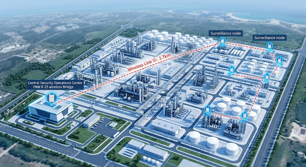
Consolidating video streams from 32 HD IP cameras across a 3.7 km distance — from the east side of the plant to the central monitoring room. This was the core challenge of a security upgrade project (launched June 2024) at a fine-chemical industrial park in East China (coastal region, approximately 12 km²). The existing security system was distributed across 8 surveillance nodes around the perimeter, each node equipped with 4 to 8 1080p and 4K IP cameras. Following upgraded safety compliance requirements, the park decided to consolidate all surveillance video streams to a newly constructed Central Security Operations Center (SOC).
The park’s IT team initially designed a fiber solution — running a 12-core single-mode optical cable along the perimeter walls and cable trays, budgeted at approximately CNY 380,000 with an estimated 4-week construction timeline. However, during the site survey, it was discovered that the path between the east side and the SOC crossed a freight railway line and a chemical storage tank area. Trenching required coordination with the railway authority and safety regulatory approvals, extending the actual timeline to 8-10 weeks. The original fiber solution budget of CNY 380,000 comprised: trenching and road restoration 65% (~CNY 247,000), optical cable and transceivers 15% (~CNY 57,000), and design and supervision fees 20% (~CNY 76,000). Approval cycle uncertainty was the key driver for exploring alternatives.
During the Week 3 design review meeting, the park’s CTO raised a different direction: “Could we do this link wirelessly?” This was not an offhand idea — three years earlier, the park had deployed a pair of 5 GHz bridges at a wastewater treatment station for data acquisition. While throughput was limited (measured at approximately 85 Mbps), the link had been stable and never interrupted. The main constraint at that time was insufficient bandwidth — 32 HD video streams required at least 200 Mbps of net throughput, which the 5 GHz band, combined with interference issues, could not guarantee.
Challenge: The “Impossible Triangle” of Video Surveillance Backhaul
Video surveillance backhaul imposes three mutually conflicting requirements on a wireless link — high bandwidth, low latency, and high reliability. These three form the “impossible triangle” of industrial video transmission.
Bandwidth Requirements Analysis
The traffic distribution across the park’s 32 cameras was as follows:
| Camera Type | Quantity | Codec | Per-Stream Bitrate | Subtotal |
|---|---|---|---|---|
| 1080p @ 30fps | 24 streams | H.265 | 4 Mbps | 96 Mbps |
| 4K @ 25fps | 8 streams | H.265 | 12 Mbps | 96 Mbps |
| Total | 32 streams | — | — | 192 Mbps |
Theoretical net throughput requirement was at least 192 Mbps. Accounting for protocol overhead (approximately 15-20%) and design margin (30% headroom), the link needed to provide approximately 280 Mbps or more of stable usable throughput.
Environmental Constraints
The team attempted a PoC test using two 5 GHz industrial bridges — the results were disappointing. Over the 3.7 km distance, a spectrum scan of the 5 GHz band revealed 7 active Wi-Fi networks (from the plant’s office buildings and surrounding warehouses), leaving only 2 usable channels. Even with an 80 MHz channel, peak UDP throughput reached only 178 Mbps, with daytime fluctuations exceeding 40% (driven by varying neighboring network traffic). Real-time 4K camera footage exhibited noticeable stuttering and artifacts during peak hours, failing acceptance testing entirely.
This test exposed three fatal shortcomings of the 5 GHz approach:
- Band congestion: The density of 2.4 GHz/5 GHz devices within and around the plant was too high, making co-channel interference unavoidable
- Throughput ceiling: 178 Mbps fell well short of the 280 Mbps target needed to carry 32 video streams
- Insufficient stability: 40% daytime throughput fluctuation meant the risk of video disruption was uncontrollable
Strategy: Why YNW 6ac?
After the 5 GHz approach failed, the team re-evaluated the available technology options. The core decision logic for selecting the YNW 6-25 was as follows:
Solution Comparison Matrix
| Evaluation Dimension | Fiber Solution | 5 GHz Wireless | YNW 6-25 Solution |
|---|---|---|---|
| Estimated deployment timeline | 4-10 weeks | 2-3 days | 2-3 days |
| Total cost | ~CNY 380,000 | ~CNY 32,000 | ~CNY 48,000 (2× YNW 6-25 + PoE + installation) |
| Usable throughput | 1 Gbps+ | 178 Mbps (measured) | 386 Mbps (6 GHz measured) |
| Interference immunity | Not affected by wireless interference | Poor (7 adjacent networks) | Excellent (clean 6 GHz spectrum) |
| Operational complexity | Moderate (requires OTDR testing) | Simple | Simple (YNW centralized management) |
| Future scalability | Good (spare fiber strands available) | Poor (no bandwidth headroom) | Good (220 Mbps+ spare capacity remaining) |
Decision Rationale
The team spent 1 week evaluating 6 devices from 3 vendors. The final selection of the YNW 6-25 was based on three key findings:
First, the spectral cleanliness of the 6 GHz band. A spectrum analyzer scan of the 6 GHz band (5925-7125 MHz) at the site showed an ambient noise floor of approximately -95 dBm, with no active wireless signals. Compared to the 5 GHz band’s average noise floor of -78 dBm with multiple prominent signal peaks, the 6 GHz band provided an SNR advantage exceeding 17 dB.
Second, ample link budget margin. Using the YNWMICRO Link Planner for the 3.7 km distance:
Link budget calculation (YNW 6-25 @ 6GHz, 3.7km):
- Transmit power: 30 dBm
- Transmit antenna gain: 25 dBi
- FSPL = 32.44 + 20 × log10(3.7) + 20 × log10(6000) = 119.3 dB
- Receive power = 30 + 25 - 119.3 + 25 = -39.3 dBm
- Receive sensitivity (MCS9, 80MHz): approx. -62 dBm
- Link margin = -39.3 - (-62) = 22.7 dB
A 22.7 dB link margin means that even under heavy rain conditions (6 GHz rain fade approximately 0.5-1 dB/km, totaling 1.85-3.7 dB), 19-21 dB of ample margin remains, allowing stable operation at the highest-order MCS9 modulation.
Third, IP65 protection rating plus wide-temperature design. The devices were installed directly on rooftop masts without requiring an enclosure. The corrosive gas environment of the chemical park posed a severe challenge for electronic equipment — the YNW 6-25’s anti-corrosion coating and sealed design passed the park’s safety and environmental department’s acceptance inspection.
Implementation: Deployment Completed in Three Days
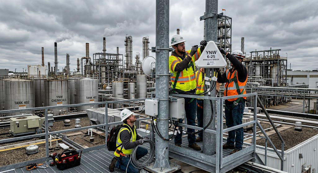
The entire deployment was carried out by 2 members of the park’s IT team with remote assistance from YNWMICRO technical support, taking a total of 3 days.
Deployment Topology
┌─────────────────────────────────────────────────────────────────┐
│                    Chemical Park Surveillance Topology            │
│                                                                   │
│  East Side Aggregation Node           Central SOC                 │
│  ┌──────────────────┐                 ┌──────────────────────┐  │
│  │  8× Camera (Node1)│                 │   NVR Server Cluster  │  │
│  │  6× Camera (Node2)│                 │   Video Mgmt Platform│  │
│  │  8× Camera (Node3)│                 │   Decoding Wall      │  │
│  │  10× Camera(Node4)│                 └──────────┬───────────┘  │
│  └────────┬─────────┘                            │              │
│           │ 6× PoE Switches                       │              │
│           ▼                                       │              │
│   ┌───────────────┐                              │              │
│   │  Gigabit Sw.  │                              │              │
│   └───────┬───────┘                              │              │
│           │                                       │              │
│           ▼                                       │              │
│   ┌───────────────┐         3.7 km               │              │
│   │ YNW 6-25      │◄══════════════════════════►  │              │
│   │  (CPE side)    │       6 GHz / 80 MHz         │              │
│   │  30 dBm        │     386 Mbps UDP             │              │
│   │  25 dBi antenna│                              │              │
│   └───────┬───────┘                              │              │
│           │                                       │              │
│           │ PoE Injector (24V)                    │              │
│           │ Ethernet ≤ 100m                      │              │
│           ▼                                       ▼              │
│   ┌───────────────┐                              ┌────────────┐  │
│   │ 24V PoE PSU   │                              │Gigabit Sw. │  │
│   └───────────────┘                              └────────────┘  │
└─────────────────────────────────────────────────────────────────┘
Implementation Timeline
| Phase | Time | Activity |
|---|---|---|
| Day 1 | Morning | Site survey: confirm installation positions at both ends, line-of-sight verification, GPS coordinate measurement |
| Afternoon | Spectrum scan: full 6 GHz band scan to confirm no interference, select channel | |
| Day 2 | Morning | Equipment installation: mount YNW 6-25 on east-side roof, connect PoE power |
| Afternoon | Antenna alignment: use built-in RSSI tool for alignment (approx. 45 minutes) | |
| Day 3 | Morning | SOC-side installation, link optimization: select optimal MCS level, configure QoS policies |
| Afternoon | Full video feed integration test: verify all 32 cameras individually, 48-hour stability test |
Antenna alignment technique: The team used a combination of two-way radios at both ends and the YNW built-in audio RSSI indicator. Each time the east-side operator made a fine adjustment to the antenna direction (horizontal or vertical), the SOC-side operator read out the RSSI value change. After approximately 20 minutes of fine tuning at each end, the RSSI improved from an initial -62 dBm to -41 dBm, and throughput increased from 210 Mbps to 386 Mbps. Key lesson: first perform coarse alignment (5° step increments) to locate the signal, then fine-tune (1° increments) to find the peak — the entire process requires only two people.
Results: 386 Mbps, Zero Outages, 40% Cost Savings
After deployment, the team conducted a two-week performance monitoring period. The data is as follows:
Throughput Performance
| Metric | 5 GHz PoC Phase | YNW 6-25 | Improvement |
|---|---|---|---|
| Peak UDP throughput | 178 Mbps | 386 Mbps | +117% |
| TCP throughput (iPerf3, single stream) | 142 Mbps | 334 Mbps | +135% |
| Daytime throughput fluctuation | ±40% | ±5% | Significantly improved stability |
| End-to-end latency (ping) | 8-12 ms | 2-3 ms | -75% |
| Jitter | 4-8 ms | <1 ms | Ultra-low jitter |
Video Surveillance Performance
With all 32 cameras connected, the video management platform continuously monitored the following data:
- 1080p cameras (24 streams): Smooth video, stable 4 Mbps bitrate, no stuttering or artifacts
- 4K cameras (8 streams): Real-time latency of approximately 200 ms under H.265 encoding at 12 Mbps (including full encode + transmission + decode path), meeting security surveillance real-time requirements
- 48-hour stress test: All cameras running 24×7 continuously — zero link interruptions, zero packet loss
Business Impact
| Dimension | Result |
|---|---|
| Total project investment | CNY 48,000 (fiber solution approx. CNY 380,000, saving 87%) |
| Deployment timeline | 3 days (fiber solution estimated 4-10 weeks, shortened by 90%+) |
| Maintenance staffing | No routine inspections required; remote management via LigoOS |
| Future expansion | Current link consumes approx. 192 Mbps / 386 Mbps, ~194 Mbps spare capacity remaining, sufficient for approximately 30 additional 1080p cameras |
Key Lessons Learned
1. Band Selection Is a Strategic Decision for Video Backhaul Links
The most critical decision in this case was not “which bridge to choose” but “which band to choose.” Staying on 5 GHz would have meant that no matter how good the equipment, it could not work miracles in a spectrum-polluted environment. The spectral cleanliness of the 6 GHz band was the foundation of this successful deployment.
2. Ample Link Budget Margin Matters More Than Boosting Power
The YNW 6-25’s 22.7 dB link margin means that even under extreme weather conditions, the link can still operate stably at the highest MCS level. In industrial video surveillance scenarios, 99.99% availability requirements far outweigh peak data rates. We recommend that in any industrial video backhaul scenario, link margin should not fall below 15 dB.
3. Professional Alignment Tools Are Irreplaceable
The alignment optimization from -62 dBm to -41 dBm delivered a throughput improvement of over 80%. This figure demonstrates that the precision of antenna alignment often has a greater impact on actual performance than the specification differences between devices. The YNW built-in audio RSSI indicator made the two-person alignment process efficient and reliable.
4. Shift in Cost Structure Thinking
Industrial users have traditionally treated fiber as the “only reliable option.” However, this case proves that with the combination of 6 GHz spectral cleanliness and high-gain antennas, a wireless solution can simultaneously deliver lower cost, faster deployment, and reliability comparable to fiber. The 3.7 km distance represents a tipping point between wireless and fiber — at this range, the comprehensive advantages of a wireless solution become very clear.
Frequently Asked Questions (FAQ)
Q: Can this solution be extended to longer distances, such as 10 km or more?
Yes, but the antenna configuration needs to change. At 3.7 km, the YNW 6-25’s integrated 25 dBi antenna is sufficient. For distances exceeding 10 km, we recommend using the YNW 6-N (N-type connector model) paired with a 30 dBi parabolic dish antenna, theoretically extending coverage to 50 km. Note that as distance increases, link budget decreases — for example, at 10 km, FSPL increases to 128 dB, receive power drops to -48 dBm, leaving approximately 14 dB of link margin. This is still usable but significantly reduced compared to the 3.7 km scenario. For links over 25 km, consider introducing relay nodes or selecting a narrower channel width to trade throughput for link gain.
Q: What was the exact total investment for this project, and what did it include?
Total investment was approximately CNY 48,000, broken down as follows:
- 2× YNW 6-25: ~CNY 36,000 (unit price ~CNY 18,000)
- 2× PoE injectors (OEM 24V Passive): ~CNY 2,000
- Mounting bracket kit + lightning/grounding materials: ~CNY 4,000
- Ethernet cable, waterproof connectors, and sundries: ~CNY 2,000
- Installation labor (2-person team × 3 days): internal cost, not separately billed
Compared to the fiber solution budget of CNY 380,000, the actual savings were approximately CNY 330,000. Factoring in potential delay losses from fiber approval processes, the effective savings were even greater.
Q: If you could do it over again, what would you do differently?
Two things would be done differently:
- Validate the 6 GHz solution sooner. The team spent 2 weeks doing PoC testing on the 5 GHz approach, which proved to be a dead end. Moving directly to a 6 GHz PoC would have shortened the project by 1-2 weeks. In spectrum-congested environments, testing 6 GHz directly — rather than struggling with 5 GHz — saves significant time.
- Deploy a YNW 6-N backup unit in parallel. The team now plans to purchase an additional YNW 6-N as a hot spare. Although the link has been fault-free since deployment, the chemical park environment poses a long-term corrosion risk to electronic equipment. A spare unit effectively reduces MTTR (Mean Time To Repair). For high-value surveillance scenarios, 1:1 wireless link redundancy is a worthwhile additional investment.