Mesh Radio Network Selection: 1.4 GHz versus 5.8 GHz, and the Technical Boundary between 802.11s and MANET
Scope and Summary
Intended audience: emergency communications integrators, public safety and wildfire programme owners, UAV and vehicle video link engineers, and technical evaluation staff preparing or assessing private-network tenders.
Scope: this document addresses three recurring points of ambiguity in mesh radio procurement and design. First, whether 1.4 GHz or 5.8 GHz is the correct band for a given operational requirement. Second, whether a product described as “mesh” implements consumer Wi-Fi mesh, 802.11s, or a genuine multi-hop MANET. Third, where the practical performance limits of each technical approach lie.
Principal findings: 1.4 GHz and 5.8 GHz are complementary rather than interchangeable: the former is specified for coverage and non-line-of-sight operation, the latter for throughput. The following constraint should be treated as a mandatory design condition: a mesh radio operates on a single band at any given time, and all nodes within one mesh network must operate on the same band. 1.4 GHz and 5.8 GHz nodes cannot be combined in a single network; band selection is therefore made per site, per area, or per operational phase. 802.11s is a standardized multi-hop protocol operating over Wi-Fi. It is suitable for networks of moderate scale with predominantly static nodes and favourable RF conditions, but its performance degrades materially under high mobility, deep multi-hop chains, and severe obstruction. MANET is the broader mobile ad hoc networking framework; delivering its capabilities in practice requires coordinated optimisation of the physical and routing layers. Broadband private mesh systems, such as the Ynwmicro Wi-Fi mesh product range, provide the core MANET capabilities within commercial cost parameters.
1. Definition and classification of mesh networks
The term “mesh” is applied in the field to at least four technically distinct categories of system:
| Common designation | Underlying technology | Central node | Typical application |
|---|---|---|---|
| Consumer or enterprise Wi-Fi mesh (mesh router kits) | EasyMesh or vendor-proprietary protocol; master-slave topology; generally a fixed backhaul between nodes | Yes | Whole-premises coverage with nodes that do not move |
| 802.11s mesh | Standardized IEEE multi-hop Wi-Fi using HWMP routing, with automatic discovery and link formation | No (an optional root node may be configured) | Campus, warehouse, and small-to-medium wireless backhaul |
| Wireless bridge or repeater chain | Point-to-point bridging plus WDS, with link direction configured manually | Yes | Fixed long-distance links |
| Broadband private mesh / MANET equipment | Dedicated physical layer (COFDM/OFDM) with proprietary or OLSR-derived routing; self-healing and infrastructure-free | No | Emergency response, firefighting, wildfire, vehicle convoys, UAV video |
In this document, “mesh” refers exclusively to the final category: a broadband private network without a central node, supporting mobility, multiple hops, and self-healing. It does not refer to consumer Wi-Fi mesh products, nor to laboratory prototype networks built on 802.11s.
It should not be assumed that any device supporting WDS can form a mesh. WDS links must be planned in advance, the topology does not reconverge automatically when it changes, and a node that relocates will lose connectivity. Mesh equipment shall implement three mechanisms concurrently: neighbour discovery, link-quality measurement, and route recalculation. These mechanisms also underpin the 802.11s and MANET distinction set out in Section 4.
2. 1.4 GHz versus 5.8 GHz: technical comparison
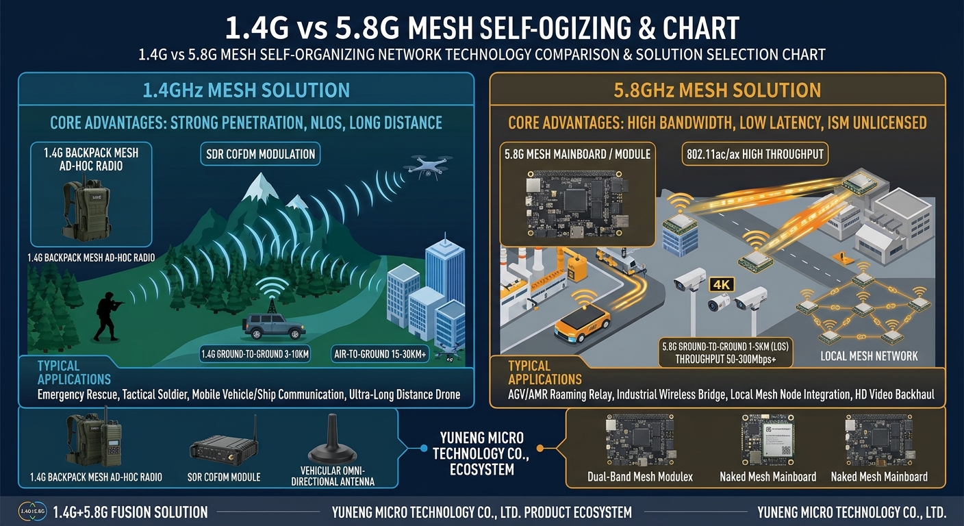
The fundamental difference between the two bands derives from wavelength. At approximately 1.4 GHz the wavelength is about 21 cm; at 5.8 GHz it is about 5 cm. The lower band exhibits materially better diffraction around and penetration through walls, vegetation, and terrain. The higher band permits smaller antennas, a wider usable bandwidth, and easier implementation of higher-order modulation. All engineering differences between the two follow from this relationship.
A terminology clarification is required. “1.4G” is an industry convention rather than a formal band designation. It refers to private-network spectrum in the vicinity of 1.4 GHz. Equipment operates within narrow segments of 1400–1520 MHz, and the specific frequencies vary by model and by project (for example 1400–1480 MHz or 1420–1520 MHz). “5.8G” denotes the 5725–5850 MHz ISM band, the upper portion of the unlicensed 5 GHz Wi-Fi spectrum. One is licensed or project-specific spectrum; the other is unlicensed and open to all users. This distinction accounts for the entirely different equipment ecosystems associated with each.
A second distinction, frequently overlooked, concerns implementation architecture. The majority of 5.8 GHz equipment is based on mature commercial Wi-Fi chipsets from Qualcomm, MediaTek, and other suppliers, which reduces cost and provides a well-established supply chain. No commercial Wi-Fi silicon supports the 1.4 GHz band, so manufacturers generally adopt an FPGA + SDR (software-defined radio) architecture. The rationale is set out in Section 2.2.
| Parameter | 1.4 GHz mesh | 5.8 GHz mesh |
|---|---|---|
| Frequency range | 1400–1520 MHz (private 1.4 GHz spectrum; exact frequencies by model, see Section 8) | 5725–5850 MHz (ISM, unlicensed, upper 5 GHz Wi-Fi band) |
| Physical layer | COFDM with 2×2 MIMO, FPGA + SDR architecture, reconfigurable waveform | Wideband OFDM, high-order modulation (up to 256QAM) |
| Diffraction / penetration | Strong, excellent non-line-of-sight (NLOS) performance | Weak, highly dependent on line of sight (LOS) |
| Single-hop range | 30 km+ vehicle-to-vehicle or fixed-to-fixed with clear line of sight; 50 km+ air-to-ground; 300 m–1 km in obstructed terrain | 10–20 km with elevated antennas and line of sight; hundreds of metres when obstructed |
| Typical throughput | 60–120 Mbps per node (about 70–90 Mbps at 20 MHz, about 120 Mbps at 40 MHz) | 300 Mbps–1 Gbps+ per link |
| Channel bandwidth | 2/5/10/20/40 MHz, configurable | 20/40/80 MHz (Wi-Fi standards) |
| Receiver sensitivity | About -100 dBm (down to -103 dBm in 5 MHz narrowband mode) | Around -90 dBm, varying with bandwidth |
| Per-hop throughput loss (estimate) | 40–60% of throughput retained per hop | 30–50% of throughput retained per hop |
| Mobility | Handles comms-on-the-move well; strong multipath resistance | Needs tuning at high speed; prone to fluctuation |
| Antenna size | Larger (λ ≈ 21 cm) | Small (λ ≈ 5 cm), well suited to airborne use |
| Interference resilience | Dedicated spectrum, intelligent channel selection, AES-128/256 | Crowded with consumer interferers; must avoid Wi-Fi channels |
| Node scale | 32–64 nodes per channel, depending on model | Suited to shallow backbone links, not deep multi-hop chains |
| Typical form factors | Handheld, manpack, vehicle, vessel, UAV relay | Fixed backhaul, airborne video, backbone bridge |
| Can both bands form one mesh? | No. Each radio operates on a single band, and all nodes in a mesh must match. 1.4 GHz and 5.8 GHz networks are always separate. | |
The distances and attenuation figures above are either manufacturer published values or engineering estimates. Actual performance depends materially on antenna gain, mounting height, terrain shielding, noise floor, and traffic profile. Published range figures assume unobstructed line of sight, high-gain antennas, and ideal mounting conditions. In the field, performance typically reaches only 30–60% of the published value. A site survey shall be carried out before any design is submitted for quotation.
2.2 Requirement for an FPGA + SDR architecture at 1.4 GHz
5.8 GHz mesh equipment can leverage the established Wi-Fi ecosystem. 802.11ac/ax chipsets implement OFDM, MIMO, channel coding, and the MAC in silicon, so the manufacturer need only add a routing layer. The 1.4 GHz band (1400–1520 MHz) is neither ISM spectrum nor supported by any commercial Wi-Fi chipset, and a standard Wi-Fi baseband cannot simply be retuned. Accordingly, 1.4 GHz equipment typically adopts the following architecture:
| Layer | Typical implementation | Function |
|---|---|---|
| RF front end | Wideband transceiver, linear PA, cavity or dielectric filters | Transmission, filtering, and power amplification within the 1.4 GHz band (commonly 2×2 W to 2×10 W) |
| Baseband | FPGA (field-programmable gate array) | COFDM modulation and demodulation, channel coding, synchronisation, and MIMO processing. Logic executes in parallel in hardware, giving deterministic latency and precise frame timing control |
| Protocol and waveform | SDR (software-defined radio) | Waveform parameters are configured in software or firmware: channel bandwidth, modulation order, frequency-hopping pattern, and TDMA slot structure may be adjusted on site or customised per project |
| Routing and networking | Embedded processor plus proprietary routing | Runs OLSR-class or proprietary link-state routing for neighbour discovery, multi-hop forwarding, and topology self-healing |
| Services and applications | Linux or embedded OS | PTT voice, video return, GIS positioning, serial passthrough, and 4G/5G public network access |
This architecture provides four capabilities that are difficult to achieve with a 5.8 GHz Wi-Fi design:
- Custom waveform. Voice, telemetry, and video may each be assigned a separate modulation, coding scheme, and frame structure, rather than being constrained by the Wi-Fi frame format.
- Deterministic timing. The frame-timing accuracy provided by parallel FPGA processing is a prerequisite for TDMA slot allocation, multi-hop scheduling, and frequency-hopping synchronisation. Contention-based CSMA/CA access cannot provide equivalent determinism.
- Narrowband sensitivity. In 2 MHz or 5 MHz narrowband mode, sensitivity reaches -103 dBm, trading bandwidth for extended range and improved interference resilience. Wideband Wi-Fi waveforms cannot achieve this.
- Customisable interference resilience and encryption. Hopping patterns, intelligent channel selection, AES-128/256, and integration with external encryption equipment can all be implemented at the baseband layer.
The trade-off is correspondingly clear. FPGA-based designs require a longer development cycle and incur higher power consumption and cost than commercial Wi-Fi silicon; consequently, a 1.4 GHz radio is generally more expensive and physically larger than a 5.8 GHz unit of comparable headline specification. This also explains why 5.8 GHz is appropriate for volume deployment on mature silicon, while 1.4 GHz is appropriate where a customisable waveform is required to address specific environmental conditions.
3. Band selection criteria by operational scenario
3.1 Scenarios for which 1.4 GHz shall be specified
- Urban high-rise, basement, tunnel, and collapsed-structure rescue operations involving severe obstruction
- Wildfire response, slope monitoring, and patrol operations in forest, canyon, and dense timber terrain
- Mixed handheld, manpack, and vehicle teams operating on the move
- Linear or meshed relay chains of eight hops or more
- Combined voice, positioning, telemetry, and one or two 1080p video streams
- Incidents in which mains power, public network coverage, and road access are simultaneously unavailable
3.2 Scenarios for which 5.8 GHz shall be specified
- 4K or multi-stream HD video in open terrain
- Line-of-sight UAV data and video links, and high-speed air-to-ground links
- Point-to-point backbone between a command vehicle and a fixed base station
- Temporary venues, event security, and other short-range, high-bandwidth requirements
- High-point-to-high-point links used in place of optical fibre
3.3 Configurations to be avoided
- Do not specify 5.8 GHz for penetration into buildings. A single load-bearing wall may introduce attenuation in excess of 20 dB, and each additional hop compounds the loss.
- Do not specify 1.4 GHz for multiple 4K streams. The bandwidth ceiling is a hard constraint; compression cannot resolve a concurrency requirement.
- Do not attempt to compensate for multi-hop loss by increasing transmit power. Higher transmit power increases the interference footprint and detection risk without improving throughput, and it degrades the signal-to-noise ratio for all other nodes on the network.
4. Wi-Fi mesh, 802.11s, and MANET: technical distinctions
4.1 Relationship between the three layers
| Layer | Designation | Definition | Is it a “real” mesh? |
|---|---|---|---|
| Product category | Wi-Fi mesh (EasyMesh, vendor mesh, 802.11s products) | Networking products based on Wi-Fi chipsets, with emphasis on coverage and ease of deployment | Depends on the underlying protocol: master-slave EasyMesh does not qualify; 802.11s constitutes a basic ad hoc network |
| Protocol standard | IEEE 802.11s-2011 (HWMP routing) | The standard implementation of multi-hop Wi-Fi, defining neighbour discovery, path selection, and congestion control | Yes, a standardized wireless multi-hop mesh, but constrained by Wi-Fi CSMA/CA channel access |
| Network architecture | MANET (Mobile Ad hoc Network) | Infrastructure-free, self-organising networks with highly dynamic topologies, including subclasses such as FANET and VANET | It constitutes the objective and framework; realisation requires coordinated design across the physical, MAC, and routing layers |
4.2 Summary assessment: the problem each technology addresses
Scope of what 802.11s addresses
Prior to 802.11s, Wi-Fi operated in single-hop mode only: a client associated with an access point, and the access point connected to a switch. Where two devices required interconnection without wired backhaul, the only available options were WDS bridging or vendor-specific point-to-point schemes. Such arrangements became unmanageable beyond a small number of nodes, and loops could not be resolved. The 802.11s standard, published in 2011, addressed four requirements:
- Automatic neighbour discovery. On start-up, nodes identify reachable neighbours through beacon and probe frames. Manual entry of peer IP or MAC addresses is not required, which makes it practicable to bring up dozens of nodes within 20 minutes rather than configuring each individually.
- Automatic path selection. HWMP determines which links are used to reach a given destination. The tree-based component relies on Mesh Portal or Root nodes to establish primary routes in advance; the reactive component operates on the AODV principle, flooding a PREQ on demand and receiving a PREP from the destination before the path is established.
- Self-healing. Following link failure, link-quality metrics identify the failed path, the node initiates a new route discovery, and traffic recovers within seconds. This is the principal distinction between a mesh network and a static repeater chain.
- Standardisation and interoperability. Because the standard builds on the 802.11 physical layer and Wi-Fi chipsets, equipment may reuse established RF front ends, drivers, and supply chains. Cost and time to market are substantially lower than for a bespoke private waveform.
Collectively, these four capabilities exchange software complexity for infrastructure-free multi-hop operation. The principal value of 802.11s is not raw performance but the fact that it converted multi-hop networking from a bespoke engineering project into a commercially procurable capability.
Limitations of 802.11s
802.11s modifies only the networking functions above the MAC layer; the physical layer remains standard Wi-Fi. This choice delivers the cost advantage and simultaneously establishes the performance ceiling:
- Penetration. The waveform remains Wi-Fi OFDM. Operated at 5.8 GHz into a load-bearing wall, a hillside, or dense forest, attenuation is unchanged by the use of 802.11s.
- Multi-hop throughput decay. CSMA/CA is contention-based, so each hop must contend for the channel again. Effective throughput declines sharply with hop count. This is a property of the shared physical layer that no routing protocol can compensate for.
- High mobility. HWMP path maintenance operates on a convergence cycle. With fast-moving vehicle or airborne nodes, a route may fail almost immediately after establishment, manifesting as packet loss and jitter.
- Hard QoS. The standard addresses connectivity only. Voice, control commands, and video compete on the same network without engineering-grade timeslot guarantees.
The positioning of 802.11s is therefore unambiguous: it is a sound connectivity standard, but it is not a solution for guaranteeing service under adverse RF conditions.
Scope of what MANET addresses
MANET proceeds from premises that are both more fundamental and more demanding than those of 802.11s. IETF RFC 2501 specifies them: absence of fixed infrastructure, unrestricted node mobility, continuously changing topology, limited and potentially asymmetric link bandwidth, and endpoints constrained by battery capacity and processing power. Maintaining an operational network under these conditions requires four questions to be addressed concurrently, and the MANET framework is structured around precisely these four:
- How are paths computed under a changing topology? This yields proactive routing (OLSR maintains network-wide topology, converging rapidly with stable overhead) and reactive routing (AODV and DSR establish routes on demand, with lower overhead but higher latency), together with engineering variants that select routes by link state or traffic class.
- How is link quality assessed? Reachability alone is insufficient. RSSI, SNR, ETX, latency, and packet loss shall be incorporated into the routing metric; otherwise the computed shortest path may be a link that is about to fail.
- What occurs when a node is lost? The network shall reorganise autonomously, and the loss of any single node shall not cause network-wide failure. This is the engineering definition of survivability and is the first characteristic to verify in any emergency-response procurement.
- How do multiple traffic classes coexist? Voice, video, control, and positioning have fundamentally different bandwidth and latency requirements, which requires differentiated treatment at the MAC and routing layers.
It should also be noted that MANET is a design framework rather than a protocol implementation. It specifies what shall be considered, not which physical-layer waveform or routing protocol shall be used. Two products may both claim conformance to MANET principles and differ materially in performance. This is precisely why physical-layer and routing-layer implementation details shall be examined during evaluation.
Application to the band selection question
| Technology | Addressed requirements | Unaddressed requirements | Relationship to band | Applicability in the scenarios of this document |
|---|---|---|---|---|
| 802.11s | Provides Wi-Fi devices with standardized infrastructure-free multi-hop capability: discovery, path selection, self-healing, and interoperability, at minimum cost and shortest time to market | Penetration through severe obstruction, multi-hop throughput decay, high-dynamic topology, hard QoS | The physical layer is fixed as Wi-Fi and is therefore inherently tied to 5.8 GHz and 2.4 GHz; its strengths and limitations are those of those bands | Campus, warehouse, port yard, and temporary security deployments: moderate scale, predominantly static nodes, line of sight or partial obstruction |
| MANET | Maintains an operational network without infrastructure, under rapid topology change and limited bandwidth: route convergence, link metrics, survivability, and traffic prioritisation | Specifies neither a physical-layer waveform nor a particular protocol; the framework alone guarantees no performance, and results depend entirely on implementation | Band-agnostic, but requires a customisable physical layer, consistent with 1.4 GHz using an FPGA/SDR reconfigurable waveform | Firefighting, wildfire, vehicle convoys, and UAV swarms: severe obstruction, high mobility, multiple hops, mixed traffic |
The two assessments can be restated in relation to the principal findings of this document:
- 802.11s and 5.8 GHz are technically linked. 802.11s is a multi-hop protocol operating on the Wi-Fi physical layer, and 5.8 GHz is a Wi-Fi band; its advantages (cost, throughput, interoperability) and limitations (penetration, mobility, multi-hop decay) are therefore those of 5.8 GHz. Specification of 802.11s entails acceptance of all physical constraints associated with 5.8 GHz.
- MANET constitutes the evaluation criterion; 1.4 GHz is one implementation route. MANET requires a physical layer adaptable to high mobility and severe obstruction: adjustable bandwidth, interchangeable waveforms, and controllable timeslots. Standard Wi-Fi silicon cannot provide these capabilities. Only an FPGA + SDR architecture of the type used at 1.4 GHz (see Section 2.2) affords this flexibility.
The evaluation sequence should accordingly be: first apply the MANET requirement set to establish whether the network can remain operational under extreme conditions; then apply the cost rationale of 802.11s to establish whether the particular site justifies the additional expenditure. For the majority of campus and warehouse projects, the second assessment concludes that it does not, and 802.11s is sufficient. For firefighting, wildfire, and convoy operations, operational survival is mandatory; the physical-layer ceiling of 802.11s then becomes a binding constraint, and a 1.4 GHz private mesh is the appropriate solution. The following two sections set out the supporting technical basis for both assessments.
4.3 Capabilities and limitations of 802.11s
The preceding section stated the assessment; this section sets out the technical basis, beginning with the mechanics of HWMP and then identifying why they degrade under multi-hop, mobility, and obstruction.
802.11s is the Wi-Fi mesh standard published by IEEE in 2011. Its core is HWMP (Hybrid Wireless Mesh Protocol), which combines proactive tree-based routing anchored on Mesh Portal or Root nodes with on-demand AODV-style reactive routing. It provides discovery, link formation, and re-routing following failure, and may properly be described as a standardized ad hoc mesh.
In operational deployments, however, 802.11s is subject to several constraints:
| Constraint | Technical cause | Operational consequence |
|---|---|---|
| Rapid throughput decay with hop count | CSMA/CA shares a half-duplex channel, so each hop must contend again; contention increases with the number of nodes sharing the channel | Measured effective throughput frequently falls below one quarter of the single-hop rate after 3–5 hops (varying with bandwidth, node count, and offered load), rendering video services effectively unusable |
| Topology instability | HWMP path maintenance relies on periodic PREQ/PREP/PANN frames and link metrics such as the Airtime Link Metric | With fast-moving vehicle or UAV nodes, routes fail repeatedly, producing packet loss and jitter |
| Limited penetration | The physical layer remains Wi-Fi OFDM, and 2.4 GHz and 5 GHz attenuate rapidly through buildings and forest | Multi-storey interiors and ridge back-slopes require dense node deployment |
| Absence of traffic prioritisation | The standard addresses connectivity only; hard QoS for video, voice, and control requires support from higher layers | Under concurrent traffic, control commands are displaced by video traffic |
| Scale limitation | Routing overhead scales with node count; measured Wi-Fi multi-hop networks show slower convergence beyond several dozen nodes | Suitable for deployments of several dozen nodes; larger networks require partitioning |
Conclusion: 802.11s is applicable to networks of moderate scale with low to moderate mobility and line-of-sight or partially obstructed conditions — campus, warehouse, temporary security deployment, and port yard environments. Where terrain obstruction is severe, nodes are highly mobile, or linear relay chains in excess of eight hops are required, 802.11s alone will not meet the requirement.
4.4 Definition of MANET and its broader scope relative to 802.11s
The preceding section established the mechanics and the performance ceiling of 802.11s. This section explains why MANET requires an additional layer of abstraction above it, and what that layer constitutes in engineering terms.
MANET is not a specific protocol standard but a category of network, first defined systematically by the IETF MANET working group in RFC 2501: a set of mobile nodes that self-organise into a temporary network without reliance on any fixed infrastructure, in which each node functions as both endpoint and router. Routing protocols derived from MANET principles include OLSR (RFC 3626 and its successor OLSRv2, RFC 7181), AODV (RFC 3561), DSR, and DSDV. Derived network classes include VANET (vehicular), FANET (UAV), and WSN (sensor networks).
The distinction is as follows: 802.11s is one specific implementation of “Wi-Fi physical layer plus a mesh routing protocol”; MANET is a design framework of “any physical layer, any ad hoc routing protocol, highly dynamic topology.” 802.11s may therefore be regarded as one subset implementation of MANET. It provides decentralised self-organisation, but its physical layer is fixed to Wi-Fi, and its link metrics and QoS capabilities are comparatively limited.
Broadband private mesh equipment, such as the Ynwmicro Wi-Fi mesh range covering manpack, vehicle comms-on-the-move, airborne, handheld NLOS, and portable command platforms, generally combines the following elements:
- Physical layer: a dedicated COFDM/OFDM waveform that can operate in the 1.4 GHz, 2.4 GHz, and 5.8 GHz bands, with NLOS capability and multipath resistance
- MAC layer: a modified hybrid TDMA/CSMA access scheme that reserves slots for voice and control traffic and reduces multi-hop congestion
- Routing layer: OLSR-class proactive routing or proprietary link-state routing, selecting paths using link quality (RSSI/SNR/ETX) and traffic type
- Application layer: built-in PTT voice, video return, GIS positioning, serial passthrough, and other private-network services
In engineering terms, this combination is substantially closer to the design objectives of MANET than equipment that merely provides multi-hop Wi-Fi capability.
4.5 Comparative matrix of the four network types
| Parameter | Master-slave Wi-Fi mesh (EasyMesh / consumer mesh) |
802.11s mesh | MANET framework (including VANET / FANET) |
Broadband private mesh (1.4 GHz / 5.8 GHz equipment) |
|---|---|---|---|---|
| Topology | Predominantly star, with a master node at the root | Mesh, with optional Root/Portal | Fully peer-to-peer | Fully peer-to-peer, with optional hierarchy |
| Central node | Yes (controller or master) | No (optional root) | No | No |
| Routing | Proprietary, generally static backhaul | HWMP | OLSR / AODV / DSR / proprietary | OLSR-class, with link quality and traffic awareness |
| Mobility support | Limited (nodes essentially fixed) | Moderate (low speed) | High (highly dynamic) | High (vehicle, airborne, dismounted) |
| Multi-hop depth | 1–2 hops | 3–6 hops (throughput-limited) | Theoretically unlimited; in practice protocol-dependent | 8–15 hops (linear and meshed, subject to traffic profile) |
| Physical layer | Wi-Fi 2.4/5/6 GHz | Wi-Fi 2.4/5 GHz (802.11s builds on 802.11a/b/g/n/ac) | Unconstrained (Wi-Fi, private radio, satellite) | COFDM/OFDM at 1.4/2.4/5.8 GHz |
| NLOS capability | Limited | Limited to moderate | Dependent on the physical layer | High at 1.4 GHz, limited at 5.8 GHz |
| Typical throughput | Hundreds of Mbps to Gbps (single hop) | Tens to hundreds of Mbps (single hop) | Wide range | 60 Mbps–1 Gbps, by band |
| Healing time | Seconds to tens of seconds | Hundreds of milliseconds to seconds | Milliseconds to seconds (protocol-dependent) | Under one second |
| Typical application | Whole-premises coverage, small offices | Warehouse AGVs, campus backhaul, ports | Defence, connected vehicles, UAV swarms, emergency response | Fire and rescue, wildfire, border and coastal defence, vehicle convoys, UAV video |
| Cost category | Low | Low to moderate | High (military grade) | Moderate (commercial private network) |
4.6 Selection guidance
- Residential or office coverage: master-slave Wi-Fi mesh is sufficient. Additional expenditure on ad hoc networking capability is not justified.
- Warehouse, campus, or yard deployments at small scale with predominantly static nodes: 802.11s or a commercial mesh product based on it offers the most favourable cost-benefit ratio.
- Defence applications, academic VANET research, and UAV swarm algorithm validation: the MANET framework applies, with emphasis on routing protocols and simulation.
- Firefighting, emergency response, wildfire, border and coastal defence, and vehicle convoy operations in which power, network, and road access may all be unavailable: broadband private mesh equipment shall be specified. It implements MANET self-organising principles in commercially procurable, field-deployable hardware.
5. Prohibition on mixed-band meshing
5.1 Technical basis for the prohibition
| Layer | Technical basis |
|---|---|
| RF hardware | The RF front end, filters, power amplifier, and antennas of a given radio are designed for a single band. The centre frequencies of 1.4 GHz and 5.8 GHz differ by approximately a factor of four (about 1.46 GHz versus 5.79 GHz), so a single RF chain cannot serve both |
| Physical-layer waveform | 1.4 GHz generally uses narrowband COFDM; 5.8 GHz uses wideband OFDM with high-order modulation. Frame structure, preambles, and modulation and coding sets differ, and the two cannot demodulate each other |
| Neighbour discovery | Meshing depends on periodic beacon or HELLO frames for neighbour discovery. On different bands, neither side receives the other’s beacons, the neighbour table remains empty, and no routes can be established |
| Routing domain | A routing protocol requires consistent link metrics and a shared topology database. Nodes on different bands have no usable link between them and cannot join the same routing domain |
| Channel planning | 1.4 GHz private frequencies and 5.8 GHz channels are entirely separate systems; channel numbering, bandwidth, and power limits are not interchangeable |
Where a supplier claims “single-device dual-band mesh with automatic 1.4 GHz and 5.8 GHz interoperability,” the following points shall be clarified: whether the implementation comprises two RF modules bridged at the application layer, or two independent networks interconnected at the service layer. In most cases the former is two radios housed in a single enclosure and the latter is two separate networks operating in parallel.
5.2 Permitted approach: selection by site, area, or operational phase
Since the two bands are mutually exclusive within a network, the selection procedure is as follows: establish whether coverage or bandwidth is the governing deficiency for the area or phase in question; specify 1.4 GHz where coverage is deficient and 5.8 GHz where bandwidth is deficient.
| Site conditions | Band to be specified | Basis |
|---|---|---|
| Building interiors, basements, tunnels, dense forest, canyons | 1.4 GHz | NLOS propagation is the governing constraint, and bandwidth demand does not exceed 1080p |
| Open terrain, high point to high point, UAV line-of-sight links | 5.8 GHz | Line of sight is assured, and 4K, multiple video streams, or large file transfer is required |
| A single operation progressing from building interior to open terrain | Separate networks per area | Transfer to the 5.8 GHz network on reaching open terrain; bands shall not be mixed |
| Long-term fixed backhaul backbone | 5.8 GHz | Fixed positions, assured line of sight, high bandwidth demand |
| Mobile teams operating under heavy obstruction | 1.4 GHz | Comms-on-the-move performance and multipath resistance take precedence over peak bandwidth |
5.3 Permitted coexistence of both bands
Where a project genuinely requires both bands (for example, a 5.8 GHz backbone along a ridge with 1.4 GHz access in the forest below), the design shall comprise two independent mesh networks, each self-healing and infrastructure-free, interconnected at a service gateway or Layer 3 router on the command vehicle. A 1.4 GHz node shall not connect directly to a 5.8 GHz node.
        [1.4 GHz mesh]                          [5.8 GHz mesh]
        Handheld <-> Manpack <-> Vehicle        High point A <-> High point B <-> Base station
              ^                                              ^
              +----------- separate networks ----------------+
                                   ^
                     No wireless hop across the two bands.
                     Interconnection occurs only at the gateway.
                                   ^
                   [Command centre / satellite / 5G uplink]
5.4 Statement of the rule
One site, one network; one band, one equipment set. Specify 1.4 GHz for coverage and 5.8 GHz for bandwidth. Where both must coexist, interconnect them at a gateway; a cross-band hop is not permitted.
6. Traffic capacity and bandwidth budget (engineering estimates)
| Traffic type | 1.4 GHz | 5.8 GHz |
|---|---|---|
| Voice (PTT) | Primary | Rarely used |
| BeiDou / GPS positioning | Primary | Not used |
| Telemetry / serial passthrough | Primary | Not used |
| 1–4 streams of 1080p video | Supported | More stable |
| 4K or multiple video streams | Marginal | Primary |
| File transfer | Secondary | Primary |
| Vehicles on the move | Primary | Supplementary where line of sight exists |
Per-hop retention values for planning purposes (to be confirmed by test):
- 1.4 GHz retains 40–60% of throughput per hop
- 5.8 GHz retains 30–50% of throughput per hop
- Video traffic shall be confined to two hops wherever practicable
A worked example demonstrates the constraint. A handheld 1.4 GHz terminal transmitting a 4 Mbps 1080p stream over four hops, at an assumed 50% retention per hop, leaves an effective link budget of approximately 0.25 Mbps, which is insufficient for usable video. Video quality is highly sensitive to hop count; sites with HD video requirements are therefore generally better served by a 5.8 GHz network offering high single-hop bandwidth over few hops than by routing video through a 1.4 GHz mesh.
7. Reference deployment profiles
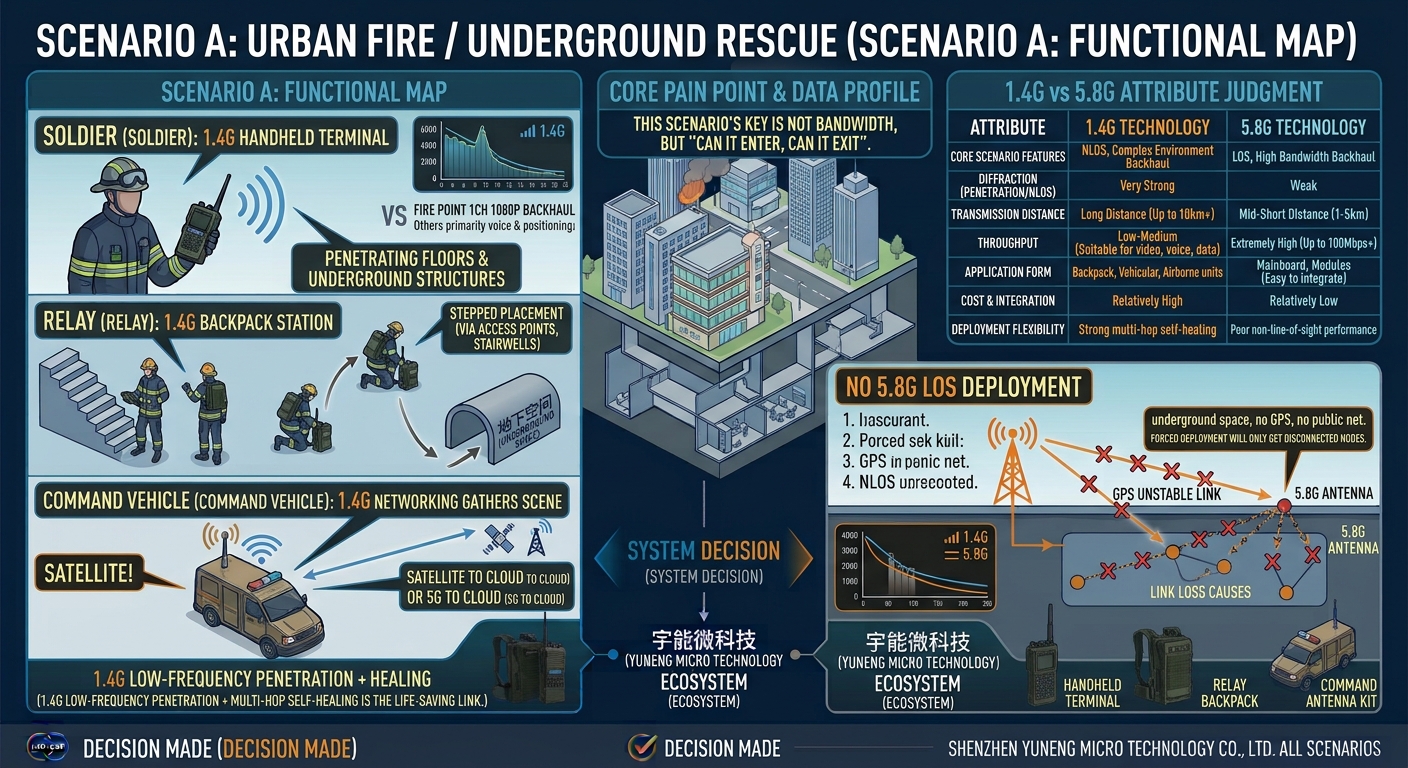
Scenario A: urban fire and subterranean rescue
- Dismounted crews: 1.4 GHz handhelds capable of penetrating floors and underground structures
- Relays: 1.4 GHz manpack radios staged progressively in stairwells and at entry points
- Command vehicle: aggregates the 1.4 GHz mesh on site and backhauls by satellite or 5G
- Video: one 1080p stream from the fire floor to the forward command post; all other traffic comprises voice and positioning data
The governing requirement in this scenario is ingress and egress, not bandwidth. Underground there is no GPS and no commercial network coverage, so the low-band penetration and multi-hop self-healing of 1.4 GHz constitute the primary lifeline. This environment offers no line of sight for 5.8 GHz, and specifying 5.8 GHz would leave nodes unable to establish links.
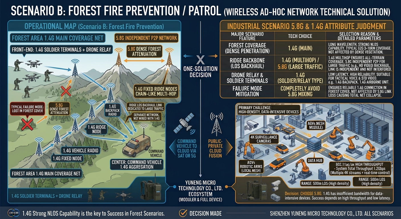
Scenario B: wildfire response and patrol
- Field teams: 1.4 GHz handhelds with UAV relays
- Ridges: fixed 1.4 GHz nodes in a multi-hop chain that routes around vegetation and terrain
- Command: a command vehicle aggregates the 1.4 GHz mesh and uplinks by satellite or 5G
The characteristic failure mode in forest terrain is a summit point-to-point bridge that becomes unavailable as soon as crews descend into the tree canopy. Vegetation attenuates heavily and 5.8 GHz is close to unusable in dense forest; the coverage network shall therefore be based on 1.4 GHz. Where a fixed ridge-line line-of-sight backhaul is also available, it may be configured as a separate 5.8 GHz point-to-point network dedicated to bulk traffic. It remains a separate network and shall not be mixed with the 1.4 GHz forest network.
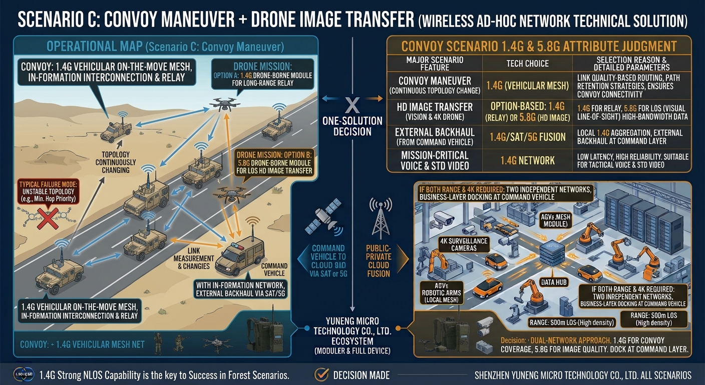
Scenario C: vehicle convoy with UAV video
- Convoy: 1.4 GHz vehicle mesh operating on the move, with all vehicles relaying for one another on the same frequency
- UAV: selected per mission — a 1.4 GHz airborne module for long-range relay, or a 5.8 GHz airborne module for line-of-sight HD video
- Command vehicle: shares the convoy frequency and backhauls by satellite or 5G
The principal difficulty in a convoy is continuous topology change. Vehicle spacing ranges from tens of metres to several kilometres, and the set of available links changes every second. Routing shall therefore be configured to damp transient fluctuation and shall not recompute the entire network in response to brief link variation. This is why private mesh equipment relies on link-quality metrics and path retention strategies rather than a simple minimum-hop rule.
Where a single mission requires both long-range convoy communications and 4K video, a single radio operating on two bands is not an acceptable solution. Two separate networks shall be configured: 1.4 GHz for the convoy to assure connectivity on the move, and 5.8 GHz for UAV video to assure image quality. The two networks shall be interconnected at the service layer on the command vehicle.
8. Equipment form factors and evaluation criteria
Every radio in a given design operates on a single band. The specifications below are taken from the published figures for the zukaka 1.4 GHz product line and may serve as a basis for a tender schedule or configuration sheet.
| Node type | Reference model | Band / waveform | Key published specifications |
|---|---|---|---|
| Handheld | Handheld mesh radio | 1420–1520 MHz / COFDM 2T2R | 90 Mbps at 20 MHz; 2×2 W; sensitivity ≤ -100 dBm; 32+ nodes; IP66; approximately 1.2 kg; approximately 6 h battery life |
| Manpack relay | Manpack mesh radio | 1420–1520 MHz / MIMO 2×2 | 120 Mbps at 40 MHz; 2×33 dBm; sensitivity -103 dBm at 5 MHz; 64 nodes per frequency; IP67; 4 kg; 25.2 V / 10.5 Ah (approximately 6 h; 8–12 h with extended battery) |
| Vehicle (comms on the move) | Vehicle mesh radio | 1420–1520 MHz / COFDM 2T2R | 90 Mbps at 20 MHz; 2×10 W; sensitivity ≤ -100 dBm; 32+ nodes per frequency; 30 km+ with clear line of sight, 50 km+ air to ground; IP65; 1U rack mount |
| Airborne module | Airborne mesh module | 1400–1480 MHz / COFDM | 70 Mbps peak at 20 MHz; 2–4 W adjustable transmit power; up to 64 nodes; 10 km+ air to ground, 300–1000 m when obstructed; approximately 1.1 kg including battery |
| Portable command platform | Portable command and dispatch platform | 1400–1500 MHz / COFDM 2T2R | 70 Mbps at 20 MHz; 33 dBm; sensitivity -96 dBm at 2 MHz; 32 nodes (expandable to 64); 15.6-inch rugged i7 case; IP65; approximately 13.8 kg |
| Fixed base station / backbone | 5.8 GHz bridge or private base station | 5725–5850 MHz / OFDM | 300 Mbps–1 Gbps class; high-gain directional antenna; 10–20 km line of sight |
For selection purposes, reference may be made to the Ynwmicro Wi-Fi mesh product range, which covers manpack, vehicle comms-on-the-move, airborne, handheld NLOS, and portable command platforms. All units use an FPGA + SDR architecture with a COFDM multi-carrier waveform, support infrastructure-free meshing, and accommodate point-to-point, linear, and meshed topologies. They are designed for environments without infrastructure: emergency response, mobile vehicle and vessel communications, UAV coordination, and remote-area surveillance.
Suppliers shall be evaluated against the following five criteria:
- Genuine infrastructure independence. Removal of any node shall result in network re-convergence rather than loss of overall connectivity.
- Measured multi-hop performance. Throughput and latency curves measured at five hops or more shall be provided; single-hop peak figures are not acceptable evidence.
- Baseband architecture. The supplier shall state whether the unit uses an FPGA + SDR with a customisable waveform or a general-purpose SoC with a fixed waveform.
- Traffic QoS. Evidence shall be provided that voice and control traffic are protected under concurrent multi-service load.
- Field delivery capability. The supplier shall confirm provision of site surveys, node placement planning, and commissioning support.
9. Deployment requirements and prohibited practices
Governing requirements: survey first, then position nodes. One network, one band; mixing is prohibited. Coverage requires 1.4 GHz; bandwidth requires 5.8 GHz. Radio links shall be established and verified before any cloud or upper-layer integration is undertaken.
- Transmit power shall not be increased without analysis. Power determines whether the far end can receive; it does not reduce channel occupancy.
- Two bands shall not be configured on one network. 1.4 GHz and 5.8 GHz have incompatible physical layers, and mixing them results in two disconnected islands.
- Traffic shall be prioritised across hops. Within a network, voice and positioning shall take precedence over video so that control commands are never displaced.
- Redundancy shall be provided for critical nodes. Spare or cloned nodes shall be pre-staged so that no single unit becomes a bottleneck for the whole network.
- Antenna placement shall be treated as a design parameter of higher priority than equipment model. Two identical 5.8 GHz radios mounted at 3 m and at 30 m will differ in performance by a margin greater than the price difference between models.
10. Frequently asked questions
Is a mesh network the same thing as 802.11s?
No. 802.11s is an IEEE standard for multi-hop Wi-Fi mesh and constitutes one specific implementation of a mesh network. The term mesh network denotes a broader engineering concept whose physical layer may be Wi-Fi or a dedicated COFDM waveform. Many commercial broadband mesh systems do not conform to 802.11s; they use proprietary link-state routing and a dedicated physical layer to obtain improved NLOS and multi-hop performance.
What is the difference between MANET and a mesh network?
MANET (mobile ad hoc network) is the research and engineering term for a class of networks defined in IETF RFC 2501, characterised by highly mobile nodes, absence of infrastructure, and multi-hop self-organisation. Mesh describes the shape of the topology, namely nodes interconnected in a mesh. The two concepts overlap substantially and are used interchangeably in general usage. Strictly, MANET emphasises mobility and routing protocol design, whereas mesh emphasises topology and interconnection. VANET (vehicular) and FANET (UAV) networks are both branches of MANET.
Can 1.4 GHz and 5.8 GHz nodes form a single mesh?
No. A mesh radio operates on one band at any given time, and all nodes in a network must share the same frequency, bandwidth, and waveform parameters in order to discover neighbours and participate in routing. The centre frequencies differ by approximately a factor of four, and the RF chains, physical-layer waveforms, and channel plans are not interchangeable, so no link can be established across bands. The required approach is to select one band per site, area, or phase. Where both bands are genuinely required, two independent networks shall be operated and interconnected at the service layer through a gateway.
Can a single device house both a 1.4 GHz and a 5.8 GHz module?
Such a unit may be built as a dual-radio device, effectively two radios in one enclosure, but it does not constitute a single dual-band mesh. Each radio forms its own mesh plane, and the unit forwards traffic internally between them. Wireless cross-band neighbour relationships do not exist. In procurement, a dual-radio device shall be distinguished from a genuinely converged dual-band network; the two are not equivalent.
What is the required configuration where a site has both heavily obstructed areas and a 4K video requirement?
Two networks shall be configured. 1.4 GHz provides connectivity in the obstructed areas, and a separate 5.8 GHz network carries HD video where line of sight exists. The two shall be interconnected at a service gateway on the command vehicle or at the forward command post. Two conflicting requirements shall not be resolved by means of a single network, and 1.4 GHz nodes shall not be forced into a 5.8 GHz network.
How many hops can a mesh network support?
No single figure applies; the answer depends on the physical layer, channel bandwidth, traffic type, and routing protocol. In practice, a 1.4 GHz broadband mesh in a linear deployment can support 8–15 hops, with throughput and latency degrading measurably at each additional hop. Acceptance shall be judged on whether the traffic remains usable rather than on whether nodes remain connected.
Why do published distances not hold up in the field?
Vendor distances are generally single-hop test results obtained under ideal line of sight with high-gain antennas and no interference. Real sites exhibit vegetation loss, terrain masking, co-channel interference, and insufficient antenna height, and actual range is often 30–60% of the published figure. This document therefore reiterates the same requirement: survey first, then position nodes.
Does a mesh network require a fixed base station?
No. The defining characteristic of an infrastructure-free mesh is that nodes are peers. Where any node becomes unavailable, the network routes around it, so there is no single point of failure in which the loss of a base station disables the entire network. A command vehicle or fixed base station provides only an external gateway and aggregation point; it is not required for continued network operation.
Will a 5.8 GHz mesh interfere with Wi-Fi at the site?
It may. 5.8 GHz shares the 5725–5850 MHz ISM band with consumer Wi-Fi, and interference becomes pronounced in dense Wi-Fi environments such as large events. Sub-channels away from congested channels may be selected, directional antennas may be used to improve signal-to-noise ratio, or 1.4 GHz private spectrum may be adopted in high-interference areas. Equipment shall be confirmed at procurement to support spectrum scanning and automatic channel avoidance.
Require assistance in specifying a mesh design for a project?
Where a mesh network is to be specified for fire and rescue, wildfire response, border and coastal defence, vehicle convoys, or UAV video, the following site information shall be provided: terrain, obstruction, node count, traffic bandwidth, mobility, and power availability. A recommended band, node count, and node placement will be issued based on the Ynwmicro Wi-Fi mesh range.