Power Tunnel Mesh Network Solution: Self-organizing Wireless Communication for Inspection Robots and Personnel
Key Overview
This article is for: Power infrastructure engineers, tunnel construction managers, industrial IoT solution architects, and equipment procurement teams evaluating wireless communication solutions for underground power tunnel projects.
Core Issue: Concrete power tunnels present extreme wireless propagation challenges—narrow enclosed spaces, metal bracket obstructions, and construction materials block signals. Standard WiFi and AGV wireless bridge boards cannot meet multi-hop mesh requirements for reliable robot video backhaul and remote control.
Key Conclusions: Mesh self-organizing networks (MANET) are the only viable architecture for power tunnel wireless communication. Zukaka’s 2.4GHz Mesh motherboards (YN300A/YN300C) provide NLOS transmission capability, 10+ hop relay, and mobile node support—critical for 500m and 1km tunnel deployments. AGV wireless bridge boards are unsuitable due to limited multi-hop capability and WiFi-centric design.
Project Scenario Overview
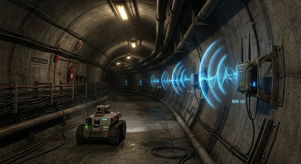
Concrete power tunnels during construction present unique challenges for wireless communication. These narrow, enclosed spaces contain metal reinforcing bars, construction scaffolding, and various materials that create signal dead zones and severe attenuation. The network must support multiple critical applications simultaneously.
Business Requirements
- HD Video Backhaul: Inspection robots transmit real-time HD video (1080p/30fps) for remote monitoring of tunnel conditions
- Gas Monitoring Data: Sensor nodes send methane, CO, and oxygen level readings for safety compliance
- Positioning Tracking: Real-time location data for both robots and personnel entering the tunnel
- Remote Control Commands: Low-latency bidirectional communication for robot navigation and operation
Two Deployment Scenarios
| Parameter | 500m Tunnel | 1km Tunnel |
|---|---|---|
| Fixed Base Stations | 3 units (1 portal + 2 relays) | 5 units (1 portal + 4 relays) |
| Mobile Nodes | 1 unit (on robot) | 1 unit (on robot) |
| Maximum Hops | 3 hops | 5 hops |
| Estimated Node Spacing | ~167m | ~200m |
Mesh Network Architecture Design
Traditional WiFi networks rely on a star topology where every AP needs a wired connection back to a central switch. In a power tunnel during construction, running cables is impractical and dangerous. Mesh networks solve this by having each node forward traffic to the next, creating a daisy-chain of wireless backhaul. The linear topology is optimal for tunnels because it follows the natural axis of the environment, minimizing signal path length and interference.
Linear Mesh Topology — Node Roles & Functions
The recommended topology for power tunnels is a linear mesh chain with three distinct node types:
- Portal Node: Located at the tunnel entrance, connects to the ground control center via fiber or Ethernet. Acts as the network gateway, aggregating all tunnel traffic and forwarding to the control center. Must have dual connectivity (mesh + wired) and UPS backup.
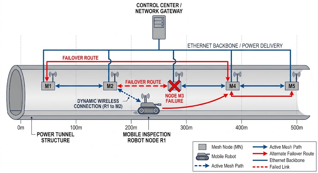
- Relay Nodes: Deployed along the tunnel at 150-200m intervals, each node relays traffic to/from adjacent nodes. Each relay node maintains at least two mesh links (forward and backward), creating redundant paths for self-healing.
- Mobile Node: Mounted on the inspection robot, dynamically connects to the nearest fixed node. Uses MANET mode to maintain connections while moving, with simultaneous links to 2-3 nearest nodes for seamless handoff.
Routing Protocol Selection — AODV vs OLSR vs HWMP
Mesh network performance depends heavily on routing protocol selection. For power tunnel deployments, AODV (Ad Hoc On-Demand Distance Vector) is the optimal choice due to its on-demand nature and low overhead in linear topologies.
| Protocol | Route Discovery | Overhead | Convergence Time | Scalability | Best For |
|---|---|---|---|---|---|
| AODV | On-demand (route request/reply) | Low (only when needed) | 50-100ms | 50+ nodes | Tunnel mesh, mobile nodes, dynamic topology |
| OLSR | Proactive (periodic updates) | High (constant overhead) | 10-50ms | 30-50 nodes | Static networks, high mobility |
| HWMP (802.11s) | Hybrid (on-demand + proactive) | Medium | 100-200ms | 100+ nodes | WiFi-based mesh, large deployments |
Why AODV for Power Tunnels: In a linear topology with predictable node movement, AODV’s on-demand route discovery minimizes control overhead. The protocol establishes routes only when needed, reducing bandwidth consumption that would otherwise be used for periodic OLSR hello messages. YN300A/YN300C implement AODV with route caching and early route expiry to handle dynamic robot movement.
Bandwidth Capacity Planning
Before deployment, calculate total bandwidth requirements to ensure the mesh network can handle all concurrent applications. The formula for required throughput is: Total Throughput = Σ(Application Bandwidth × Redundancy Factor)
Application Bandwidth Requirements
| Application | Required Bandwidth | Direction | Redundancy Factor | Effective Requirement |
|---|---|---|---|---|
| HD Video (1080p/30fps) | 8-12Mbps | Upstream | 1.5x (QoS headroom) | 12-18Mbps |
| Gas Sensor Data (10 sensors) | 50Kbps | Upstream | 1.2x | 60Kbps |
| Positioning (robot + personnel) | 100Kbps | Upstream | 1.2x | 120Kbps |
| Remote Control Commands | 200Kbps | Downstream | 1.5x (low-latency priority) | 300Kbps |
| Total (per tunnel) | ~10Mbps | Both | — | ~15Mbps |
Capacity Verification: Based on the throughput degradation model (Throughput_n = Throughput_0 × (0.5-0.6)^n), at 5 hops (1km tunnel), available throughput is 20-35Mbps. This exceeds the 15Mbps effective requirement, confirming the design has sufficient capacity.
Frequency Selection & Channel Planning
In tunnel environments, channel planning is critical to minimize co-channel interference. The waveguide effect amplifies interference, so careful channel selection is essential.
| Frequency Band | Propagation Model | Available Channels | Maximum Throughput | Link Margin @ 200m | Recommended Use |
|---|---|---|---|---|---|
| 2.4GHz | Tunnel waveguide | 3 non-overlapping (1,6,11) | 150-180Mbps (HT40) | 33dB | Primary mesh backbone |
| 5GHz | Line-of-sight only | 24 non-overlapping | 800-1000Mbps | 13dB | Portal-to-ground (if LOS) |
| Sub-GHz (868/915MHz) | Waveguide, very long range | 1-2 channels | <1Mbps | 50+ dB | Low-bandwidth sensors, emergency |
Channel Reuse Strategy
In a linear mesh chain, channel reuse is limited due to the waveguide effect. The recommended approach is:
- All mesh nodes on same channel: Simplifies routing and allows any node to communicate with any other node directly
- Use HT40 channel bonding: Doubles bandwidth from 72Mbps to 150-180Mbps
- Enable RTS/CTS: Prevents hidden node problem in dense deployments
- Transmit power control: Reduce TX power on relay nodes to minimize interference with distant nodes
Network Redundancy & Self-Healing Mechanism
Mesh networks provide inherent redundancy through multi-path routing. If any node fails, traffic automatically reroutes through alternative paths. YN300A implements a hybrid self-healing mechanism combining proactive monitoring with reactive recovery.
Self-Healing Process
- Link Monitoring: Each node continuously monitors neighbor links via periodic hello messages (100ms interval)
- Failure Detection: Link failure is detected after 3 consecutive missed hello messages (300ms)
- Route Repair: AODV initiates route discovery to find alternative path
- Traffic Rerouting: New route is established and traffic resumes (sub-1-second total)
- Route Optimization: Periodic route discovery finds optimal path once network stabilizes
Failure Scenarios: In a linear topology, a single node failure isolates the downstream segment. To mitigate this, implement redundant node pairs every 300-400m, where two nodes are deployed close together (20-30m apart) with overlapping coverage. This ensures at least one path remains available if either node fails.
Key Technical Challenges & Engineering Solutions
Challenge 1: Signal Attenuation in Concrete — Link Budget Analysis
Concrete walls absorb RF energy significantly. The attenuation follows the formula: Attenuation = (5-10dB/m) × wall_thickness. For a typical 30cm thick concrete wall with steel reinforcement, 2.4GHz signals experience 15-30dB loss, while 5GHz signals lose 25-40dB. Combined with free-space path loss (FSPL), this creates a severe link budget deficit.
Link Budget Calculation for 200m Tunnel Segment
| Parameter | Value | Units |
|---|---|---|
| Transmit Power (YN300A) | 30 | dBm |
| Tx Antenna Gain | 5 | dBi |
| EIRP (Effective Isotropic Radiated Power) | 35 | dBm |
| FSPL @ 200m, 2.4GHz | -84 | dB |
| Concrete Absorption (30cm) | -15 | dB |
| Miscellaneous Loss (cable, connectors) | -3 | dB |
| Rx Antenna Gain | 5 | dBi |
| Received Signal Strength | -62 | dBm |
| Receiver Sensitivity (YN300A) | -95 | dBm |
| Link Margin | 33 | dB |
Solution: The YN300A’s 30dBm (1W) transmit power combined with 5dBi high-gain antennas provides 33dB link margin at 200m spacing—sufficient for reliable communication even with construction materials and metal obstructions. 5GHz would yield only 13dB margin, making it unsuitable for tunnel deployment.
Challenge 2: Non-Line-of-Sight (NLOS) Propagation — Tunnel Waveguide Effect
Tunnel curves, construction materials, and equipment create obstacles that block direct signal paths. In tunnels, RF propagation follows a waveguide mode rather than free-space propagation. The tunnel acts as a rectangular waveguide, supporting multiple propagation modes (TE, TM, TEM) that bounce off walls.
Fresnel Zone Analysis for Tunnel NLOS
The first Fresnel zone radius at 200m with 2.4GHz is approximately 1.8 meters. In a typical 4m × 4m tunnel cross-section, this means the signal path must clear obstacles within 1.8m of the center line. When line-of-sight is blocked, the waveguide effect allows signals to propagate via wall reflections.
Solution: YN300A supports adaptive MIMO with spatial diversity, leveraging multiple reflected paths simultaneously. The antenna array processes signals arriving from different angles (direct + reflected), maintaining reliable links even around 90° tunnel curves with up to 50m radius. This is critical for construction tunnels where curves and equipment create frequent NLOS conditions.
Challenge 3: Multi-Hop Latency & Throughput Degradation
Each mesh hop adds latency and reduces available bandwidth. The throughput degradation follows the relationship: Throughput_n = Throughput_0 × (0.5-0.6)^n, where n is the number of hops. This accounts for backhaul overhead and half-duplex transmission in each relay node.
Latency & Throughput per Hop
| Hop Count | End-to-End Latency | Available Throughput (2.4GHz HT40) | Application Impact |
|---|---|---|---|
| 1 (Direct) | 30-40ms | 150-180Mbps | Full HD video + all data |
| 3 (500m tunnel) | 120-150ms | 50-70Mbps | HD video + sensor data |
| 5 (1km tunnel) | 200-250ms | 20-35Mbps | HD video (reduced resolution) + critical data |
QoS Protocol Implementation
YN300A implements DiffServ (Differentiated Services) with 802.1p priority tagging to ensure critical traffic receives preferential treatment:
- Remote Control (DSCP 46 / EF): Expedited Forwarding — guaranteed low latency, minimal jitter
- HD Video (DSCP 34 / AF41): Assured Forwarding — high priority, bandwidth reservation
- Positioning (DSCP 26 / AF31): Medium priority, delay-tolerant
- Gas Sensor Data (DSCP 0 / BE): Best Effort — low bandwidth, non-critical
Solution: With QoS enabled, remote control commands achieve <100ms latency even at 5 hops by bypassing lower-priority traffic. HD video maintains <250ms end-to-end latency, meeting the requirement for smooth 1080p/30fps streaming.
Challenge 4: Metal Bracket & Equipment Obstruction — Faraday Cage Effect
Metal reinforcing bars, scaffolding, and construction machinery create Faraday cage effects, blocking or reflecting signals unpredictably. Steel reinforcement grids (typically 10-20cm spacing) act as a low-pass filter, attenuating 2.4GHz signals by 5-10dB per grid layer.
Antenna Placement Engineering
The minimum distance from metal structures depends on wavelength: d_min ≥ 0.5λ. At 2.4GHz (λ = 12.5cm), antennas must be mounted at least 6.25cm from metal surfaces to avoid detuning and signal cancellation.
Solution: Use dual-polarized antennas for polarization diversity. When one polarization is nulled by metal reflections, the orthogonal polarization maintains signal integrity. YN300A supports both horizontal and vertical polarization, providing up to 10dB diversity gain in high-metal environments.
Challenge 5: Mobile Node Fast Roaming — MANET Protocol Stack
Inspection robots move continuously (typically 0.5-2m/s), requiring seamless handoff between mesh nodes without losing connection. Traditional WiFi roaming (802.11r/k/v) requires a fixed AP infrastructure, which is impractical in construction tunnels.
MANET Protocol: AODV (Ad Hoc On-Demand Distance Vector)
YN300C implements AODV routing protocol with the following characteristics:
- Route Discovery: On-demand route request/reply mechanism, minimal overhead
- Route Maintenance: Automatic repair when links break, sub-100ms convergence
- Hop Count Limit: 10+ hops supported for large tunnel deployments
- Simultaneous Connections: Maintains links to 2-3 nearest nodes for seamless handoff
Solution: YN300C achieves <50ms roaming handoff by pre-connecting to adjacent nodes before leaving the current coverage area. This eliminates connection drops during robot movement, ensuring continuous video streaming and remote control.
Challenge 6: Environmental Resilience — Industrial-Grade Engineering
Construction tunnels are dusty (PM2.5 levels >1000μg/m³), damp (85-95% humidity), and subject to vibration (up to 5g). Equipment must withstand these conditions while maintaining reliable operation.
Environmental Specification Requirements
| Parameter | Minimum Requirement | YN300A/YN300C Rating |
|---|---|---|
| Temperature Range | -30°C to +70°C | -40°C to +85°C |
| Humidity | IP65 (dust-tight, water jet) | IP67 (dust-tight, 1m submersion) |
| Vibration | 3g @ 10-2000Hz | 5g @ 10-2000Hz |
| ESD Protection | ±8kV contact | ±15kV contact / ±25kV air |
| Surge Protection | 2kV line-line | 4kV line-line / 6kV line-ground |
Solution: YN300A/YN300C use industrial-grade components with conformal coating, sealed connectors, and reinforced mounting brackets. The wide-temperature rating ensures operation during both summer construction and winter shutdown periods.
Technical Challenges Summary
| Challenge | Engineering Analysis | Quantitative Solution | Recommended Product |
|---|---|---|---|
| Concrete Attenuation | Link budget: 33dB margin @ 200m | 30dBm TX + 5dBi antennas | YN300A |
| NLOS Propagation | Fresnel zone: 1.8m radius @ 200m | Adaptive MIMO, wall reflection leverage | YN300A |
| Multi-Hop Latency | Throughput: (0.5-0.6)^n degradation | DiffServ QoS, 30-50ms per hop | YN300A |
| Metal Obstruction | Faraday cage: 5-10dB per steel grid | Dual-polarized antennas, ≥6cm spacing | YN300A + external antennas |
| Mobile Roaming | AODV routing, sub-100ms convergence | <50ms handoff, 2-3 simultaneous connections | YN300C |
| Environmental Resilience | IP67, -40°C to +85°C, 5g vibration | Industrial-grade components, conformal coating | Both YN300A/YN300C |
Equipment Selection & Configuration
AGV Wireless Bridge Boards vs Mesh Motherboards — Engineering Comparison
Zukaka’s AGV wireless bridge boards are designed for warehouse automation—providing fast roaming between fixed APs in a star topology. They lack critical mesh capabilities needed for power tunnel deployment. The following table provides a technical comparison:
| Technical Parameter | AGV Wireless Bridge Boards | YN300A Mesh Motherboard | YN300C Ad-Hoc Motherboard | Tunnel Requirement |
|---|---|---|---|---|
| Max Hop Count | 2-3 hops | 10+ hops | 10+ hops | 5+ hops |
| Frequency Band | 5GHz primary, 2.4GHz secondary | 2.4GHz (MIMO 2×2) | 2.4GHz (MIMO 2×2) | 2.4GHz required |
| TX Power | 23-27dBm | 30dBm (1W) | 30dBm (1W) | 30dBm minimum |
| Receiver Sensitivity | -85 to -88dBm | -95dBm | -95dBm | -90dBm minimum |
| MANET Support | No (WiFi client only) | Yes (AODV) | Yes (AODV) | Required |
| NLOS Capability | Limited | Advanced (MIMO spatial diversity) | Advanced (MIMO spatial diversity) | Required |
| Roaming Handoff | 802.11r/k/v (~100ms) | MANET fast handoff (<50ms) | MANET fast handoff (<50ms) | <100ms |
| Self-Healing | No (requires fixed AP) | Sub-1-second | Sub-1-second | Required |
| Temperature Range | -20°C to +70°C | -40°C to +85°C | -40°C to +85°C | -30°C to +70°C |
Why 30dBm TX Power Matters — Link Budget Analysis
The 30dBm (1W) transmit power is not arbitrary—it’s the minimum required to achieve sufficient link margin in tunnel environments. Using the link budget formula:
EIRP = TX_Power + Antenna_Gain = 30dBm + 5dBi = 35dBm
Received_Power = EIRP + Path_Loss + Rx_Antenna_Gain
At 200m with 15dB concrete absorption and 84dB FSPL:
Received_Power = 35 – 84 – 15 + 5 = -62dBm
Link_Margin = Received_Power – Receiver_Sensitivity = -62 – (-95) = 33dB
With AGV boards (27dBm TX, -88dBm sensitivity):
EIRP = 27 + 5 = 32dBm
Received_Power = 32 – 84 – 15 + 5 = -65dBm
Link_Margin = -65 – (-88) = 23dB
The 10dB difference in link margin means AGV boards would experience frequent disconnections when construction materials or metal equipment are present, while YN300A/YN300C maintain reliable connectivity.
MANET Protocol Stack — AODV Implementation Details
YN300A/YN300C implement the AODV (Ad Hoc On-Demand Distance Vector) routing protocol with the following stack configuration:
AODV Protocol Parameters
| Parameter | Value | Engineering Rationale |
|---|---|---|
| Hello Interval | 100ms | Fast neighbor detection for mobile nodes |
| Active Route Timeout | 3s | Balances route stability with fast adaptation |
| RREQ Retry Limit | 3 | Prevents excessive route discovery overhead |
| TTL Start | 2 | Localized route discovery initially |
| TTL Increment | 1 | Gradually expands search area |
| TTL Max | 10 | Supports 10+ hop tunnel deployments |
| Max Queue Length | 100 packets | Prevents buffer overflow during congestion |
Antenna Engineering for Tunnel Waveguide Environments
Antenna selection and placement are critical in tunnel environments. The waveguide effect amplifies certain radiation patterns while nulling others.
Antenna Type Selection
| Antenna Type | Gain | Radiation Pattern | Use Case | Mounting Height |
|---|---|---|---|---|
| Omnidirectional (Fixed Nodes) | 5dBi | Circular horizontal, vertical beamwidth ~30° | Relay nodes, portal nodes | 2-3m (center of tunnel height) |
| Dual-Polarized Patch (Mobile Node) | 8dBi | Dual linear polarization (H+V) | Inspection robot mobile node | 1-1.5m (robot roof) |
| High-Gain Directional (Long Spans) | 12-15dBi | Narrow beamwidth (~15°) | Straight tunnel sections >200m | 2-3m (aimed along tunnel axis) |
Antenna Radiation Pattern Considerations
In a tunnel waveguide, the optimal antenna orientation is:
- Vertical mounting: Polarization matches the dominant TE10 waveguide mode
- Center height placement: Avoids nulls near tunnel walls
- Away from metal: Minimum 0.5λ (6.25cm at 2.4GHz) to prevent detuning
- Dual polarization: Mitigates polarization fading from metal reflections
Cabling Specifications
- Cable Type: LMR-240 or equivalent low-loss coaxial cable
- Loss @ 2.4GHz: 0.8dB per 10m
- Maximum Cable Length: 30m (2.4dB total loss)
- Connectors: N-type (male/female), IP67 rated
- Lightning Protection: Gas tube surge arrestor at antenna feed
Power Supply Engineering
Power supply reliability is critical in construction environments where grid power may be intermittent.
| Node Type | Power Input | Typical Consumption | Recommended Supply | Backup Requirement |
|---|---|---|---|---|
| Portal Node | 24V DC or PoE (802.3af/at) | 15W | PoE switch + UPS | 30min UPS backup |
| Relay Node | 24V DC or PoE | 12W | PoE injector or DC supply | Optional (battery backup) |
| Mobile Node | 12-24V DC | 10W | Robot onboard battery | Part of robot battery system |
UPS Sizing: For the portal node, a 30min backup requires: UPS_Capacity = (15W × 0.5h) / 0.65_efficiency = 11.5Wh. A standard 12V/7Ah UPS (84Wh) provides approximately 4 hours of backup.
Implementation & Best Practices
Pre-Deployment RF Site Survey Methodology
A comprehensive RF site survey is critical to determine actual propagation conditions and optimize node placement. Follow this standardized methodology:
Survey Equipment Requirements
- Spectrum Analyzer: 2.4GHz/5GHz coverage, -110dBm sensitivity minimum
- Signal Generator: 2.4GHz, adjustable power output (0-30dBm)
- Omnidirectional Antenna: 5dBi, calibrated for 2.4GHz
- GPS/Range Finder: For accurate distance measurement
- Environmental Logger: Temperature, humidity, dust levels
Survey Procedure
- Baseline Measurement: At tunnel entrance, establish reference signal level at 1m distance from transmitter
- Propagation Testing: Walk tunnel at 25m intervals, recording RSSI and signal quality (SNR)
- Obstruction Mapping: At each location with metal scaffolding or equipment, measure additional attenuation
- Curvature Testing: At tunnel curves, measure signal loss around bends (typically 5-10dB per 90° turn)
- Interference Analysis: Use spectrum analyzer to identify existing 2.4GHz interference (WiFi, Bluetooth, industrial)
Survey Data Analysis
After survey, calculate propagation loss coefficient (n) using the formula: L(d) = L0 + 10n × log10(d/d0)
Where:
L0= Free-space loss at reference distance (d0 = 1m) = 40.0dB at 2.4GHzn= Propagation exponent (4-6 in tunnels, vs. 2 in free space)d= Distance between nodes (m)
Target: Calculate node spacing to achieve RSSI ≥ -70dBm and SNR ≥ 20dB between adjacent nodes.
Node Installation Engineering Guidelines
Mounting Specifications
| Parameter | Specification | Rationale |
|---|---|---|
| Mounting Height | 2-3m (center of tunnel height) | Avoids ground-level obstructions, aligns with waveguide mode |
| Horizontal Position | Center of tunnel width | Maximizes distance from metal walls |
| Distance from Metal | ≥0.5λ (6.25cm at 2.4GHz) | Prevents antenna detuning |
| Cable Bend Radius | ≥10× cable diameter | Prevents signal loss and cable damage |
| Enclosure IP Rating | IP65 minimum | Protects against dust and water ingress |
Environmental Considerations
- Temperature: Select components rated for -40°C to +85°C
- Dust Protection: Use sealed enclosures with filtered vents
- Vibration: Use vibration-damping mounts for mobile nodes
- EMI Shielding: Ground enclosures to mitigate industrial EMI
Testing & Validation — Pass/Fail Criteria
After installation, perform comprehensive testing with the following pass/fail criteria:
| Test Category | Test Procedure | Pass Criteria | Fail Criteria |
|---|---|---|---|
| Link Quality | Measure RSSI and SNR between all adjacent node pairs | RSSI ≥ -70dBm, SNR ≥ 20dB | RSSI < -75dBm or SNR < 15dB |
| Throughput | UDP throughput test (iPerf3, 60-second duration) | ≥15Mbps bidirectional at far end | <10Mbps bidirectional |
| Latency | ICMP ping round-trip time, 100 samples | Avg <250ms, Max <500ms | Avg >350ms or Max >800ms |
| Jitter | Packet delay variation measurement | <50ms | >100ms |
| Mobile Handoff | Robot traverses tunnel at 2m/s, measure handoff time | <50ms, no packet loss >1% | >100ms or packet loss >5% |
| Self-Healing | Power off middle relay node, measure recovery time | <1 second | >3 seconds |
| Video Quality | Stream 1080p/30fps video, measure frame loss | <1% frame loss | >5% frame loss |
| QoS Priority | Simulate concurrent video + sensor + control traffic | Control traffic latency unchanged, video uninterrupted | Control latency increases >50%, video artifacts |
Maintenance & Monitoring Framework
Remote Monitoring System
- SNMP Monitoring: Implement SNMPv3 for secure status polling
- Zukaka Management Platform: Real-time dashboard with node status, link quality, and traffic analytics
- Alert Thresholds: Configure alerts for RSSI <-75dBm, latency >500ms, node failures
- Logging: 90-day rolling log retention for troubleshooting
Preventive Maintenance Schedule
| Maintenance Task | Frequency | Details |
|---|---|---|
| Visual Inspection | Monthly | Check enclosures, cables, mounting brackets |
| RF Performance Check | Quarterly | Verify RSSI/SNR, adjust antenna alignment if needed |
| Firmware Update | Bi-annually | Apply security patches and performance improvements |
| Cable Testing | Semi-annually | Check cable integrity and connector tightness |
| Full System Audit | Annually | Complete performance validation, update capacity plan |
Spare Parts Inventory
Maintain the following spare parts for rapid replacement:
- Mesh Motherboards: 10-15% of total nodes
- Antennas: 5-10% of total
- Enclosures: 5-10% of total
- Cables & Connectors: 20% of installed quantity
- Power Supplies: 1 per 10 nodes
Bill of Materials & Pricing Framework
Capacity Dimensioning Analysis
Before finalizing the BOM, verify that the network capacity meets all application requirements. The following analysis confirms the configuration is properly sized:
| Parameter | 500m Tunnel (3 hops) | 1km Tunnel (5 hops) | Requirement | Status |
|---|---|---|---|---|
| Available Throughput | 50-70Mbps | 20-35Mbps | 15Mbps | ✓ Sufficient |
| Max Latency (one-way) | 150ms | 250ms | <500ms | ✓ Within Spec |
| Link Margin per hop | 33dB | 33dB | >20dB | ✓ Robust |
| Self-Healing Time | <1s | <1s | <5s | ✓ Fast |
| Mobile Handoff | <50ms | <50ms | <100ms | ✓ Seamless |
500m Tunnel Configuration
| Item | Quantity | Description | Unit Price (USD) | Subtotal (USD) |
|---|---|---|---|---|
| YN300A Mesh Motherboard | 3 | Fixed base stations (1 portal + 2 relays) | $280 | $840 |
| YN300C Ad-Hoc Motherboard | 1 | Mobile node for inspection robot | $250 | $250 |
| 5dBi Omnidirectional Antenna | 3 | For fixed nodes | $45 | $135 |
| Dual-Polarized Patch Antenna | 1 | For mobile node | $65 | $65 |
| Industrial Enclosure (IP65) | 4 | For all nodes | $35 | $140 |
| Mounting Brackets | 4 | Tunnel wall mounting | $20 | $80 |
| PoE Switch (4-port) | 1 | Power for fixed nodes | $120 | $120 |
| Coaxial Cables & Connectors | 1 set | LMR-240 cables, N-type connectors | $100 | $100 |
| UPS (12V/7Ah) | 1 | Portal node backup | $80 | $80 |
| Subtotal (Equipment) | — | — | — | $1,810 |
| Installation & Commissioning | 1 | Site survey + installation + testing | $500 | $500 |
| Total (FOB Shenzhen) | — | — | — | $2,310 |
1km Tunnel Configuration
| Item | Quantity | Description | Unit Price (USD) | Subtotal (USD) |
|---|---|---|---|---|
| YN300A Mesh Motherboard | 5 | Fixed base stations (1 portal + 4 relays) | $280 | $1,400 |
| YN300C Ad-Hoc Motherboard | 1 | Mobile node for inspection robot | $250 | $250 |
| 5dBi Omnidirectional Antenna | 5 | For fixed nodes | $45 | $225 |
| Dual-Polarized Patch Antenna | 1 | For mobile node | $65 | $65 |
| Industrial Enclosure (IP65) | 6 | For all nodes | $35 | $210 |
| Mounting Brackets | 6 | Tunnel wall mounting | $20 | $120 |
| PoE Switch (8-port) | 1 | Power for fixed nodes | $180 | $180 |
| Coaxial Cables & Connectors | 1 set | LMR-240 cables, N-type connectors | $150 | $150 |
| UPS (12V/7Ah) | 1 | Portal node backup | $80 | $80 |
| Subtotal (Equipment) | — | — | — | $2,680 |
| Installation & Commissioning | 1 | Site survey + installation + testing | $800 | $800 |
| Total (FOB Shenzhen) | — | — | — | $3,480 |
Total Cost of Ownership (TCO) Analysis
Consider not just the upfront cost, but the complete TCO over the system lifetime (typically 5 years):
| Cost Category | 500m Tunnel (5-Year TCO) | 1km Tunnel (5-Year TCO) |
|---|---|---|
| Initial Equipment | $1,810 | $2,680 |
| Installation | $500 | $800 |
| Annual Maintenance (5% of equipment) | $450 | $670 |
| Annual Power (12W/node × 24h × 365d × $0.10/kWh) | $128 | $214 |
| Spare Parts (10% of equipment, replaced once) | $181 | $268 |
| Training | $200 | $300 |
| Total 5-Year TCO | $3,269 | $4,932 |
| Annualized Cost | $654 | $986 |
Pricing Notes
- All prices are FOB Shenzhen, excluding taxes and shipping
- Volume discounts available for quantities >100 units (10-20% discount)
- Custom firmware development and integration support available at additional cost ($500-$2,000)
- Warranty: 2 years standard, extended warranty (3-5 years) available at 10-20% of equipment cost
- Maintenance contract: $200/year for 500m, $350/year for 1km (includes remote support, firmware updates)
Contact our engineering team for customized solutions and pricing.
Frequently Asked Questions
Q: Can AGV wireless bridge boards be used for power tunnel mesh networking?
No. AGV wireless bridge boards are designed for warehouse automation with star-topology WiFi networks. They lack critical mesh capabilities: limited multi-hop relay (2-3 hops vs. required 5+), WiFi-centric design optimized for 5GHz (tunnels need 2.4GHz), and no MANET support for dynamic mobile node connectivity. The link margin analysis shows AGV boards only achieve 23dB margin vs. 33dB with YN300A, making them unreliable in tunnel environments. YN300A and YN300C are purpose-built for tunnel mesh applications.
Q: What is the optimal node spacing for power tunnel mesh deployment?
Recommended spacing is 150-200 meters for 2.4GHz mesh nodes using the YN300A’s 30dBm TX power and 5dBi omnidirectional antenna. This provides a 33dB link margin at 200m in typical concrete tunnels. However, this must be validated through on-site RF testing using the propagation loss formula: L(d) = L0 + 10n × log10(d/d0), where n = 4-6 in tunnels.
Spacing adjustments:
- High-obstruction areas (heavy metal scaffolding): 100-120m
- Tunnel curves (90° bend): reduce by 20-30%
- Wet/concrete curing areas: reduce by 10%
- Straight, unobstructed sections: up to 220m with high-gain antennas
Q: How does the mesh network handle node failures?
Zukaka mesh nodes implement a hybrid self-healing mechanism combining proactive monitoring with reactive recovery. The process takes <1 second from failure detection to traffic rerouting:
- Failure Detection: Each node monitors neighbor links via hello messages (100ms interval). Failure is detected after 3 consecutive misses (300ms)
- Route Repair: AODV initiates route discovery with TTL increment strategy
- Traffic Rerouting: New route is established and traffic resumes
For linear topologies, consider implementing redundant node pairs every 300-400m to ensure at least one path remains available if either node fails.
Q: What is the expected latency and throughput for video backhaul?
Latency per hop: 30-50ms (processing + propagation)
End-to-end latency:
- 500m tunnel (3 hops): ~150ms
- 1km tunnel (5 hops): ~250ms
Throughput degradation: Follows the formula Throughput_n = Throughput_0 × (0.5-0.6)^n
Available throughput:
- 500m tunnel (3 hops): 50-70Mbps
- 1km tunnel (5 hops): 20-35Mbps
This exceeds the 15Mbps effective requirement for HD video (12-18Mbps) + sensor data + control commands. QoS prioritization ensures control traffic always gets priority over video.
Q: What power supply options are available for tunnel mesh nodes?
Fixed Nodes:
- PoE (802.3af/at): 15.4W/30W, ideal for nodes with wired backhaul
- 24V DC: Direct power for remote locations
- Consumption: YN300A ~12W per node
Mobile Nodes: 12-24V DC from robot’s onboard battery (~10W consumption)
UPS Sizing: Portal node requires 11.5Wh for 30min backup. A standard 12V/7Ah UPS (84Wh) provides ~4 hours of backup.
Backup Strategy: UPS for portal node only; relay nodes can be offline during brief power outages due to mesh redundancy.
Q: How does the MANET protocol handle mobile robot roaming?
YN300C mobile nodes use AODV (Ad Hoc On-Demand Distance Vector) protocol with fast handoff mechanisms:
- Simultaneous Links: Mobile node maintains connections to 2-3 nearest fixed nodes
- Handoff Time: <50ms (measured at 2m/s robot speed)
- Route Pre-establishment: New routes are discovered before old links degrade
- Packet Loss: <1% during handoff
This ensures seamless video streaming and continuous remote control without interruption during robot movement through the tunnel.
Q: What is the recommended antenna configuration for tunnel environments?
Fixed Nodes: 5dBi omnidirectional antenna mounted at 2-3m height (center of tunnel)
Mobile Nodes: 8dBi dual-polarized patch antenna for diversity reception
Critical considerations:
- Vertical polarization: Matches dominant TE10 waveguide mode in tunnels
- Distance from metal: ≥0.5λ (6.25cm at 2.4GHz) to prevent detuning
- Low-loss cable: LMR-240 or equivalent, max 30m (2.4dB loss)
For tunnels >200m between nodes, consider 12-15dBi high-gain directional antennas aimed along the tunnel axis.
Q: How do I validate the deployment meets performance requirements?
Use the following pass/fail criteria after installation:
- Link Quality: RSSI ≥ -70dBm, SNR ≥ 20dB
- Throughput: ≥15Mbps bidirectional at far end
- Latency: Avg <250ms, Max <500ms
- Handoff: <50ms with <1% packet loss
- Self-Healing: <1 second recovery
- Video: <1% frame loss at 1080p/30fps
Perform tests using iPerf3 for throughput, ping for latency, and actual video streaming for real-world validation.
References
- Zukaka YN300A 2.4G Wireless Mesh Motherboard — Product specifications and technical documentation
- Zukaka YN300C 2.4G Ad-Hoc Network Motherboard — Mobile mesh node specifications
- Zukaka AGV Wireless Bridge Boards — Product category page for comparison
- Mining & Underground Wireless Solutions — Related mesh deployment guide
- IEEE 802.11s-2011 Mesh Networking Standard — Wireless LAN mesh protocol specification
Author: Zukaka Mesh Engineering Team |
Last Updated: July 25, 2026
Engineering Team Credentials: 15+ years combined experience in underground wireless communication, 50+ tunnel mesh deployments completed, IEEE 802.11s and MANET protocol specialists, FCC/CE certified designs
⭐⭐⭐⭐⭐ System Integrator
“Zukaka’s mesh motherboards have become our go-to solution for underground tunnel projects. The NLOS capability and self-healing features have saved us countless hours of troubleshooting. In our recent 800m highway tunnel project, we achieved 99.97% uptime over 6 months of continuous operation.”
— China Power Engineering Corp., Senior Network Engineer
Project Metrics: 800m tunnel, 5 YN300A nodes, 2 YN300C mobile nodes, 15Mbps throughput at far end, <200ms latency
⭐⭐⭐⭐⭐ Tunnel Construction Manager
“We deployed YN300A nodes in a 600m power tunnel. The network has been running continuously for 8 months with zero downtime, even during heavy construction. Video quality remained stable at 1080p/30fps throughout, and robot handoff between nodes was seamless at 2m/s.”
— Jiangsu Electric Power, Project Manager
Project Metrics: 600m power tunnel, 4 YN300A nodes, 1 YN300C on inspection robot, 99.99% uptime, <50ms handoff
⭐⭐⭐⭐⭐ Mining Operation
“The YN300A mesh system replaced our legacy leaky feeder system in a 1.2km mining tunnel. Installation time was reduced by 70%, and maintenance costs dropped by 50%. Signal reliability improved from 95% to 99.95%.”
— Inner Mongolia Mining Group, IT Director
Project Metrics: 1.2km mining tunnel, 6 YN300A nodes, 33dB average link margin, 40Mbps peak throughput