RF Front-End Component Selection for Wireless AP Motherboards
Blog 2026-06-01
RF Front-End Component Selection for Wireless AP Motherboards
Key Overview
Core Issue: How to select optimal RF front-end components (PA, LNA, switch, FEM) that balance performance, cost, and power consumption.
Key Conclusions: RF front-end selection requires understanding trade-offs between power, linearity, noise figure, and cost. Integration level affects BOM complexity. Matching component specifications to requirements is critical for optimal system performance.
The RF front-end is the critical interface between the Wi-Fi SoC and the antenna—its performance directly impacts transmit power, receive sensitivity, and overall system efficiency. Selecting the right RF front-end components requires careful consideration of specifications, cost, and integration requirements. As a core component of how to balance RF performance and cost in wireless AP motherboard development, RF front-end selection is a key factor in achieving optimal system performance. Why is RF front-end selection so critical? What are the key components and specifications? How do you balance performance and cost? This article provides comprehensive guidance.
Why RF Front-End Selection Matters
RF front-end components have a profound impact on system performance:
- Transmit power and efficiency: PA (Power Amplifier) determines how much power reaches the antenna and how efficiently it’s delivered.
- Receive sensitivity: LNA (Low Noise Amplifier) determines how weak a signal can be detected above the noise floor.
- Signal quality: Component linearity affects EVM (Error Vector Magnitude), critical for higher-order modulation schemes.
- Power consumption: Efficiency of front-end components significantly impacts overall power draw and heat generation.
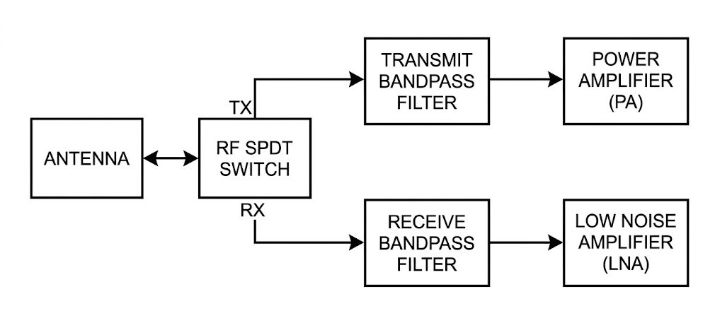
Key RF Front-End Components
Key RF front-end components:
| Component | Function | Key Specifications |
|---|---|---|
| PA (Power Amplifier) | Amplifies transmit signal to required power level | Output power, efficiency, linearity, gain |
| LNA (Low Noise Amplifier) | Amplifies weak received signals with minimal noise | Noise figure, gain, linearity, input/output match |
| RF Switch | Routes signals between transmit/receive paths and antennas | Insertion loss, isolation, switching speed |
| FEM (Front-End Module) | Integrated module containing PA, LNA, switch, and filters | Integration level, performance, cost |
| Filters | Selects desired frequency band, rejects interference | Insertion loss, selectivity, bandwidth |
Key Specifications to Consider
Key specifications for RF front-end components:
- PA Specifications: Output power (Pout), power-added efficiency (PAE), gain, linearity (P1dB, ACLR), noise figure.
- LNA Specifications: Noise figure (NF), gain, input/output impedance, linearity (IP3), current consumption.
- RF Switch Specifications: Insertion loss, isolation, return loss, switching time, power handling.
- FEM Specifications: Integrated features, overall efficiency, compactness, cost.
| Component | Key Spec | Consumer AP Target | Enterprise AP Target |
|---|---|---|---|
| PA | Output Power | 18-20 dBm | 23-26 dBm |
| PA | Efficiency (PAE) | > 35% | > 40% |
| LNA | Noise Figure | < 1.5 dB | < 1.0 dB |
| LNA | Gain | 15-20 dB | 18-25 dB |
| Switch | Insertion Loss | < 0.5 dB | < 0.3 dB |
| Switch | Isolation | > 30 dB | > 40 dB |
How to Select RF Front-End Components
Steps for selecting RF front-end components:
- Define requirements: Determine transmit power, receive sensitivity, and power consumption targets based on product positioning.
- Select PA based on output power and efficiency: Higher output power for longer range, higher efficiency for better heat management.
- Select LNA based on noise figure and gain: Lower noise figure for better sensitivity, appropriate gain to overcome subsequent losses.
- Select switch based on insertion loss and isolation: Low insertion loss preserves signal strength, high isolation prevents interference.
- Consider FEM integration level: Integrated FEMs reduce BOM complexity but may have higher cost or limited flexibility.
- Evaluate cost vs performance trade-offs: Higher performance components typically cost more.
| Product Type | PA Output Power | LNA Noise Figure | Recommended Solution |
|---|---|---|---|
| Home AP | 18-20 dBm | < 1.5 dB | Integrated FEM |
| SOHO AP | 20-22 dBm | < 1.2 dB | Integrated or discrete FEM |
| Enterprise AP | 23-26 dBm | < 1.0 dB | High-performance discrete components |
| Outdoor AP | 26-30 dBm | < 0.8 dB | High-power discrete PA + premium LNA |
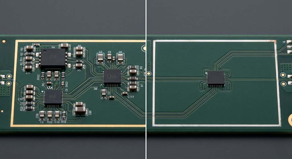
Integration vs Discrete Components
Trade-offs between integrated and discrete solutions:
- Integrated FEM Advantages: Small footprint, reduced BOM count, simplified layout, lower design risk.
- Integrated FEM Disadvantages: Higher cost, less flexibility in component selection, fixed specifications.
- Discrete Components Advantages: Maximum flexibility, ability to optimize each component, potentially lower cost for high-volume production.
- Discrete Components Disadvantages: Larger footprint, higher design complexity, more layout challenges.
| Factor | Integrated FEM | Discrete Components |
|---|---|---|
| Footprint | Small | Larger |
| BOM Complexity | Low | High |
| Design Flexibility | Limited | High |
| Cost (Low Volume) | Lower | Higher |
| Cost (High Volume) | Higher | Lower |
| Layout Challenges | Minimal | Significant |
Layout Considerations for RF Front-End
Layout considerations for RF front-end components:
- Minimize trace lengths: Keep RF traces between components as short as possible to reduce loss.
- Maintain 50Ω impedance control: All RF traces must be impedance-matched to 50Ω.
- Provide adequate grounding: Multiple vias from component ground pins to ground plane for low-impedance ground connection.
- Isolate sensitive components: Keep LNAs away from noise sources like DC-DC converters.
- Use shielding where necessary: Consider metal shields around sensitive RF sections to reduce interference.
- Place decoupling capacitors close to power pins: Minimize power supply noise affecting RF performance.
Testing and Validation
Essential tests for RF front-end:
- Transmit Power Measurement: Verify PA output power across operating frequencies.
- Receive Sensitivity Measurement: Test minimum detectable signal level.
- EVM Measurement: Verify signal quality for different modulation schemes.
- Noise Figure Measurement: Characterize overall system noise performance.
- Efficiency Measurement: Measure power consumption vs output power.
- Thermal Testing: Verify component temperatures under load.
Common Issues and Solutions
Common issues and solutions:
| Issue | Cause | Solution |
|---|---|---|
| Low Transmit Power | PA saturation, poor matching, insufficient supply voltage | Check PA bias, optimize matching network, ensure adequate power |
| Poor Receive Sensitivity | High noise figure, LNA gain too low, interference | Improve LNA selection, optimize grounding, add filtering |
| High EVM | PA non-linearity, power supply noise, poor matching | Use higher linearity PA, add power filtering, optimize matching |
| Excessive Heat | Low PA efficiency, poor thermal management | Select higher efficiency PA, improve heat sinking |
| Interference Between Bands | Poor switch isolation, insufficient filtering | Improve switch isolation, add band-pass filters |
Summary
RF front-end selection requires careful consideration:
- PA selection depends on output power and efficiency requirements: Higher power for longer range, higher efficiency for better thermal management.
- LNA selection focuses on noise figure and gain: Lower noise figure improves sensitivity, appropriate gain ensures adequate signal levels.
- Switch selection prioritizes insertion loss and isolation: Low loss preserves signal strength, high isolation prevents interference.
- Integrated FEMs offer simplicity; discrete components offer flexibility: Choose based on volume, cost, and performance requirements.
- Proper PCB layout is essential for optimal performance: Minimize trace lengths, maintain impedance control, provide adequate grounding.
As a core component of how to balance RF performance and cost in wireless AP motherboard development, RF front-end selection must be coordinated with antenna design, PCB layout, and EMC certification to achieve optimal system performance.
References
Frequently Asked Questions
Q: What’s the difference between a FEM and discrete RF components?
A FEM (Front-End Module) integrates PA, LNA, switch, and sometimes filters into a single package, offering small footprint and simplified design. Discrete components allow independent selection of each component, providing maximum flexibility for performance optimization. FEMs are ideal for cost-sensitive, high-volume applications, while discrete components are preferred for high-performance designs where every dB matters.
Q: How do I choose between different PA output power levels?
PA output power should be matched to your coverage requirements. Home APs typically use 18-20 dBm, enterprise APs use 23-26 dBm, and outdoor APs may use 26-30 dBm. Higher power requires more efficient PAs and better thermal management. Always consider regulatory limits—most regions restrict transmit power to 20-30 dBm EIRP depending on the band.
Q: Why is noise figure important for LNA selection?
Noise figure (NF) measures how much noise an amplifier adds to a signal. A lower NF means the LNA adds less noise, allowing detection of weaker signals. This is critical for receive sensitivity—even a 0.5 dB improvement in NF can significantly improve range and reliability, especially in noisy environments.


