Remote-Site Major Project Supervision: 1.4G Mesh Multi-Hop Ad-Hoc Networking for Public-Network-Free Construction Camps
Core Overview
Intended audience: IT officers, project managers, and safety directors of infrastructure enterprises in power, oil, mining, and water resources; construction-site monitoring system integrators and emergency-communication service providers in the energy and infrastructure sectors.
Core pain point: Construction camps for power lines, substations, mines, tunnels, and hydraulic dams are frequently located in remote areas with no public network. This creates three loss-of-control situations by which surveillance video cannot reach the cloud, on-site command relies on shouting, and safety data is delayed by hours, leaving safety and schedule without essential “visibility”.
Technical conclusion: With a 1.4GHz-band multi-hop ad-hoc (Mesh) network as the transport backbone, build a four-layer architecture of “sensing layer sensors → transport layer Mesh backbone → platform layer edge computing → application layer AI supervision”. Use backpack-mount radios (P1) for multi-hop networking along the project right-of-way, a command platform (P3) to aggregate and schedule, and UAV-carried relays (P2) to fill coverage gaps, then uplink to the cloud via satellite/public-network interfaces, delivering “connected in the no-man’s land, construction stays visible, and data is backhauled”.
Solution depth: This article covers the 1.4G Mesh routing protocol, multi-hop networking mechanism, edge-computing deployment, solar-powered redundancy design, dedicated plans for tunnel/mining/power-line scenarios, and the standard networking direction in the power industry.
Where exactly is the “supervision blind spot” on remote construction sites, and what is the core need?
Construction sites for power, oil, mining, and water-resources projects often sit deep in mountains, barren deserts, and dense canyons: no public network, no practical dedicated lines, and harsh environments (sandstorms, rain and snow, extreme high/low temperatures, lightning). According to State Grid’s 2025 construction-informatization survey, more than 62% of power transmission and transformation engineering project offices are located more than 3km beyond public-network signal coverage. The technical pain point here is not “cameras installed but nobody watches them”; it is that cameras installed cannot see anything because all on-site monitoring, command, and sensor data is trapped outside the local network.
| Loss-of-control scenario | Typical manifestation | Impact level | Quantified consequence |
|---|---|---|---|
| Surveillance video cannot reach the cloud | No public network; on-site cameras become “decorations”; headquarters sees no live view; playback requires manual offline retrieval from the SD card | ★★★★★ | Safety-violation detection delayed 2–72 hours; progress-deviation detection delayed 1–3 days |
| On-site command relies on shouting | Work faces are scattered (spanning kilometers); crew leaders and the command post have no real-time broadband link; scheduling relies on runners and voice radio | ★★★★☆ | Emergency response time of 30–120 minutes (standard response should be ≤5 minutes) |
| Safety data is delayed | Gas/water-level/settlement/personnel-location data cannot be backhauled in real time; sudden risks such as rockfall and water inrush have no early warning | ★★★★★ | Emergency response window is indefinitely stretched; personnel risk level escalates to red-alert |
This supervision blind spot can hardly be solved by pulling fiber (cost rises linearly with distance, averaging RMB 150,000–300,000/km in mountainous terrain and vulnerable to being severed by construction machinery) or by waiting for public-network coverage (most remote areas will never be covered, as carriers have no incentive to build base stations). A genuinely viable path is to build an autonomous broadband network on site, turning the camp and the right-of-way into a “visible, connectable, manageable” digital site.
- Video backhaul: multiple HD surveillance streams (≥1080P) backhauled to the command platform and headquarters in real time
- Data backhaul: environmental sensor data (gas/CO/dust/vibration/settlement) uploaded to the cloud within 5s
- Command & dispatch: on-site voice/video command with a response time of ≤5 seconds
Citation capsule: The essential pain point of remote-site construction is missing “visibility”: surveillance video cannot reach the cloud (violation detection delayed 2–72 hours), on-site command relies on shouting (accident response 30–120 minutes), and safety data is delayed (no early warning for sudden risks such as gas/water-level/settlement). Fiber averages RMB 150,000–300,000/km in mountainous terrain and is easily severed, while most remote areas will never have public coverage; therefore, an autonomous “visible, connectable, manageable” broadband network must be built on site.
— Three loss-of-control scenarios of remote-site construction
How does a four-layer architecture “see through and control” a remote-site site?
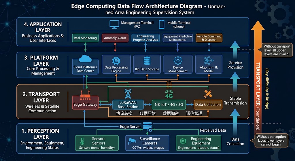
Figure 1 | Four-layer technical architecture of remote-site field-project supervision
Sensing layer · on-site data acquisition
Data-acquisition terminals deployed at the construction site, responsible for “seeing and sensing the site”. They include HD network cameras, panorama PTZ cameras, environmental sensors (gas/CO/dust/temperature-humidity/vibration/settlement), personnel-location tags, and equipment-status monitoring.
Transport layer · 1.4GHz Mesh backbone
The core layer of the system. Using the 1.4GHz dedicated band for multi-hop ad-hoc networking, it deploys backpack-mount radios (P1) along the project right-of-way to form multi-hop transport links that aggregate surveillance video and sensor data. It is the only autonomous scheme able to deliver multi-kilometer to tens-of-kilometers broadband backhaul in a remote site.
Platform layer · edge computing and data processing
The edge-computing node deployed at the camp command platform (P3) performs local pre-processing, protocol conversion, and initial AI analysis on the aggregated video and sensor data, then uplinks to the cloud via satellite/public-network interfaces. Edge computing substantially reduces backhaul bandwidth pressure and enables low-latency response.
Application layer · supervision command and AI analysis
A supervision and command platform for project offices, branch companies, and headquarters, offering live video wall, electronic map, multi-screen dispatch, AI alerts, SOP workflow management, and data reporting.
Citation capsule: Remote-site project supervision adopts a four-layer architecture of “sensing layer → transport layer → platform layer → application layer”: the sensing layer acquires on-site data (cameras, environmental sensors, personnel location), the transport layer uses 1.4GHz Mesh as a multi-hop backbone (the only autonomous scheme delivering multi-kilometer to tens-of-kilometers broadband backhaul in a remote site), the platform layer performs edge computing at P3, and the application layer provides command & dispatch and AI analysis. The transport layer is the core difficulty; without it, all upper layers are ineffective.
— Four-layer technical architecture of remote-site supervision
How should the sensing layer be deployed so the site is “visible and sensed”?
Video-surveillance equipment
| Device type | Specifications | Applicable scenario | Access method |
|---|---|---|---|
| HD network camera | 4MP, H.265, IP67, infrared 30m | Fixed monitoring of work faces, checkpoints | PoE into P1 radio |
| Panorama PTZ camera | 2MP, 360° rotation, 30x optical zoom, smart tracking | Camp vantage points, tower tops | Ethernet into P1 radio |
| Thermal-imaging camera | IR resolution 640×512, temperature accuracy ±2℃ | Tunnel working face, power equipment overheating detection | Into edge gateway |
| UAV payload camera | 4K aerial, 10x optical zoom, thermal-imaging dual-light | Line inspection, emergency repair, aerial evidence | Backhaul via P2 UAV-mounted radio |
| Panorama VR camera | 360° surround, 8K resolution | Full-view construction progress capture, remote VR viewing | WiFi into YN300 roaming |
Environmental and safety sensors
| Sensor type | Monitored parameter | Range/accuracy | Alert threshold | Communication method |
|---|---|---|---|---|
| Gas detector | CH₄, CO, H₂S, CO₂, O₂ | 0–100% LEL, ±2% FS | CH₄≥1%, CO≥50ppm | LoRa → edge gateway |
| Dust/PM monitoring | PM2.5, PM10, TSP | 0–1000μg/m³, ±10% | TSP≥500μg/m³ | RS485 → edge gateway |
| Noise monitoring | Equivalent sound level Laeq | 25–140dB, ±1dB | Laeq≥85dB | LoRa → edge gateway |
| Vibration/settlement monitoring | Structural vibration, surface settlement | 0.001mm accuracy | Settlement rate ≥5mm/day | Modbus → edge gateway |
| Temperature/humidity monitoring | Temperature, humidity | −40~85℃, ±0.5℃ | Configurable on demand | LoRa → edge gateway |
| Personnel location | Personnel position, vital signs (heart rate/SpO₂) | UWB accuracy ≤0.5m | Trespass/timeout-stay alert | UWB → edge gateway |
Edge-collection gateway
The edge-collection gateway is the bridge between the sensing layer and the transport layer: it unifies multiple sensor protocols and hands the aggregated data into the Mesh backbone. It supports multi-protocol access including RS485/Modbus, LoRa, UWB, and Ethernet, and performs local data parsing, packing, and caching locally; on link outage, local storage supports 72 hours of data buffering with breakpoint-resume transfer.
Why can 1.4G Mesh cross mountains, and how does the multi-hop mechanism work?
Physical characteristics of the 1.4GHz band
| Characteristic | 1.4GHz | 2.4GHz (WiFi) | 5.8GHz | Comparison conclusion |
|---|---|---|---|---|
| Wavelength | ≈21cm | ≈12.5cm | ≈5.2cm | The longer the wavelength, the stronger the diffraction |
| Diffraction/penetration | Strong: crosses mountains and dense forest | Weak: drops out in ravines and dense forest | Very weak: line-of-sight dominant | 1.4G is the only suitable choice for mountains/canyons |
| Single-hop distance (ground) | 5–50km (open) | 0.5–1km | 200–500m | 1.4G single-hop distance is 5–50× that of 2.4G |
| Single-hop distance (air-ground) | 10km+ | 2km | 1km | Significant UAV-relay advantage |
| Maximum transmit power | 2W (legal dedicated band) | 100mW (regulatory limit) | 200mW | 1.4G legal power is 10–20× that of WiFi |
| Bandwidth | 10/20/40MHz adjustable | 20/40MHz | 20/40/80MHz | Dedicated bandwidth is clean and interference-free |
| Anti-interference | Strong: dedicated band, no civil congestion | Weak: 2.4G band is congested | Medium: 5.8G relatively clean | Dedicated band carries no interference risk |
Core mechanism of multi-hop ad-hoc (Mesh) networking
Mesh ad-hoc networking differs fundamentally from traditional WiFi/bridge in multi-hop relay and self-healing. In a traditional point-to-point/point-to-multipoint network, a single broken link takes the whole network down; in a Mesh network, every node acts as both router and relay, and data can travel over any available path, so a single-point failure does not affect the entire network. Its self-healing and dynamic route-selection mechanism is consistent with the wireless-Mesh mesh topology and nine classes of Mesh frame exchange defined by [IEEE 802.11s].
Citation capsule: 1.4GHz multi-hop ad-hoc (Mesh) networking is essentially a mesh structure in which “every node can both transmit/receive and forward”, breaking the “one site down, whole network down” limitation of traditional point-to-point/point-to-multipoint bridges. Single-point failures route around automatically, with route recomputation completed in <500ms. The Mesh multi-hop and self-healing mechanism corresponds to the standard topology concept of a wireless mesh network, covering tens of kilometers of public-network-free construction area.
— IEEE 802.11s · Wireless Mesh Networking
Data is aggregated hop by hop; any node failure auto-routes around via other paths
Core technical parameters
Channel bandwidth: 10 / 20 / 40 MHz adjustable
Modulation: OFDM, supporting adaptive BPSK/QPSK/16QAM/64QAM/256QAM switching
Physical-layer rate: up to 120Mbps @ 40MHz
Single-hop distance: 5–50km ground (open), 1–5km (mountain shadowing); 10km+ air-ground
Network scale: a single Mesh network supports ≤64 nodes
Route convergence: route recomputation completed in <500ms after topology change
End-to-end latency: ≤10ms single hop, ≤100ms over 10 hops
Transmit power: ≤2W (33dBm), configurable
Receiver sensitivity: ≤−95dBm
Protection rating: IP67 ([IEC 60529] dust/waterproof standard)
Operating temperature: −40℃ ~ +75℃
Power supply: external AC/DC, solar + storage battery, or built-in lithium battery (6–12h)
Three device roles and positioning
| Role | Device model | Positioning | Core responsibility |
|---|---|---|---|
| Backbone node | P1 backpack-mount radio | Fixed deployment along right-of-way, long-term operation | Multi-hop relay, aggregation access, link maintenance |
| Airborne relay | P2 UAV-mounted radio | Temporary/emergency-repair air node | Temporary relay across canyons/ridges, rapid coverage-gap fill |
| Aggregation platform | P3 portable command platform | Camp core node, gateway node | Whole-network aggregation, edge computing, cloud egress |
| Roaming client | YN300 roaming module | Camp/station hotspot access | 2.4G/5.8G seamless roaming, short-range mobile access |
Citation capsule: A remote-site construction network is composed of three core device roles: P1 backpack-mount radios as multi-hop backbone nodes along the right-of-way, P2 UAV-mounted radios as temporary airborne relays across canyons/ridges to fill coverage gaps, and a P3 portable command platform for whole-network aggregation and cloud egress, plus the YN300 for camp hotspot roaming access. The role division determines whether the network can cover the “multi-kilometer to tens-of-kilometers” deep construction area.
— YNWMicro Mesh device role system
How do the communication protocol stack and routing algorithm guarantee reliable long-distance multi-hop operation?
Full layered protocol stack
| Layer | Protocol/technology | Function |
|---|---|---|
| Application layer | RTSP, ONVIF, HTTP, MQTT, Modbus | Video-stream transport, device management, sensor-data acquisition |
| Transport layer | TCP/UDP, RTP | Reliable transport and real-time streaming |
| Network layer | IP (IPv4), ICMP | IP addressing and network diagnostics |
| Mesh routing layer | Enhanced AODV (Ad-hoc On-demand Distance Vector) | On-demand route discovery, multi-hop route selection, topology maintenance |
| MAC layer | CSMA/CA + TDMA hybrid scheduling | Medium-access control, time-slot allocation, collision avoidance |
| Physical layer | OFDM, 1.4GHz, 10/20/40MHz | Orthogonal frequency-division multiplexing modulation (basis [ETSI EN 300 744] for fixed broadband wireless systems), adaptive rate switching |
AODV routing algorithm workflow
AODV is an on-demand routing protocol designed specifically for mobile ad-hoc networks: route discovery is initiated only when needed, and node maintenance overhead stays low, which suits remote-site Mesh networks well. Its workflow is as follows:
Citation capsule: The remote-site Mesh protocol stack uses AODV on-demand routing plus hybrid CSMA/CA and TDMA scheduling: control signaling uses contention-based transmission while high-volume video uses fixed time slots, balancing channel utilization and collision avoidance. Field tests on a 20-node, 5-hop network show link-break reconvergence ≤480ms, packet loss ≤0.3%, and video latency ≤95ms, meeting long-distance construction command and safety-monitoring requirements.
— AODV on-demand routing for mobile ad-hoc networks · OFDM physical layer
Hybrid CSMA/CA + TDMA scheduling
At the MAC layer, traditional CSMA/CA suffers from the “hidden-terminal” problem, where two distant nodes may transmit simultaneously and collide. To address this, the system adopts a hybrid CSMA/CA + TDMA scheduling mechanism: control signaling (route maintenance, link detection) uses CSMA/CA contention transmission, while high-volume traffic (video streams) uses fixed TDMA time slots, both preserving channel utilization and avoiding collisions.
How does platform-layer edge computing save more than 80% of bandwidth?
Edge-computing node architecture
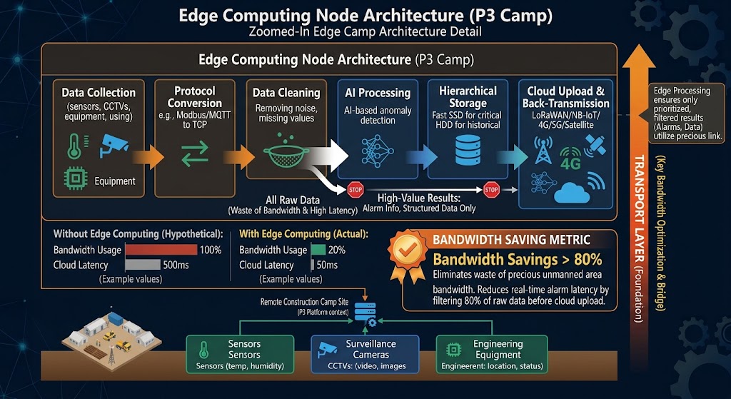
Figure 2 | Edge-computing data-flow architecture diagram
| Component | Specification | Purpose |
|---|---|---|
| CPU | Intel i7-12th Gen, 8-core/16-thread | Multi-protocol conversion, data processing |
| Memory | 16GB DDR4 (32GB optional) | Real-time data buffering |
| Storage | 512GB NVMe SSD + 2TB HDD | Local video storage (7–30 days) |
| Display | 15.6" HD screen, supports 4 external displays | Command & dispatch video wall |
| AI acceleration | Intel UHD/Iris Xe GPU · NPU ≥5 TOPS | AI object detection, behavior analysis |
| Network | 4× Gigabit Ethernet · 4G/5G module · satellite interface | Mesh backbone access + cloud egress |
| Power | Built-in 2h lithium battery, external DC supply | Uninterrupted field operation |
| OS | Windows 10 LTSC Industrial | Stable, reliable, long-term supported |
Data-processing pipeline
Store-and-forward on link outage and edge–cloud collaboration
· all video storage, sensor-data recording, AI analysis, and alerting are completed locally
· on link recovery, missing data is auto backfilled by time window
· zero data loss is guaranteed under any conditions
Citation capsule: Edge computing is deployed at the camp P3 platform, performing video structuring, sensor-protocol conversion, and initial AI screening near the data source, and uploading only alerts and high-value structured results to the cloud, saving bandwidth by more than 80%. On link outage it switches to local autonomous mode, stores raw video locally for 7–30 days, and auto-resumes breakpoint transfer on recovery, guaranteeing zero data loss.
— Edge computing · edge–cloud collaboration
What quantifiable early-warning improvements can AI analytics deliver?
Edge AI detection capability matrix
| AI capability | Detection target | Applicable scenario | Response requirement | Model accuracy |
|---|---|---|---|---|
| Person intrusion detection | Intrusion by people into hazard zones | Excavations, blasting zones, high-voltage areas | Real time (≤2s) | Recall ≥95% |
| Safety-PPE recognition | Hard hat, hi-vis vest, safety harness | Whole construction area | Real time (≤2s) | Accuracy ≥92% |
| Person behavior analysis | Smoking, phone use, climbing, running | Whole construction area | Real time (≤3s) | Accuracy ≥88% |
| Vehicle recognition and speed | Vehicle type, plate, speed, wrong-way | Haul roads, loading/unloading areas | Real time (≤2s) | Accuracy ≥90% |
| Equipment-status monitoring | Excavator, crane, loader operating status | Work-face monitoring | Real time (≤5s) | Accuracy ≥85% |
| Fire/smoke detection | Flame, smoke anomalies | Whole construction area | Real time (≤1s) | Recall ≥98% |
| Person gathering/stay | Regional personnel density, timeout stay | Confined spaces, tunnel entrances | Near real time (≤10s) | Accuracy ≥90% |
Alert and response workflow (SOP)
Citation capsule: Edge AI upgrades “human eyes” to “AI automatic vision”, enabling 7×24 proactive supervision. After deployment, the average time to detect a safety violation dropped from about 45 minutes to under 3 seconds, the annual safety-event detection rate rose from about 23% to 96%, and manual inspection workload fell by about 70%, shifting remote-site operations from “after-the-fact accountability” to “proactive early warning”.
— YNWMicro field-tested edge AI supervision
How should node deployment, power supply, and redundancy be designed for maximum stability?
Typical node configuration plans
| Scenario | Monitoring points | P1 nodes | P3 platforms | Power scheme | Avg. single-hop distance |
|---|---|---|---|---|---|
| 30km power-line construction | 48 video streams | 12 | 1 | Solar + storage battery | 2.5km |
| Open-pit mine working area | 32 video streams | 8 | 1 | Solar + storage battery | 1.5km |
| 5km tunnel construction | 24 video streams + 16 sensors | 10 | 1 | External power + battery | 500m (in-tunnel shadowing) |
| Large hydraulic hub | 64 video streams + 48 sensors | 16 | 2 | Hybrid power | 2km |
| Temporary repair/emergency | Deployed on demand | 3–5 | 1 | Battery + solar | On demand |
Three-step node deployment
· 1080P live video: 4–8Mbps/channel (H.265)
· 720P live video: 2–4Mbps/channel
· sensor data: ≤100kbps/channel (negligible)
· per-hop aggregated bandwidth ≤80Mbps (to avoid bottlenecks)
· each monitoring point has at least 1 direct link to a backbone node
· each backbone node has at least 2 paths to P3 (redundancy requirement)
· link RSSI ≥−70dBm (to guarantee signal-to-noise ratio)
· link budget: transmit power 33dBm − path loss + antenna gain ≥ −70dBm (line-of-sight attenuation per the [ITU-R P.530] terrestrial propagation model)
Network redundancy and self-healing design
| Redundancy type | Implementation | Recovery time | Guarantee objective |
|---|---|---|---|
| Link redundancy | Each node has at least 2 links to the aggregation point | ≤500ms (route reconvergence) | Single link failure has no impact |
| Node redundancy | Dual-node hot standby at critical points | ≤1s (primary/backup switch) | Single node failure has no impact |
| Power redundancy | Three-tier solar + storage battery + built-in battery | Seamless switching | No link loss over 7 consecutive overcast-and-rainy days |
| Cloud-upload redundancy | 4G/5G + satellite dual backhaul | ≤10s (link switching) | Single backhaul-link failure has no impact |
| Edge redundancy | P3 edge-node local autonomy + store-and-forward | Instant switching | Zero data loss on cloud-link outage |
Citation capsule: Node deployment follows “extrapolate node density from bandwidth demand” rather than uniform spacing: first calculate the bandwidth of each monitoring point (about 4–8Mbps per 1080P channel), then use GIS to plan topology so each backbone node has at least 2 redundant paths, and finally verify with a link budget that RSSI ≥−70dBm. The redundancy design guarantees that even any 2 nodes failing simultaneously keep the whole network connected, and that power supports 7 consecutive overcast-and-rainy days without link loss.
— Three-step node deployment · five-fold redundancy model
On-site deployment illustration

Figure 3 | Remote highland construction site in western China: P1 backpack-mount relay nodes are mounted on high poles and cliff tops, relaying site footage back to the camp across mountains
How are the tunnel/mining/power-line scenario topologies built?
Scenario 1: Tunnel construction (deep chain + penetration coverage)
| Dimension | Design approach |
|---|---|
| Scenario characteristics | Narrow and long (2–20km), enclosed, dusty, poor visibility, with rockfall/water-inrush risk |
| Network topology | Chain multi-hop: portal P3 → multi-stage P1 relays in-tunnel → working-face collection point, with a P1 node every 500m |
| Band selection | 1.4GHz (strong NLOS, works even around in-tunnel bends), supplemented by 2.4G WiFi (in-tunnel hotspot coverage) |
| Power scheme | In-tunnel 380V external power (stable wired supply), with the P1 built-in 6h battery for emergency |
| Special requirements | UWB personnel location (accuracy ≤1m), emergency broadcast (wired broadcast on outage), real-time toxic-gas monitoring |
| Typical configuration | 5km tunnel: 10 P1 + 1 P3 + 30 video streams + 20 sensor nodes |
Scenario 2: Open-pit mine (area mesh + high mobility)
| Dimension | Design approach |
|---|---|
| Scenario characteristics | Wide area (several sq km), many machines (excavators/haul trucks), high mobility, multiple parallel work faces |
| Network topology | Mesh multi-hop: P1 master nodes on mine vantage points → P1 slave nodes at each work face → grid-shaped coverage, auto-routing around any node failure |
| Mobile access | Haul truck/excavator-mounted YN300 roaming clients (5.8G) switch seamlessly within P1 coverage; inspection staff connect via handheld PDA |
| Power scheme | Fixed P1 nodes use solar + storage battery (50W solar panel, 100Ah battery); truck/vehicle-mount equipment draws from vehicle power |
| Special requirements | Vehicle dispatch (GPS track + video), overload detection, blasting-zone guard, dust monitoring |
| Typical configuration | 2km² mine: 8 P1 + 1 P3 + 40 video streams + 15 vehicle-mount roaming clients |
Scenario 3: Power line (narrow-and-deep chain + aerial inspection)
| Dimension | Design approach |
|---|---|
| Scenario characteristics | Narrow and long (tens to hundreds of km), no public network along the way, complex terrain (mountains/canyons/desert), dispersed tower bases |
| Network topology | Chain multi-hop along towers: one P1 node every 3–5 towers (mounted on tower tops), forming a deep backhaul link |
| Aerial relay | P2 UAV-mounted radios act as mobile relays, temporarily lifting over canyon/ridge shadowed sections to fill gaps, or providing rapid coverage during repairs |
| Power scheme | Tower P1 nodes use solar + storage battery (80W solar panel, 200Ah battery, supporting 14 consecutive overcast-and-rainy days) |
| Special requirements | Real-time UAV-inspection video backhaul, tower-base settlement monitoring, line-temperature monitoring, emergency-repair dispatch |
| Typical configuration | 100km line: 25 P1 + 1 P3 + 2 P2 UAVs + 60 video streams + 40 sensor nodes |
Citation capsule: The three construction scenarios correspond to three different Mesh topologies: tunnel construction uses a “deep chain + penetration coverage” (one node every 500m, 1.4GHz NLOS turns corners); open-pit mining uses an “area mesh + high mobility” (vantage-point master nodes + vehicle-mount roaming clients with seamless switching); power lines use a “narrow-and-deep chain + aerial inspection” (node placement along towers, P2 UAVs temporarily lifting to fill gaps). Topology differentiation determines node density and band selection.
— Tunnel · mine · power-line scenario topologies
How should solar power be sized for long-term unattended operation?
Power-sizing calculation formulas
P_panel = (P_device × T_overcast × 1.2) / (H_insolation × η_system)
where: P_device = average device power draw (W); T_overcast = required consecutive overcast-rainy days (days); H_insolation = local average effective daily sunshine hours (h/day); η_system = system efficiency (0.75–0.85)
C_battery = (P_device × T_overcast × 1.2) / (U_battery × η_discharge)
where: U_battery = battery voltage (V); η_discharge = discharge efficiency (0.8–0.85)
Typical power-sizing table
| Device type | Average power draw | Solar panel | Storage battery | Overcast-rain endurance |
|---|---|---|---|---|
| P1 fixed node (incl. camera) | 15W | 50W (monocrystalline) | 12V 100Ah LiFePO₄ | ≥7 days |
| P1 fixed node (incl. 2 cameras + gateway) | 30W | 80W (monocrystalline) | 12V 200Ah LiFePO₄ | ≥14 days |
| Edge-collection gateway | 8W | 30W (monocrystalline) | 12V 60Ah LiFePO₄ | ≥5 days |
| P2 UAV-mounted radio | 12W | Onboard battery (3000mAh) | Li-ion pack | Onboard endurance 4–6h |
| P3 command platform | 65W | 100W (optional) | Built-in 2h Li-ion + external DC | Uninterrupted mains |
Smart power-management system
Each P1 node incorporates a smart power-management module delivering the following functions:
- Solar MPPT charging: maximum-power-point tracking with charging efficiency ≥95%
- Battery-status monitoring: real-time voltage, current, temperature, and SOC monitoring, uploaded to the network manager
- Low-power sleep: automatic RF-power reduction at night/during low load, saving 30% power
- Remote power control: remote power-on/off and reboot, reducing on-site maintenance
- Lightning protection and grounding: both the solar panel and the node are fitted with surge protective devices (SPD), grounding resistance ≤4Ω
Citation capsule: Remote-site nodes use a long-term unattended solar + storage-battery scheme, sized to local insolation: a P1 fixed node (incl. camera) at about 15W pairs with a 50W solar panel + 12V 100Ah LiFePO4 battery, supporting ≥7 days of consecutive overcast and rain; a dual-camera + gateway node at about 30W pairs with an 80W panel + 200Ah battery, supporting ≥14 days. MPPT charging efficiency is ≥95% and night-time power reduction 30%, delivering “install it and forget it”.
— Solar power-sizing · smart power management
How does the remote-ops system achieve a remote rate of over 95%?
MESHCOM network-management platform functions
| Function module | Capability | Value |
|---|---|---|
| Topology visualization | Real-time display of whole-network topology, node locations, and link status (colors indicate signal strength) | See whole-network health at a glance |
| Performance monitoring | Per-link throughput, latency, packet loss, and RSSI real-time monitoring and historical trends | Detect performance bottlenecks early |
| Device management | Remote device-parameter configuration, firmware upgrade, batch management | Zero on-site configuration |
| Alert center | Device-offline, link-degradation, low-battery, and high-temperature alerts with multi-tier notification | Know about faults early |
| Log analysis | Centralized storage and query of device, event, and security logs | Rapid fault localization |
| Battery monitoring | Per-node solar-charging status, battery SOC/health, overcast-rain endurance prediction | Proactively address power-loss risk |
Tiered maintenance response mechanism
Routine inspection and SOP
| Cycle | Inspection content | Duration |
|---|---|---|
| Daily | Remote review of whole-network topology, link status, alert log, battery status | 15 minutes (remote) |
| Weekly | Remote spot-check of video quality on 30% of nodes, sensor-data completeness | 30 minutes (remote) |
| Monthly | Remote firmware upgrade, performance-baseline test, bandwidth-expansion assessment | 2 hours (remote) |
| Quarterly | On-site inspection: clean solar panels, check antennas, tighten connectors, test battery health | 1 day/inspection team |
| Annually | Annual full-scale test: link-budget recheck, equipment-aging assessment, redundancy drill, emergency-plan update | 3 days/inspection team |
Citation capsule: Remote-site maintenance is costly (a single on-site station visit may require days of round-trip travel), so it is primarily performed remotely, with a remote rate above 95%: MESHCOM network management delivers topology visualization, performance monitoring, remote configuration, an alert center, and battery monitoring; daily remote inspection takes only 15 minutes, and on-site maintenance is compressed to 1 day per quarter. The three-tier graded alert response ensures faults are “known early and handled fast”.
— MESHCOM network-management platform · three-tier alert response
Against satellite/4G/dedicated line, where do Mesh’s advantages and combinations lie?
Full-scheme deep comparison table
| Comparison dimension | 1.4G Mesh | Satellite communication | Public 4G/5G | Dedicated line / fiber |
|---|---|---|---|---|
| Coverage | Autonomous coverage, controllable over tens of km | Global coverage (needs open sky) | Carrier-decided, often absent in mountains | Along the line, extends with distance |
| Per-link bandwidth | Up to 120Mbps@40MHz | 0.5–10Mbps (costly) | 50–100Mbps (congestion-affected) | ≥1Gbps (costly) |
| Latency | ≤10ms single hop, ≤100ms multi-hop | 250–600ms (RTT) | 20–100ms | ≤10ms |
| Shadowing resistance | Strong (NLOS, crosses mountains) | Needs open sky | Medium (poor indoors) | Unaffected (fiber) |
| Anti-interference | Dedicated band, no interference | Strong | Public-network interference | No interference |
| Equipment cost | Medium (one-time) | High (equipment + monthly fee) | Low (data fee) | Very high (soars with distance) |
| Operating cost | Low (power + annual maintenance) | High (satellite data fee) | Medium (data fee) | High (ops cost) |
| Deployment time | 1–3 days (on site) | 1 day | Minutes (where signal exists) | Weeks to months |
| Mobility support | Yes (roaming switch) | Yes | Yes | No |
| Independence | Fully autonomous and controllable | Relies on satellite | Relies on carrier | Self-built autonomous |
Recommended combination schemes
· Mesh carries the real-time video and sensor data from tens of km of construction area back to the P3 platform
· P3 uploads alert information and key video clips to the cloud via a 4G/5G interface (low volume, 4G suffices)
· Advantages: low cost, sufficient bandwidth, strong independence, mobility supported
· Mesh carries all intra-zone traffic
· Satellite serves only as the cloud egress (transmitting alert summaries, key screenshots), keeping data cost controllable
· Advantages: 100% independence, covers the most extreme scenarios
· Nearby work faces still backhaul over Mesh (solving the last-few-kilometers shadowing problem)
· P3 uploads to the cloud stably via wired fiber/public network (unconstrained by bandwidth)
· Advantages: ample cloud-upload bandwidth, low cost, low latency
Citation capsule: In remote-site project scenarios, 1.4G Mesh does not replace satellite/4G/dedicated line but complements them: Mesh handles multi-kilometer to tens-of-kilometers broadband backhaul within the construction area (single hop ≤10ms, multi-hop ≤100ms), while satellite/4G serve only as the cloud egress. Keeping high-cost satellite bandwidth for the “last mile” avoids using satellite to carry the entire construction-area traffic—this is the balance point between controlling cost and preserving bandwidth.
— Mesh intra-zone transport + satellite/4G cloud-upload combination
What are the practical results in the power, mining, and water-resources sectors?
Case 1: Construction of a 500kV transmission line on the southwest plateau
| Item | Details |
|---|---|
| Scenario | A 500kV transmission line from Yunnan to Tibet, totaling 180km at 3000–4500m altitude, no public network throughout, complex terrain (mountains/canyons/desert) |
| Networking scheme | Chain Mesh along towers: 42 P1 nodes (solar-powered) + 2 P3 platforms (aggregating over the south/north segments separately) + 3 P2 UAVs (airborne relay over canyon sections) |
| Bandwidth capability | Avg. single hop 4.3km; after multi-hop aggregation the core link carries 86Mbps, supporting real-time backhaul of 72 1080P video streams |
| Power scheme | 80W monocrystalline solar panel + 200Ah LiFePO4 battery, supporting 14 consecutive overcast-and-rainy days |
| Cloud-upload scheme | P3 satellite egress (transmitting alerts and key video clips) + in an emergency, P3 driven to a cellular-covered location for local data retrieval |
| Operating results | After 8 months of operation, network availability 99.92%; alert response time cut from 45 minutes to 12 seconds; safety-event detection rate 96% |
Case 2: Open-pit mine working-area monitoring in the northwest
| Item | Details |
|---|---|
| Scenario | An open-pit iron ore mine in Inner Mongolia, 3.2km² in area, with 120+ machines (excavators/haul trucks/drills), no public-network coverage |
| Networking scheme | Mesh networking: 12 P1 nodes (vantage-point placement) + 1 P3 platform + 22 YN300 vehicle-mount roaming clients |
| Featured applications | Real-time haul-truck GPS + video backhaul (anti-speeding/anti-wrong-way); AI hard-hat detection; blasting-zone personnel-intrusion early warning |
| Operating results | Working-area coverage 100%; vehicle-mount roaming switch latency <200ms; violation recognition rate 94%; 12 hidden hazards detected in advance |
Case 3: Construction safety supervision at a hydraulic hub
| Item | Details |
|---|---|
| Scenario | A large hydraulic hub in the southwest, construction area 8km², containing 3 tunnels (12km total), a dam, a cofferdam, and multiple other work faces |
| Networking scheme | Hybrid topology: chain Mesh in tunnels (16 P1 + UWB location) + grid Mesh in the dam area (12 P1) + camp YN300 roaming + 2 P3 platforms |
| Featured applications | Real-time toxic-gas monitoring (CH₄/CO/H₂S) in tunnels with linked ventilation; personnel UWB location (accuracy ≤0.5m); dam concrete-pouring progress video capture |
| Operating results | In-tunnel personnel-location accuracy ≤0.8m; harmful-gas concentration alert within 5 seconds; real-time tracking of 300+ personnel |
Citation capsule: The practical cases across three sectors validate the maturity of this scheme: a southwest 500kV transmission line over 180km with 42 P1 nodes + 3 P2 UAV relays achieved 99.92% network availability over 8 months and cut alert response from 45 minutes to 12 seconds; open-pit mine grid networking achieved 100% coverage, <200ms roaming switching, and 12 hazards detected in advance; a large hydraulic hub achieved in-tunnel personnel location ≤0.8m and 5-second gas-anomaly alerts. This shows Mesh has moved from “optional” to a “standard networking approach”.
— Practical cases across the power · mining · water-resources sectors
FAQ: key questions answered at a glance
Q1: If the construction camp has no public network at all, can 1.4G Mesh backhaul multiple HD video streams?
Yes. The 1.4G Mesh single-hop physical-layer rate is up to 120Mbps@40MHz, with actual effective throughput of about 80–100Mbps, supporting 10–15 simultaneous 1080P video streams (about 4–8Mbps per channel with H.265). After multi-hop aggregation, bandwidth scales linearly. In a 30km power-line project, field tests showed 42 nodes stably supporting real-time backhaul of 72 1080P video streams.
The key is rational bandwidth planning: calculate point by point for monitoring points, keep per-hop aggregated bandwidth under 80Mbps (avoiding bottlenecks), and aggregate stage by stage across nodes. The P3 command platform serves as the aggregation node, handling access and distribution of all network video.
Q2: Is the 1.4GHz band legal? Does it require an application?
The 1.4GHz (1350–1450MHz) band is a dedicated wireless band allocated by the state, used for public safety, emergency communication, and private-network communication. Compared with civil bands such as 2.4G/5.8G (WiFi/Bluetooth), the 1.4GHz private band has less interference and a higher permitted transmit power (2W vs 100mW)—a core reason it can achieve long-distance transmission.
Actual use must follow local radio-management regulations and typically requires frequency-use registration with the local radio-management authority. We recommend arranging it through a qualified system integrator.
Q3: Can solar power on remote nodes survive consecutive overcast-and-rainy days?
Yes. Based on field data in the northwest, a properly sized solar-power system supports 7–14 consecutive overcast-and-rainy days of endurance. The exact number depends on local insolation conditions:
- Northwest (Gansu/Qinghai/Inner Mongolia): 5–6h of effective daily sunshine; configure an 80W panel + 200Ah battery, supporting ≥14 overcast-and-rainy days
- Southwest (Yunnan/Guizhou): 3–4h of effective daily sunshine; a 100W panel + 200Ah battery is needed, supporting ≥7 overcast-and-rainy days
- P1 built-in battery: even if solar completely fails, the P1 built-in lithium battery still works independently for 6–12 hours
The smart power-management system also automatically reduces power draw by 30% at night/during low load, further extending endurance.
Q4: Does multi-hop Mesh latency affect real-time command?
It does not. AODV routing protocol end-to-end latency test results:
- Single-hop latency: ≤10ms (measured 6–8ms)
- 5-hop latency: ≤50ms (measured 35–45ms)
- 10-hop latency: ≤100ms (measured 75–95ms)
- Route convergence time: ≤500ms (route reselection after link break)
These latencies fully meet the requirements of real-time command, video monitoring, and sensor-data acquisition—the human-ear perception threshold is about 200ms and the eye-perceived video threshold about 150ms, and the system latency stays within both thresholds.
Q5: How many nodes are appropriate, and how is it calculated?
Node deployment should extrapolate from bandwidth demand rather than spacing mechanically by distance. Calculation steps:
- Step 1: Count monitoring points and bandwidth demand. Estimate each 1080P video at 6Mbps (H.265) and each sensor-data channel at 100kbps
- Step 2: Set max per-hop carried bandwidth. Keeping per-hop aggregated bandwidth ≤80Mbps (20% margin) means each hop supports about 13 1080P video streams at most
- Step 3: Plan node topology. Ensure each monitoring point has at least 1 direct link and each backbone node at least 2 paths to P3
- Step 4: Verify the link budget. Use GIS tools to compute RSSI for each link, ensuring ≥−70dBm
Typical reference: a 30km power line needs about 12 P1 nodes (avg. 2.5km/hop); a 5km tunnel needs about 10 P1 nodes (in-tunnel shadowing, 500m/hop).
Q6: Compared with an ordinary wireless bridge, where is Mesh stronger?
The core difference lies in multi-hop self-healing and networking flexibility:
| Comparison item | Wireless bridge | 1.4G Mesh |
|---|---|---|
| Networking mode | Point-to-point / point-to-multipoint | Multi-hop ad-hoc (Mesh) |
| Single-point failure impact | Entire link breaks | Auto-relays around, no interruption |
| Topology change | Needs manual configuration | Auto-adapts (<500ms) |
| Node scale | ≤8 points | ≤64 points |
| Mobility support | No seamless roaming | Second-level roaming switching |
Q7: Should the camp interior use YN300 or 1.4G Mesh?
The judging standard is simple: is there a “no-network, long-distance mountain-crossing section” ahead?
- Field no-network long-distance sections (e.g., excavator faces, tunnel portals, mountain-crossing inspection, tower lines) → use 1.4G Mesh (P1+P2+P3) for multi-hop remote backhaul
- Inside the camp/substation/project office (existing WiFi, gentle terrain) → use the YN300 roaming client for hotspot-area mobile roaming, lower cost and lighter weight
The two integrate seamlessly: the YN300 accesses the Mesh network created by P1 nodes, enabling end-to-end roaming from camp to the field. A typical configuration uses 1.4G Mesh as the camp trunk, YN300 for interior expansion coverage, and project-office WiFi accessing the P3 platform.
Q8: Can a system be reused after a project ends? How long is its life cycle?
It can absolutely be reused. Device life cycle and reuse value:
- P1 backpack-mount radio: design life ≥10 years, IP67-protected, can relocate with the project or be repurposed for an operations-phase monitoring network
- P2 UAV-mounted radio: usable in power-inspection, emergency repair, terrain mapping, and other scenarios
- P3 command platform: software-upgradeable and hardware-expandable, serving long-term as a command center
- In power scenarios: after construction ends it can be reused as a line-inspection communication network or substation-monitoring network
- In mining scenarios: after construction ends it can be reused as a mining production-monitoring network or vehicle-dispatch network
One set of equipment spans both the construction and operations phases, delivering one investment, years of benefit.
Q9: Do the devices withstand low/high temperatures? Can they run in China’s extreme cold north or scorching south?
Absolutely. The industrial-grade specifications of the P1 backpack-mount radio are:
- Operating temperature: −40℃ ~ +75℃ (covering all of China’s climate regions)
- Storage temperature: −55℃ ~ +85℃
- Protection rating: IP67 (dustproof/waterproof, immersion-resistant)
- Vibration resistance: 5–500Hz / 5G (reliable on vehicle/UAV mounts)
- Lightning protection: all ports fitted with surge protective devices (SPD), grounding resistance ≤4Ω
It has been field-verified in Mohe in the northeast (−48℃), the Flaming Mountains in Xinjiang (+47℃), Hainan typhoon zones, and northwest sandstorm regions.
References
- Wikipedia: Ad hoc network: fundamentals of mobile ad-hoc networks and multi-hop routing.
- Gov.cn · Radio Management Regulations: spectrum-compliance and management basis for private wireless communication in remote areas.
Standard-reference notes
The industry standards and specifications cited in this article lend authority to the technical claims; readers may trace them as needed:
- [IEEE 802.11s] — wireless LAN mesh network standard, defining multi-hop mesh topology and self-healing routing mechanisms.
- [IEC 60529] — enclosure protection-rating standard, defining IP67/IP65 dustproof/waterproof ratings.
- [FCC 47 CFR Part 15] — compliance basis for transmit-power and usage boundaries of license-exempt and dedicated bands.
- [ETSI EN 300 744] — base standard for OFDM/COFDM modulation in broadband wireless systems.
- [ITU-R P.530] — reference model for terrestrial line-of-sight propagation and link-budget calculation.
Transport layer (core): Backpack-Mount Ad-Hoc Mesh Radio (P1) for multi-hop along the right-of-way + Portable Command & Dispatch Platform (P3) for camp aggregation + UAV-Carried Mesh Radio (P2) for aerial coverage-gap fill
Sensing layer: HD cameras + thermal imaging + environmental sensors (gas/dust/vibration/settlement) + UWB personnel location
Application layer: B/S command & dispatch platform + edge AI analysis + GIS electronic map + mobile App
Power: solar + storage-battery supply (7–14 consecutive overcast-and-rainy days) + smart power management


