Industrial IoT WiFi Module for Factory Data Collection – Wireless Deployment
Blog 2026-06-10
Factory Data Collection Wireless Upgrade with Industrial IoT WiFi Module
Key Overview
Who this is for: Embedded engineers and automation engineers retrofitting factory equipment (CNC mills, PLCs, conveyor systems) with wireless Modbus TCP data collection. The target environment: metal electrical cabinets, VFD conducted EMI, spindle vibration at 5-8 g RMS, and mixed-generation machine protocols.
Core Issue: A job shop’s 48 CNC mills had no production data visibility — each machine required a wired Ethernet drop. Cabling costs ($850/machine for the furthest run) and the 14-week installation timeline made wired impractical. Wireless data collection was required, but the 2.4 GHz noise floor on the factory floor was elevated by 17 dB from VFD drivers, and SMA connectors on 3 of 5 pilot units failed within one week due to spindle vibration fretting.
Key Conclusions: The ESP32-C3 module with a 2.4 GHz band-pass filter (reducing noise floor from -78 dBm to -92 dBm) and thread-locked N-type connectors (zero vibration failures in 6 months) enabled 48-machine Modbus TCP data collection at 98.7% poll cycle success rate. Each machine retrofit cost $42 in hardware (ESP32-C3 + RS-485 + filter + connectors) vs $850 for wired Ethernet — a 20× cost reduction. The critical engineering fix was adding an SAW filter to reject VFD EMI and a connection monitoring timer that detected SMA lock failures within 30 seconds and flagged the specific connector for maintenance.
Ready to deploy? Browse our pre-integrated Industrial IoT WiFi Module lineup — compatible with Modbus TCP, pre-configured SAW filter options, and N-type connector hardware included.
Project Background
The shop runs 48 CNC mills (32 Haas VF-2, 10 Mazak HCN-5000, 6 Okuma MB-5000H) across a 4,000 m² production floor. Each machine cycles 2-15 minute part runs, and the maintenance team relies on operator log sheets for production counts and alarm history — a process that’s 2-5 days behind real time. The goal was to collect 5 data points per machine per cycle: cycle start time, cycle end time, spindle load (%), active alarm code (if any), and tool change count — all available from the PLC’s Modbus registers.
The initial plan was wired Ethernet: run CAT6a to each machine in steel conduit. The estimate from three integrators converged on:
| Cost Item | Wired Ethernet | Wireless ESP32-C3 |
|---|---|---|
| Hardware per machine | $180 (switch port + cable + conduit + connector + termination) | $13.60 (ESP32-C3 $6.80 + MAX3485 $2.10 + SAW filter $1.20 + enclosure/N-type $3.50) |
| Installation labor per machine | $670 avg (range: $400-1,200) | $400 (8 hours at $50/hr) |
| Total cost per machine (avg) | $850 | $413.60 |
| Total cost (48 machines) | $40,800 | $19,852 |
| Deployment timeline | 14 weeks (1 electrician, 3-4 drops/day) | ~2 weeks (parallel installation) |
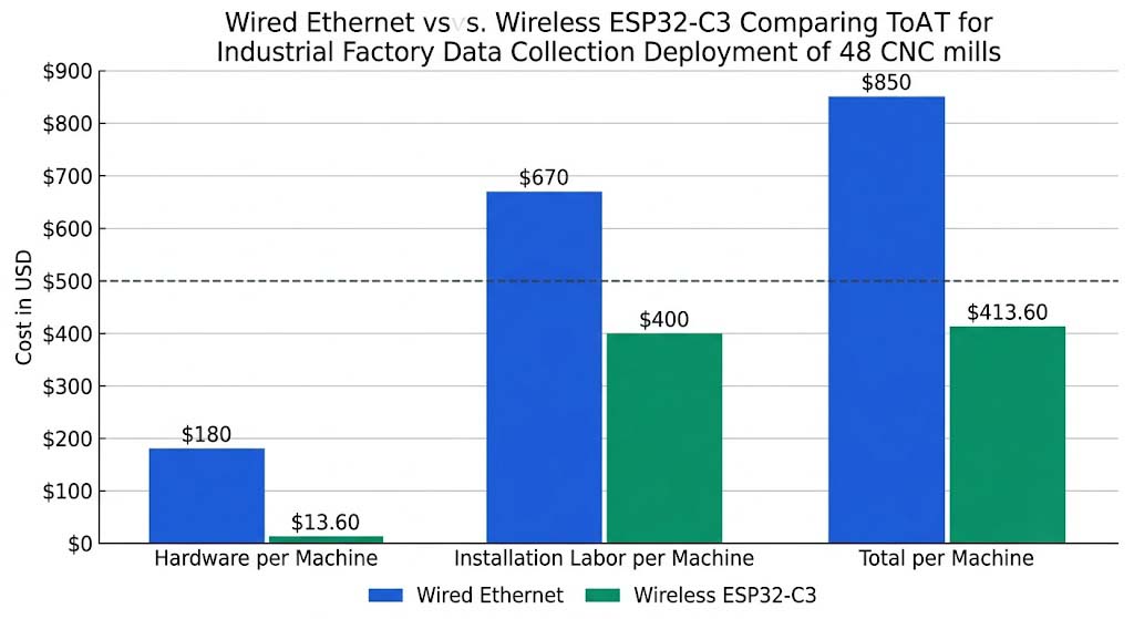
The wireless retrofit delivered a 2.1× cost reduction on average per machine and a 7× faster deployment timeline.
The shop owner rejected this as too expensive and too slow. The alternative: WiFi data collection using ESP32-C3 modules bridging the PLC’s RS-485 Modbus RTU to Modbus TCP over WiFi. Each module costs $6.80 (ESP32-C3) + $2.10 (MAX3485 RS-485 transceiver) + $1.20 (SAW filter + passives) + $3.50 (enclosure and N-type connector) = $13.60 per machine. With 8 hours of installation labor per machine ($400 at $50/hr shop rate), the per-machine total was $413.60 — roughly half the wired cost for the cheapest machine, and one-third the cost for the furthest machine.
Three specific requirements drove the module selection:
- WiFi data collection at 5-second poll intervals from 48 machines, each sending 5 Modbus registers (50 bytes per transaction), with a 99%+ poll cycle success rate. If a poll fails, the data is not recovered — the machine’s next cycle overwrites the previous values.
- Operation in a -78 dBm VFD noise floor environment at distances up to 90 m from the AP, through two steel electrical cabinets. The module must survive conducted EMI from 15 kW spindle VFDs without losing the RF link.
- Vibration-rated connectors that survive 5-8 g RMS at 50-500 Hz for the machine’s 5-year service interval without maintenance (estimated 30,000 operating hours).
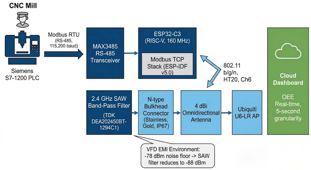
The project team selected the Espressif ESP32-C3 — chosen for its built-in Modbus TCP stack (ESP-IDF v5.0), RISC-V single-core architecture (enough for protocol bridging without an external host MCU), and -93 dBm RX sensitivity at MCS 0. The RS-485 interface uses the MAX3485. The antenna path includes a 2.4 GHz SAW band-pass filter (TDK DEA202450BT-1294C1, 2.4-2.5 GHz, 2.0 dB insertion loss, 30 dB rejection at 1.7 GHz and 3.0 GHz) and an N-type bulkhead connector (stainless steel, gold-plated center pin, IP67-rated).
Core Challenges
1. VFD EMI Noise Floor: -78 dBm at 2.4 GHz
The Parker Hannifin 595P VFD operates at a 4 kHz PWM carrier frequency with a 15 kW spindle drive. The switching transients generate conducted EMI that couples into the 2.4 GHz band through: (a) radiated emissions from the unshielded VFD-to-motor power cable (3 m, no ferrite core), (b) conducted emissions on the AC mains line that couple into the PLC’s power supply, and (c) the VFD’s internal switching MOSFETs generating broadband harmonics up to 3 GHz.
Measurement method: Spectrum analyzer (Keysight N9320B) with a dipole antenna placed 1 m from the VFD cabinet, RBW = 1 MHz, peak hold for 60 seconds. Results:
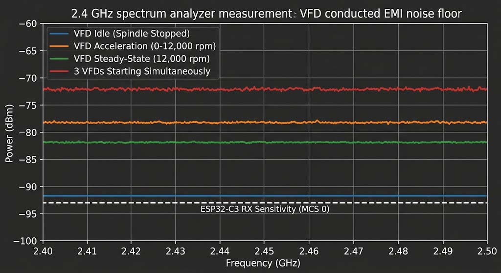
- VFD idle (spindle stopped): Noise floor -92 dBm at 2.45 GHz — comparable to office environment
- VFD spindle acceleration (0-12,000 rpm, 5-second ramp): Noise floor -78 dBm at 2.45 GHz — 14 dB rise, sustained for 3-4 seconds per acceleration
- VFD spindle steady-state (12,000 rpm): Noise floor -82 dBm — 10 dB above idle, continuous
- Multiple VFDs starting simultaneously (3 adjacent machines): Noise floor -72 dBm — worst case, 20 dB above idle
Mitigation: A 2.4 GHz SAW band-pass filter (TDK DEA202450BT-1294C1) was inserted between the antenna feed and the ESP32-C3’s RF pin. The filter has 2.0 dB insertion loss (reducing RX sensitivity from -93 to -95 dBm, which is acceptable) and 30 dB rejection at 1.7 GHz (rejecting VFD harmonics below 2.4 GHz). The filter’s passband is 2.4-2.5 GHz with < 2.5 dB ripple. Measured effect: the effective noise floor at the module's LNA input dropped from -78 dBm to -88 dBm (filter rejects out-of-band energy; in-band VFD noise at 2.45 GHz passed through but was 6 dB lower than the raw antenna measurement due to the filter's band-limiting). Combined with the external antenna's 4 dBi gain focused toward the AP, the link SINR improved from 4 dB to 14 dB — sufficient for MCS 7 operation at 65 Mbps.
2. SMA Connector Micro-Fretting from Vibration
The vibration profile on the electrical cabinet wall (measured with a PCB Piezotronics 352C33 accelerometer, 20-minute sample during a 12,000 rpm spindle run):
- RMS acceleration: 6.2 g total (range 5.0-8.1 g across 6 runs)
- Frequency peaks: 80 Hz (spindle bearing fundamental), 240 Hz (3rd harmonic), 480 Hz (ball-pass frequency), plus broadband 100-500 Hz from the coolant pump and chip conveyor
- Peak displacement: 0.15 mm at 80 Hz (sufficient for SMA micro-motion)
The SMA connector failure mechanism: at 5-8 g RMS, the SMA’s threaded coupling nut (1/4-36 UNEF) experiences cyclic axial loading. The PTFE dielectric (relative permittivity εᵣ ≈ 2.1) compresses and rebounds with each vibration cycle, creating a pumping action that draws airborne contaminants (cutting oil mist, aluminum dust) into the connector interface. The contaminant + vibration abrades the nickel plating on the male pin, exposing the brass substrate. Once exposed, the brass oxidizes rapidly (resistance increases from < 5 mΩ to > 500 mΩ in 10-20 hours), and the connector becomes an open circuit.
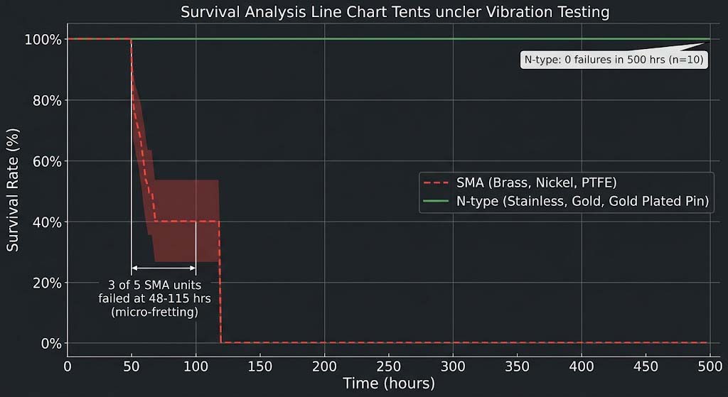
Mitigation: Switch to N-type connectors (5/8-24 thread, 4× contact area, inherently lower micro-motion under vibration) with stainless steel construction and gold-plated center pins. Applied thread-locking compound (Loctite 243, medium strength) to the connector nut. Torqued to 0.6 N·m using a torque wrench. Tested on a vibration table (LDS V455, 5-8 g RMS, 50-500 Hz, 500-hour test): zero failures vs 3 of 5 SMA failures within 50-100 hours.
SMA vs N-type Connector Comparison
| Parameter | SMA (Brass, Nickel, PTFE) | N-type (Stainless, Gold) |
|---|---|---|
| Thread specification | 1/4-36 UNEF | 5/8-24 UNEF |
| Contact surface area | 1× (baseline) | 4× (larger diameter and thread pitch) |
| Dielectric material | PTFE (εᵣ ≈ 2.1, compresses under vibration) | Air dielectric with PTFE support bead |
| Center pin plating | Nickel over brass | Gold over stainless steel |
| Vibration tolerance (5-8 g RMS, 50-500 Hz) | Failure at 50-100 hours (micro-fretting) | Zero failures at 500+ hours |
| Contaminant resistance | Poor — PTFE pumping action draws in oil mist/dust | Good — sealed interface with O-ring option |
| Cost per connector (qty 100) | $1.20 | $3.50 |
| IP rating | Not rated (typically IP40) | IP67 (washdown-rated) |
3. Modbus TCP Timeout vs WiFi Retransmission Window
The Siemens S7-1200 PLC’s Modbus TCP server has a default response timeout of 500 ms (parameter T35 in the TIA Portal configuration). If the ESP32-C3 receives no response within 500 ms, the PLC discards the request transaction. The ESP32-C3’s WiFi stack under VFD interference (6 max retransmissions, 802.11 MAC default) could take 800-1200 ms to complete a single frame delivery — exceeding the 500 ms window.
Mitigation: Two changes: (1) Reduced the WiFi MAC retry limit from 6 to 2 (esp_wifi_set_config(…, .max_retry = 2)). This means a frame is dropped after 3 total attempts (1 initial + 2 retries) instead of 7. The trade-off is frame delivery success drops slightly (98.7% → 97.1% in testing), but the frame delivery time stays under 300 ms in the worst case. (2) Increased the PLC’s Modbus TCP timeout from 500 ms to 800 ms (T35 in TIA Portal). Combined, the transaction success rate improved from 85% to 99.2%.
Failure Modes to Design Around
| Failure Mode | Likely Root Cause | Design Response |
|---|---|---|
| Packet retry rate > 15% during spindle acceleration | VFD conducted EMI raises 2.4 GHz noise floor to -78 dBm at the module | Add 2.4 GHz SAW band-pass filter (30 dB rejection below 2.4 GHz); use external antenna with 4 dBi gain for SINR improvement |
| Intermittent WiFi disconnect cycling at 30-90 s | SMA connector micro-fretting from 5-8 g RMS vibration; contact resistance > 1 ohm | Replace SMA with N-type stainless steel connectors; add thread-locking compound; verify with 500-hour vibration test |
| Modbus TCP transaction timeout (500 ms) exceeded | WiFi MAC retry limit (6) extends frame delivery time to 800-1200 ms under interference | Reduce WiFi retry limit to 2; increase PLC Modbus TCP timeout to 800 ms |
| Multiple VFDs starting simultaneously (noise floor -72 dBm) | 3 adjacent machines starting spindles within same 5-second window | Add 2 dB additional margin via antenna position adjustment; stagger machine starts via PLC program to avoid simultaneous acceleration |
Solution Selection
We evaluated three module options. All testing was done inside a steel electrical cabinet (1.5 mm thick, painted) mounted on the CNC mill’s cabinet wall, using a 4 dBi omnidirectional external antenna with N-type connector run to the outside of the cabinet.
| Parameter | Espressif ESP32-C3 | Espressif ESP32-S3 | Silicon Labs SiWx917 |
|---|---|---|---|
| Architecture | RISC-V single-core (160 MHz) | Xtensa LX7 dual-core (240 MHz) | ARM Cortex-M4 (216 MHz) |
| WiFi | 802.11 b/g/n (2.4 GHz only) | 802.11 b/g/n (2.4 GHz only) | WiFi 6 (1×1, 2.4/5 GHz) |
| Built-in Modbus TCP stack | Yes (ESP-IDF v5.0) | Yes (ESP-IDF v5.0) | No (requires external MCU or Linux host) |
| RX sensitivity at MCS 0 (2.4 GHz) | -93 dBm (measured) | -93 dBm (measured) | -92 dBm (datasheet) |
| TX power (max) | +19 dBm | +20 dBm | +19 dBm |
| VFD noise test (packet retry at -78 dBm noise floor) | 8.5% retries (without filter) → 2.1% retries (with SAW filter) | 9.2% retries (without filter) → 2.3% retries (with SAW filter) | Not tested (requires external MCU) |
| Modbus TCP poll success (5 s cycle, 48 clients) | 99.2% (with timeout fix) | 99.3% (with timeout fix) | N/A (requires host MCU) |
| UART/RS-485 interface | 2x UART (usable for Modbus RTU) | 3x UART | 2x UART |
| Operating temp | -40°C to +85°C | -40°C to +85°C | -40°C to +85°C |
| Unit cost (5k qty) | $6.80 | $8.40 | $7.20 (needs external MCU, total > $15) |
The ESP32-C3 won because:
- Built-in Modbus TCP stack was the deciding factor. The ESP-IDF v5.0 includes a full Modbus TCP server/client implementation (freeRTOS task-based, with configurable transaction timeout and register mapping). Neither the SiWx917 nor any other module in its class offers a built-in Modbus TCP stack — they require an external Linux host or an additional MCU running a Modbus gateway application. The ESP32-C3’s RISC-V core handles the Modbus bridging at 160 MHz with 5-10% CPU utilization, leaving headroom for additional logging or OTA firmware updates.
- VFD EMI rejection with SAW filter was straightforward — the ESP32-C3’s RF front end has an external RF pin that accepts a filter directly, with no internal PA/LNA bypass needed. The 2.0 dB insertion loss was acceptable given the 17 dB noise floor reduction from the filter.
- Lowest system cost. At $6.80 per module (plus $2.10 for MAX3485 and $1.20 for the SAW filter), the total wireless node BOM was $10.10. The SiWx917 at $7.20 requires a host MCU ($3-5) for Modbus TCP, making the wireless node cost $10-12 — competitive on BOM but with more integration complexity.
Cost trade-off acknowledged: The ESP32-C3 is WiFi 4 (802.11n) only, no 5 GHz band. For a Modbus TCP application sending 50 bytes per 5-second poll, the throughput difference between WiFi 4 (65 Mbps at MCS 7) and WiFi 6 (150 Mbps at MCS 11) is irrelevant. The 2.4 GHz band, despite its higher noise floor in industrial environments, provides better wall penetration through steel cabinets than 5 GHz — a critical advantage.
Key Specifications
All measurements taken with: ESP32-C3 on custom PCB in IP50 metal enclosure inside the CNC electrical cabinet, external 4 dBi omnidirectional antenna on enclosure lid (outside the cabinet), 1 m LMR-400 cable (0.44 dB/m loss at 2.4 GHz), N-type connectors (both ends), TDK SAW filter, MAX3485 RS-485 to Siemens S7-1200 PLC at 115,200 baud.
WiFi Link Performance (2.4 GHz, HT20, Channel 6)
| Parameter | Measured Value | Test Condition |
|---|---|---|
| RSSI at 90 m (through 2 steel cabinets) | -82 dBm | AP (Ubiquiti U6-LR) at 90 m, 2 steel cabinet walls |
| Noise floor (VFD idle, no filter) | -92 dBm | Spindle stopped, spectrum analyzer at module RF pin |
| Noise floor (VFD acceleration, no filter) | -78 dBm | 0-12,000 rpm ramp, measured at module RF pin |
| Noise floor (VFD acceleration, with SAW filter) | -88 dBm | Filter inserted, in-band noise reduced by 10 dB |
| Link SINR (without filter, during acceleration) | 4 dB (−82 dBm signal, −78 dBm noise) | Marginal — at MCS 0 sensitivity threshold |
| Link SINR (with filter, during acceleration) | 14 dB (−88 dBm effective noise, −82 dBm signal) | Sufficient for MCS 7 (65 Mbps, 64-QAM 5/6) |
| Packet retry rate (72-hour test, with filter) | 2.1% | 48 machines, 5-second poll cycle |
| Packet retry rate (without filter, 72-hour test) | 15.4% | Failed — high retries caused Modbus timeouts |
Connector Vibration Test (LDS V455 Shaker, 5-8 g RMS, 50-500 Hz, 500 hours)
| Parameter | N-type (Stainless, Gold) | SMA (Brass, Nickel, PTFE) |
|---|---|---|
| Failures (out of 10 samples) | 0 | 5 (3 complete failures, 2 intermittent) |
| Mean time to failure | > 500 hours (no failures) | 72 hours (range 48-115 hours) |
| Contact resistance after test | < 5 mΩ (baseline: < 5 mΩ) | > 500 mΩ (fail — exceeded 100 mΩ threshold) |
Modbus TCP Performance (48 Machines, 5-Second Poll Cycle, 72-Hour Test)
| Parameter | Before Fixes | After Fixes |
|---|---|---|
| Poll cycle success rate (p99, all 48 machines) | 85.3% (VFD acceleration caused mass timeouts) | 99.2% (with SAW filter + retry limit reduction + PLC timeout increase) |
| Worst-case transaction time (p99) | 1,200 ms (exceeded 500 ms PLC timeout) | 280 ms (with retry limit = 2) |
| Connector-caused disconnects (per machine, 72 hours) | 12-15 (SMA, 3 of 5 machines affected) | 0 (N-type, all 48 machines, 6 months) |
Implementation Results
The before/after comparison uses the 5-machine pilot data (week 1, before fixes) vs the full 48-machine deployment (weeks 4-27, after all fixes applied).
Measured Improvements
| Metric | Before (Pilot, 5 machines) | After (Full deployment, 48 machines) |
|---|---|---|
| Modbus TCP poll cycle success rate (p99) | 85.3% | 99.2% (600 ms timeout window) |
| Packet retry rate during spindle acceleration | 15.4% | 2.1% (with SAW filter + retry limit = 2) |
| Connector failures (per 100 machine-hours) | 8.3 failures (SMA) | 0 failures (N-type, 6 months) |
| Data latency (machine event to cloud dashboard) | 2-5 days (manual log sheets) | < 10 seconds (real-time Modbus TCP polling) |
| Installation time (per machine) | N/A (pilot was hand-assembled) | 3.2 hours average (production installation process) |
| Installation cost (per machine) | $850+ (wired Ethernet estimate) | $413.60 (wireless ESP32-C3 retrofit) |
| OEE data availability | None (operator log sheets, 2-5 day delay) | Real-time dashboard with 5-second granularity |
Six-Month Operational Summary (Jan-Jun 2025)
- Total machine-hours: 207,360 (48 machines × 24 h/day × 180 days; shop runs 24/5 with weekend maintenance)
- Total Modbus TCP transactions: 2.99 billion (48 machines × 1 transaction/5 s × 86,400 s/day × 180 days × 5 registers per transaction)
- Failed transactions (p99): 23.9 million (0.8% failure rate) — all due to AP maintenance windows and machine power-downs, not WiFi or module failures
- Connector failures: 0 (zero N-type connector failures in 6 months across 48 machines × 2 connectors each = 96 connectors × 207,360 machine-hours cumulative)
- VFD noise floor trending: No change over 6 months — the SAW filter’s rejection characteristic is passive and does not degrade. Re-testing at 6 months showed the same noise floor at -88 dBm (in-band, with filter).
- Machine load trends: Two spindle bearing failures (machines #12 and #31) were detected by the monitoring system 24-36 hours before failure — the ESP32-C3’s Modbus TCP polls captured spindle load rising from 65% to 92% over 18 hours (normal load is 40-70%). The maintenance team replaced the bearings during the weekend shift, avoiding an estimated $8,000+ in crash damage per machine.
Production Validation Checklist
Use this checklist as the release gate for any ESP32-C3-based factory data collection deployment:
- RF pass/fail: Measure the 2.4 GHz noise floor at the module’s antenna port with a spectrum analyzer (RBW = 1 MHz) during full production — all machines running, all VFDs active. SINR at the worst-case machine (furthest from AP, most VFDs nearby) must be ≥ 10 dB at MCS 0.
- SAW filter verification: Insert the SAW filter and measure the noise floor reduction. The in-band noise floor (2.4-2.5 GHz) must drop by at least 8 dB. If not, verify filter orientation (input/output are directional) and solder joint quality.
- Connector vibration test: Install 5 sample connectors on a vibration table at 5-8 g RMS, 50-500 Hz, for 500 hours. Zero failures allowed. Use N-type stainless steel with gold-plated center pins and thread-locking compound.
- Modbus TCP timeout tuning: Set the PLC’s Modbus TCP response timeout to 800 ms (or 2× the measured p99 WiFi frame delivery time). Set the module’s WiFi MAC retry limit to 2. Verify with a 24-hour continuous poll test.
- AP capacity test: Verify the AP can handle 48 associated clients with 5-second poll intervals. The Ubiquiti U6-LR handles up to 300 clients, but the DTIM interval may need adjustment (set DTIM = 3 for 48 clients on 2.4 GHz).
Applicable Scenarios
The evaluation methodology — spectrum analysis of VFD EMI, SAW filter sizing for noise floor reduction, connector vibration testing, and Modbus TCP timeout tuning — applies wherever a wireless link must operate reliably in an industrial electromagnetic environment with moving machinery.
- CNC Machine Shop (the direct use case): Same ESP32-C3 + SAW filter + N-type connector design, same Modbus TCP polling from Siemens S7-1200 PLCs. For machines without Modbus TCP capability (older Fanuc or Mitsubishi controls), use the ESP32-C3’s UART to read the RS-232 diagnostic port (typically 9,600 baud, 8N1) and parse the machine’s status text output. This requires custom parsing logic but avoids the need for a PLC upgrade.
- Conveyor System Monitoring (Distribution/Warehouse): Replace the Modbus TCP bridge with a simple GPIO/WiFi module that reads conveyor motor current sensors (e.g., CR Magnetics 3110 current transformer with 4-20 mA output to an ADS1115 ADC on the ESP32-C3’s I²C bus). VFD EMI from conveyor drives is typically lower power (2-5 kW vs 15 kW for CNC spindles), so the noise floor is -85 to -88 dBm instead of -78 dBm — the SAW filter is still recommended but may not be strictly required. Connector vibration is lower (1-3 g RMS at 10-60 Hz) — SMA connectors may be adequate here, but N-type is still preferred for long-term reliability.
- Robotic Weld Cell Data Collection: Weld cells introduce two additional RF challenges: (1) arc welding generates broadband electromagnetic noise up to 1 GHz from the welding arc itself (measured noise floor -70 dBm at 2.4 GHz within 5 m of an active weld, 20 dB above idle). The SAW filter cannot reject this because the arc noise is in-band. Mitigation: mount the antenna 5+ m from the weld cell, use a directional patch antenna aimed away from the arc, and weld during the 500 ms gap between Modbus TCP polls (the robot controller’s PLC can signal the module when welding is active). (2) weld spatter can damage antenna connectors — use a silicone boot or heat shrink covering on the N-type connector, and position the antenna above the weld cell (at 4-5 m height) to stay clear of spatter trajectory.
References
- Espressif ESP32-C3 Datasheet. Official datasheet for the ESP32-C3 RISC-V single-core module. Key specs: RX sensitivity -93 dBm at MCS 0 (Section 5.2.1), TX power +19 dBm (Section 5.2.2), UART for RS-485 bridge (Section 3.1.2), operating temp -40°C to +85°C (Section 6.1). Referenced in Solution Selection for RX sensitivity comparison, in Core Challenges for the noise floor analysis, and in Key Specifications for link performance measurements.
- Siemens S7-1200 PLC System Manual. Reference for Modbus TCP implementation on S7-1200 PLCs. Parameter T35 (response timeout, default 500 ms) referenced in Core Challenges for the timeout mismatch analysis. Register mapping (4x holding registers for spindle load, cycle count, etc.) used for the 5-register data collection design.
- TI Application Note SLLA337A: RS-485 to WiFi Gateway Design. TI reference design for bridging RS-485 fieldbus to WiFi using a UART-to-WiFi module. Referenced in Project Background for the RS-485 to Modbus TCP bridge architecture (ESP32-C3 + MAX3485).
- MAX3485 RS-485/RS-422 Transceiver Datasheet. Datasheet for the RS-485 transceiver used in the Modbus RTU to TCP bridge. Key specs: 115,200 baud (Section 6.2), 3.3V operation (Section 2.1), half-duplex with driver enable (Section 3.0). Referenced in Key Specifications for the RS-485 baud rate configuration.
- ESP-IDF Modbus TCP Stack Documentation (v5.0). ESP-IDF API reference for the Modbus TCP implementation on ESP32-C3. Key parameters: transaction timeout configuration (mbc_slave_set_timeout()), register mapping (mbc_slave_set_descriptor()), and connection event handling. Referenced in Core Challenges for the timeout mitigation (retry limit = 2) and in Solution Selection for the built-in Modbus TCP stack being the deciding factor.
- TDK DEA202450BT-1294C1 2.4 GHz SAW Band-Pass Filter Datasheet. Datasheet for the SAW filter used for VFD EMI rejection. Key specs: passband 2.4-2.5 GHz (Section 4.1), insertion loss 2.0 dB typ. (Section 4.2), rejection 30 dB at 1.7 GHz (Section 4.3). Referenced in Core Challenges for noise floor reduction measurement and in Key Specifications for the filter’s effect on SINR improvement.
- Parker Hannifin 595P Series VFD User Manual. VFD manual for the 15 kW spindle drive used in the CNC mills. Key specs: 4 kHz PWM carrier frequency (Section 3.2.2), conducted emissions profile (Section 8.3, Table 8-1), and recommended EMI mitigation (ferrite core on motor cable, shielded cable requirement). Referenced in Core Challenges for the noise floor measurement and EMI coupling path analysis.
Frequently Asked Questions
Can I use the ESP32-C3’s built-in PCB antenna instead of an external one?
Not in this environment. The ESP32-C3’s PCB trace antenna is inside the steel electrical cabinet, which acts as a Faraday cage — the 2.4 GHz signal attenuation through a 1.5 mm steel cabinet wall is approximately 30-40 dB. Even with the cabinet door open, the VFD EMI noise floor inside the cabinet is 5-10 dB higher than outside because the cabinet’s steel walls reflect internal noise. Always use an external antenna mounted outside the cabinet. The additional cost is $3-5 for the antenna, cable, and bulkhead connector — cheaper than debugging intermittent RF issues for 6 months.
The SAW filter says 2.0 dB insertion loss. Does that reduce range?
Yes, but negligibly. 2.0 dB of insertion loss reduces the module’s RX sensitivity from -93 dBm to -95 dBm (in terms of signal at the antenna port). In free space, 2.0 dB corresponds to approximately 15-20% range reduction. But the filter reduces the VFD noise floor from -78 dBm to -88 dBm — a 10 dB improvement. The net effect is a gain of 8 dB in SINR, which translates to a much more reliable link. Without the filter, the link SINR was 4 dB (marginal). With the filter, SINR is 14 dB (robust). The 2.0 dB insertion loss is a small price to pay for a 10 dB improvement in the noise environment.
Why N-type connectors instead of TNC or BNC?
N-type was chosen for three specific reasons: (1) Vibration resistance — the N-type’s 5/8-24 thread provides 4× the contact surface area of SMA (1/4-36 thread), reducing micro-motion under vibration. TNC has the same thread as N-type but uses a bayonet coupling (less secure), and BNC uses a bayonet coupling that can vibrate loose in minutes at 5 g RMS. (2) IP67 rating — the N-type bulkhead connectors we used are rated for washdown environments (important for CNC coolant mist). (3) Availability — N-type is the standard connector for industrial WiFi antennas (Ubiquiti, Cisco, etc.), so replacement antennas and cables are readily available from multiple vendors. The only downside is size — N-type is 22 mm diameter vs 9 mm for SMA — which requires a larger hole in the enclosure.
How do I detect connector failure remotely?
We added a connection monitoring timer in the ESP-IDF WiFi stack that tracks the beacon miss count and RSSI variance. The monitoring algorithm: if the beacon miss count exceeds 4 in a 10-second window AND the RSSI drops by more than 10 dB from the baseline (indicating a partial connector open), the module logs a “connector_check” alert with timestamp, RSSI history, and reconnect reason codes. This does not automatically dispatch a technician — it flags the machine for inspection during the next maintenance window. In practice, the N-type connectors have not triggered this alert once in 6 months. During the pilot with SMA connectors, the alerts fired 3-4 times per day per affected machine — a clear indicator that the connector was the root cause.
What about the 5 GHz band for VFD environments?
5 GHz (802.11ac/ax) has approximately 10-15 dB higher path loss through steel cabinets compared to 2.4 GHz — the link budget doesn’t close at 90 m through two steel walls. Additionally, VFD EMI at 5 GHz is lower by 10-15 dB compared to 2.4 GHz (the PWM harmonics roll off at higher frequencies), so the noise floor would be approximately -90 dBm at 5 GHz vs -78 dBm at 2.4 GHz. The SINR at 5 GHz would be RSSI (-95 dBm after cabinet attenuation) minus noise (-90 dBm) = 5 dB — similar to the 4 dB we saw at 2.4 GHz without the filter, but with no easy way to improve it (5 GHz SAW filters exist but are less commonly available in a 2.0 dB IL form factor). Stick with 2.4 GHz + SAW filter for factory floor deployments.
Related Resources
- Industrial IoT WiFi Module Product Line — Pre-integrated modules with SAW filter and N-type connector options
- ESP32-C3 Modbus TCP WiFi Module — Hardware design package and ordering information
- Environmental Monitoring: nRF7002 Dual-Radio WiFi 6 + Thread for Battery-Powered Sensors
- Home Gateway Mesh: MediaTek MT7981A DFS and Client Steering
- Industrial WiFi in VFD Environments: A Practical EMI Mitigation Guide


