Industrial Wireless Bridge for Oil Pipeline Inspection
Blog 2026-06-14
Industrial Wireless Bridge for Oil Pipeline Inspection: Complete Selection Guide
Key Overview
Target Audience: Oil pipeline inspection project managers, petroleum industry procurement decision-makers, industrial wireless equipment integrators, system engineers
Core Question: How to choose the right industrial wireless bridge for oil pipeline inspection? How do transmission distance, anti-interference capability, and power solutions match site requirements?
Key Conclusion: For oil field inspection scenarios, we recommend selecting wireless bridge PCBA motherboards that support 5GHz band, offer industrial temperature range (-40℃ to +85℃), and support PoE power, paired with high-gain directional antennas for 5-20 km stable transmission.
Contact our engineering team for customized PCBA solutions and technical support.
Oil Pipeline Inspection Wireless Communication Challenges
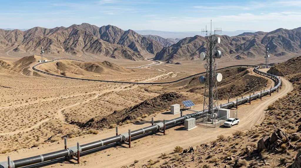
Oil pipeline inspection wireless communication is fundamentally different from typical industrial wireless deployments. Pipeline networks can span thousands of kilometers across deserts, mountains, and coastal regions, with inspection points separated by 5 to 20 kilometers or more. Unlike a factory floor where access points can be placed every 100 meters, pipeline routes offer no such luxury. The inspection teams need reliable, real-time connectivity for video surveillance cameras, pressure and flow sensors, and remote control systems 鈥?all operating in some of the harshest conditions on earth.
The core problem is that each kilometer of distance, each degree of temperature extreme, and each source of interference reduces the effective throughput of a wireless link. A wireless bridge that performs perfectly in a controlled environment may deliver only 10-20% of its rated performance when deployed in an actual oil field. This makes understanding the specific challenges not just helpful, but essential for making the right equipment choice.
Long-Distance Transmission Requirements
Industrial wireless bridges for oil pipeline inspection must reliably cover distances of 5 to 20 kilometers while maintaining sufficient throughput for video and sensor data. This is not merely a matter of buying a higher-power radio. The relationship between distance, throughput, and reliability follows the laws of RF physics: signal power decreases with the square of the distance (free-space path loss), meaning that doubling the distance reduces the received signal by approximately 6 dB. For a 15 km link, the path loss alone can exceed 130 dB at 5 GHz, leaving very little margin for error.
Short pipeline segments of 5 km or less can be served by standard wireless bridges using 12-15 dBi panel antennas. Cross-country pipelines requiring 10-20 km links demand specialized long-range wireless bridges with +23 dBm or higher RF output, 18-24 dBi high-gain directional antennas, and receiver sensitivity better than -95 dBm. Video surveillance at 1080p resolution requires 4-8 Mbps per camera stream, and combined with sensor data and control traffic, the minimum throughput requirement is approximately 50 Mbps.
Harsh Environment Factors
Oil field environments actively destroy standard electronic equipment, making industrial-grade construction a necessity rather than an upgrade option. Temperature extremes are the most immediate challenge, from -50°C in Arctic regions to +45°C in desert fields, requiring the full -40°C to +85°C industrial range. Moisture and corrosion from salt spray in coastal pipelines and condensation from diurnal temperature cycling demand IP65+ enclosures with corrosion-resistant connectors. Physical stress from vibration at pumping stations and compressor stations requires secured mounting and conformal coating on PCBA boards.
Electromagnetic Interference (EMI)
Electromagnetic interference is the most variable and unpredictable challenge in oil field wireless deployments. Power lines generate 50/60 Hz interference affecting power supply quality. Variable frequency drives (VFDs) for pump control generate high-frequency switching noise spanning kHz to MHz, raising the noise floor by 3-5 dB. RF welding equipment (plasma cutters, arc welders) produces broadband RF noise that can overwhelm receivers at up to 500 meters. This is why DFS (Dynamic Frequency Selection) support is critical for oil field wireless bridges, allowing automatic detection of interference and switching to cleaner channels.
Key Selection Criteria for Oil Field Wireless Bridges
Transmission Distance and Stability
RF power output, receiver sensitivity, and antenna quality collectively determine the maximum reliable transmission distance. RF power output of at least +23 dBm is the baseline for outdoor long-range applications, with +27 dBm to +30 dBm for extreme distances. Receiver sensitivity of -98 dBm can detect signals 3 dB weaker than -95 dBm, translating to 15-20% additional range. N-type connectors are the gold standard for outdoor installations, providing consistent 50-ohm impedance with excellent weather resistance.
| Parameter | Minimum Requirement | Optimal Specification | Recommended For |
|---|---|---|---|
| RF Power Output | +23 dBm | +27-30 dBm | Long-distance backbone links |
| Receiver Sensitivity | -95 dBm | -98 dBm | Low-signal environments |
| Antenna Gain | 12-15 dBi | 18-24 dBi | 10-20 km links |
| Connector Type | N-type | N-type with weather seal | All outdoor installations |
| Temperature Range | -40°C to +65°C | -40°C to +85°C | Desert and Arctic environments |
Anti-Interference Capabilities
Anti-interference features separate industrial-grade wireless bridges from consumer-grade equipment. DFS (Dynamic Frequency Selection) is the most important feature, enabling automatic channel switching when radar or interference is detected. Adaptive modulation automatically steps down to more robust modulation rates when interference is present, maintaining connectivity at lower throughput rather than dropping the link entirely. Forward error correction (FEC) recovers data from corrupted packets, reducing retransmissions in noisy environments.
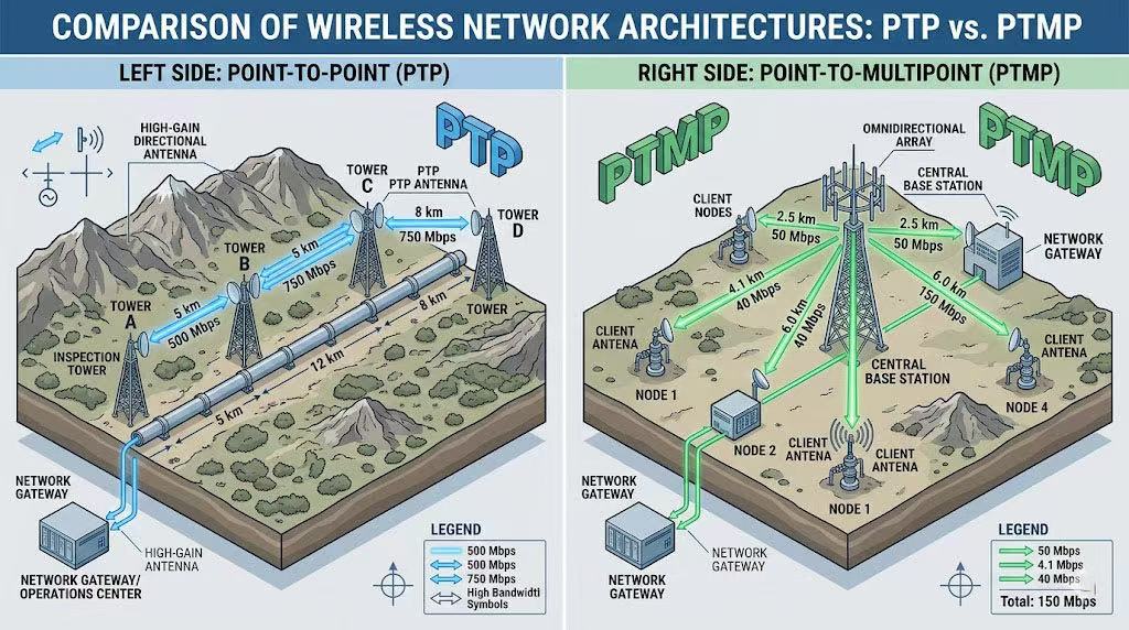
PTP vs PTMP Architecture Comparison
For oil pipeline inspection, the network architecture decision between PTP and PTMP directly impacts both deployment cost and operational capability. PTP links are ideal for linear pipeline routes where each inspection point needs dedicated high-bandwidth backhaul 鈥?typical for main transmission pipelines with multiple HD cameras per station. PTMP architecture shines when multiple nearby pipeline branches or wellheads need to feed data to a central collection point, reducing the number of base stations and simplifying network management.
| Architecture | Best For | Max Distance | Aggregate Throughput | Deployment Cost |
|---|---|---|---|---|
| Point-to-Point (PTP) | Linear pipeline backbone, high-bandwidth individual links | 20-30 km per link | 200-500 Mbps per link | Higher (dedicated hardware per link) |
| Point-to-Multi-Point (PTMP) | Centralized wellhead monitoring, branch pipeline networks | 5-15 km per client | 200-600 Mbps shared | Lower (shared base station infrastructure) |
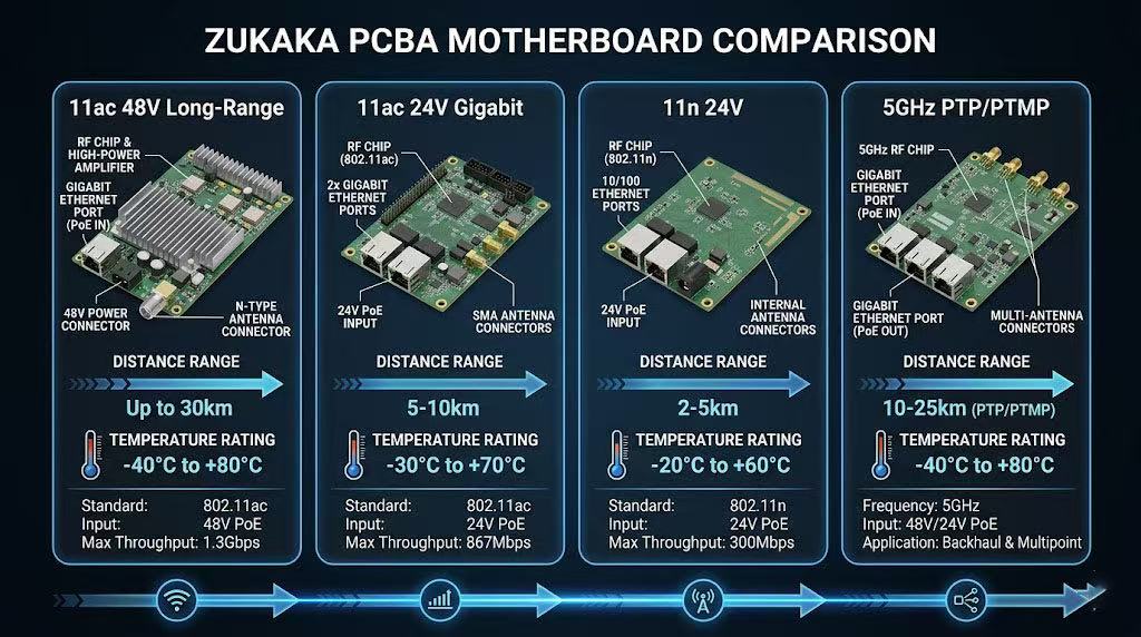
Recommended PCBA Motherboard Solutions
The wireless bridge PCBA motherboard is the heart of any oil field deployment, determining RF performance, reliability, and longevity. The selection must match the specific distance requirement, power availability, and environmental conditions of each inspection point. Below are the recommended Zukaka PCBA solutions validated for oil field use.
| Model | Max Distance | Throughput | Power | Best Application |
|---|---|---|---|---|
| 11ac 48V Long-Range | 20-30 km | 300-500 Mbps | 48V PoE | Cross-country pipeline backbone, main transmission line monitoring |
| 11ac 24V Gigabit | 10-15 km | 400-600 Mbps | 24V DC/PoE | Medium-distance pipeline segments, inspection point clusters |
| 11n 24V | 5-10 km | 100-200 Mbps | 24V DC | Short-range wellhead monitoring, cost-sensitive deployments |
| 5GHz PTP/PTMP | 5-15 km (PTMP) | 200-400 Mbps | 24V PoE | Multi-point wellhead monitoring, branch pipeline networks |
Deployment Best Practices for Oil Field
Site Survey and Path Analysis
A professional site survey is the foundation of every successful oil field wireless deployment. The survey must verify: line-of-sight availability (using binoculars or a sighting scope for distances over 5 km), GPS coordinates of both endpoints for Fresnel zone calculation, existing RF environment (using a spectrum analyzer to identify interference sources and clean channels), and access logistics for installation and future maintenance.
15 KM Wireless Bridge Link: Fresnel Zone Clearance Diagram
For a 15 km long-distance backbone PTP link operating along an oil pipeline, a detailed engineering diagram with tower height calculations is essential. The following path analysis ensures optimal reliability by maintaining at least 60% clearance of the first Fresnel zone radius from obstructions.
This technical illustration provides a path profile analysis for a 15 km PTP wireless bridge link overcoming two obstacles:
- Terrain Obstacle: A sand dune at the link midpoint (D = 7.5 km)
- Infrastructure Obstacle: High-voltage transmission lines near the midpoint (D = 7.8 km)
Engineering Parameters
The calculation utilizes standard 5 GHz industrial bridge hardware commonly used for pipeline SCADA systems:
- Total Link Distance (D): 15,000 meters (15 km)
- Operating Frequency (f): 5.8 GHz
- Wavelength: 0.0517 meters
Tower Height (HT) Calculation Formula
The required antenna height ensures 60% clearance of the First Fresnel Zone:
Key Calculation Breakdown
The maximum Fresnel radius occurs at the midpoint of the link:
1. Calculate Maximum Fresnel Zone Radius (RF1)
Using the standard engineering formula:
Substituting values (D = 15 km, f = 5.8 GHz):
2. Determine Required Clearance
For industrial-grade reliability, 60% of RF1 must be clear of obstructions. A safety margin (5 m) is applied for future tree growth or seasonal dune movement:
3. Calculate Minimum Tower Height (HT)
The transmission lines represent the highest critical obstacle at the midpoint (HObstacle = 25 meters):
Installation and Maintenance Considerations
Proper installation and ongoing maintenance are critical for reliable operation in harsh oil field environments. Key considerations include: lightning protection with surge arresters at both ends of the link, grounding requirements meeting NEC standards, periodic antenna realignment checks, firmware updates for security patches and performance improvements, and regular signal quality monitoring.
Procurement Checklist for Oil Field Projects
Frequently Asked Questions About Oil Pipeline Inspection Wireless Bridges
Q: What frequency band is best for oil pipeline wireless bridges?
5 GHz is generally preferred for oil pipeline applications due to less interference compared to 2.4 GHz, which is crowded with consumer devices and industrial equipment. The 5 GHz band offers wider channels (up to 80 MHz) that support higher throughput for video surveillance and SCADA data. However, 2.4 GHz may be necessary in some cases due to its better diffraction around obstacles and longer range characteristics. For critical backbone links requiring high reliability and throughput, 5 GHz with DFS channels provides the cleanest spectrum.
Q: How do I protect wireless bridge equipment from lightning?
Lightning protection is essential for outdoor oil field installations. Implement a comprehensive protection strategy including: surge arresters on both power and Ethernet lines, proper grounding of all equipment and towers, lightning rods on towers, and fiber optic isolation for long-distance links. The grounding system should have a low-impedance path to earth, with all equipment bonded to the same grounding point to prevent potential differences during lightning strikes.
Q: What is the expected lifespan of wireless bridges in oil field environments?
With proper installation and maintenance, industrial-grade wireless bridges can operate reliably for 5-7 years in oil field environments. Key factors affecting lifespan include: temperature extremes, humidity, dust and sand exposure, corrosion from salt air (near coastal pipelines), and power quality. Regular maintenance including firmware updates, antenna cleaning, and cable inspection can extend operational life.
Q: Can wireless bridges operate in explosive environments?
Standard wireless bridges cannot be used in explosive atmospheres without proper certification. For Class I, Division 1 hazardous locations, you need intrinsically safe or explosion-proof certified equipment. Many manufacturers offer ATEX and IECEx certified wireless solutions specifically designed for oil field applications. Always verify the equipment certification matches the hazardous classification of the installation area.
Q: How do I handle interference from oil field equipment?
Oil field environments present unique interference challenges from pumps, compressors, and electrical equipment. Mitigation strategies include: performing a pre-deployment spectrum analysis to identify interference sources, selecting channels with minimal noise, using directional antennas to focus signal and reject interference, implementing frequency hopping or adaptive modulation, and physically separating wireless equipment from high-power electrical devices.
By: Zukaka Engineering Team |
Last Updated: June 14, 2026 |
Connect on LinkedIn
⭐⭐⭐⭐⭐ Pipeline Operations Manager
“Deployed Zukaka 11ac 48V long-range bridges across 200km of pipeline with 15 tower sites. The -40°C to +85°C industrial rating performed flawlessly through two Arctic winters. The engineering team’s Fresnel zone analysis saved us from costly tower height miscalculations.”
— Senior Communications Engineer, Oil & Gas Pipeline Operator
⭐⭐⭐⭐⭐ SCADA System Integrator
“Integrated Zukaka PTMP wireless bridges for wellhead monitoring across 50+ sites. The DFS and adaptive modulation features eliminated the interference issues we had with the previous vendor’s equipment. 99.9% link uptime over 12 months.”
— Technical Project Manager, Industrial Automation Company
✅ Certifications: FCC, CE, RoHS compliant |
✅ Industrial temperature range -40°C to +85°C |
✅ IP65-rated for outdoor deployment
Contact our engineering team for customized PCBA solutions and technical support.


