Outdoor Wireless AP & Base Station Solutions: Complete Deployment Guide
Key Overview
Target Audience: Network engineers, system integrators, facility managers, outdoor WiFi deployment specialists
Core Question: What is the difference between outdoor wireless APs and traditional APs? How to choose the right outdoor AP? How to deploy outdoor WiFi coverage?
Key Conclusion: Outdoor APs require higher IP ratings, stronger anti-interference capabilities, and PoE power support. Selection should consider coverage range, user density, environmental conditions, and power supply methods.
Outdoor vs Indoor Wireless AP: Key Differences
The fundamental difference between outdoor and indoor wireless APs is that outdoor APs are engineered for environmental survival first and RF performance second, while indoor APs prioritize aesthetic design and ease of installation over ruggedness. An outdoor AP must withstand: direct rain and snow ingress (sealed to IP65 or higher), extreme temperature cycling from -40°C at night to +70°C in direct sun, UV radiation that degrades plastics and seals over 3-5 years, wind loads up to 160 km/h for pole-mounted units, and corrosive environments (salt spray in coastal areas, chemical exposure in industrial facilities). Indoor APs are not designed for any of these conditions — their plastic enclosures crack under UV exposure, internal condensation destroys electronics within weeks, and temperature extremes cause oscillator drift and premature component failure.
Environmental Protection — IP Rating, Temperature, and Material Selection
| Protection Dimension | Indoor AP Specification | Outdoor AP Specification | Why It Matters | Failure Mode If Ignored |
|---|---|---|---|---|
| IP Rating (Ingress Protection) | IP30 (no dust or water protection) | IP65 (dust-tight, low-pressure water jets) or IP67 (immersion up to 1m) | Rain, sprinklers, condensation, and dust ingress are hazards in any outdoor deployment | Water in enclosure → short circuit → complete unit failure, typically within 30-90 days |
| Operating Temperature Range | 0°C to 40°C (commercial grade) | -40°C to +70°C (industrial grade) | Outdoor equipment must survive diurnal temperature swings of 40-60°C and direct solar heating of dark surfaces to 80°C+ | Oscillator drift → connection drops; capacitor failure → power supply failure; thermal shutdown in summer |
| Humidity and Condensation Resistance | 5-90% RH (non-condensing) | 0-100% RH (including condensation with conformal coating) | Coastal areas, rainy seasons, and temperature drops at night create condensation inside enclosures | PCB corrosion → intermittent faults → permanent failure; RF connector corrosion → signal degradation |
| UV and Weather Resistance | Standard ABS plastic (UV-degrades in 6-12 months outdoors) | UV-stabilized polycarbonate or ASA, stainless steel hardware, silicone gaskets | UV radiation embrittles standard plastics; wind-driven rain enters through degraded seals after 2-3 years | Cracking enclosure → water ingress; gasket failure → seal breach; faded/embrittled plastics in 18-24 months |
RF Performance Differences — Transmit Power, Antenna Options, and Interference Handling
Outdoor APs have fundamentally different RF requirements than indoor APs because they must cover longer distances, compete with higher ambient RF noise, and support external antenna systems that indoor APs cannot accommodate. Indoor APs typically integrate low-gain antennas (2-4 dBi) with transmit power limited to 17-20 dBm (50-100 mW) — sufficient for rooms and open-plan offices. Outdoor APs operate at 23-30 dBm (200-1000 mW) with support for external antennas up to 15-30 dBi, providing 100-500x the effective radiated power of an indoor AP. This higher power also requires better filtering and linearity in the RF chain to meet regulatory emission limits (FCC Part 15, ETSI EN 302 502) — outdoor APs use higher-quality SAW filters, larger heatsinks for PA cooling, and more sophisticated power management to maintain linearity at high output levels.
Outdoor APs must also handle higher levels of RF interference because outdoor environments have less RF containment than indoor spaces. In urban outdoor deployments, the 2.4GHz band is often saturated with noise from neighboring WiFi networks, Bluetooth devices, microwave ovens in nearby buildings, and radar systems. Outdoor APs need: tighter receive filtering (reducing desensitization from out-of-band signals), better coexistence algorithms (CSMA/CA with adaptive CCA thresholds), and DFS support for 5GHz operation to avoid weather radar interference. The noise floor in urban outdoor environments is typically -85 to -95 dBm (vs. -100 to -105 dBm indoors), meaning outdoor APs need 10-15 dB of additional signal-to-noise ratio margin to achieve equivalent throughput.
Installation Requirements — Mounting, Cabling, and Protection Systems
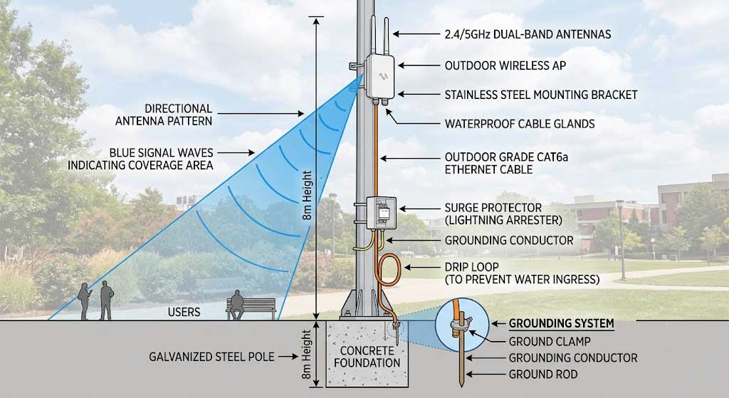
Outdoor AP installation is substantially more complex than indoor installation because it requires structural mounting, weatherproofed cabling, lightning protection, and often remote power delivery through PoE. Indoor APs typically sit on a ceiling or shelf and connect via a standard Ethernet cable — installation takes 5-10 minutes. Outdoor AP installation involves: pole or wall mounting with stainless steel hardware rated for wind loads (calculate: F = 0.5 × ρ × v² × Cd × A, where v is the maximum expected wind speed in m/s), weatherproofed Ethernet connections using outdoor-rated Cat6/6a cable with waterproof RJ45 connectors (or direct burial cable for underground runs), lightning protection at the mast (NFPA 780 compliant grounding conductor, surge protector at the building entry point, and proper earth grounding with impedance < 10Ω), and cable routing through conduit or along existing infrastructure with drip loops at entry points to prevent water ingress.
The total installed cost difference between indoor and outdoor APs is typically 3-5x, with the majority of the cost coming from installation labor, lightning protection materials, and weatherproof cabling rather than the AP hardware itself. A typical indoor AP installation costs $150-300 (hardware + 30-minute installation). A typical outdoor AP installation costs $500-1,500 depending on: mounting structure (existing pole vs new pole, roof mount vs wall mount), cable run length (50m of outdoor-rated Cat6 costs $80-120, trenching adds $15-30/m), lightning protection ($100-300 per AP), and installation labor (2-4 hours for a single AP, including grounding and sealing). For solar-powered installations in remote locations, add $800-2,000 per AP for the solar power system (panel, controller, battery, mounting).
Selection Criteria for Outdoor Wireless AP
Environmental Rating — Matching IP and Temperature Specifications to Deployment Conditions
The IP rating and temperature range of an outdoor AP must match the specific environmental conditions of the deployment site, and selecting the wrong rating is the most common cause of premature outdoor AP failure. For general outdoor use (covered areas, under eaves, in sheltered locations), IP65 is sufficient — it protects against dust ingress and low-pressure water jets (rain). For exposed locations (open areas, coastal zones, areas subject to direct hose-down for cleaning), IP67 is required — it provides protection against temporary immersion in water up to 1 meter for 30 minutes. For extreme industrial environments (chemical plants, food processing, oil rigs, underground mines), IP68-rated enclosures (continuous immersion beyond 1 meter) with stainless steel or anodized aluminum construction and sealed M12 or military-spec connectors are recommended.
Temperature rating is equally critical: industrial-grade APs rated for -40°C to +70°C use components rated for the full temperature range, including industrial-temperature-rated ICs, solid-state capacitors (not electrolytic, which dry out at high temperatures), and conformal-coated PCBs to prevent condensation-related failures. Commercial-grade APs (0°C to 40°C) use consumer-grade components that will fail outside their rated range. A common mistake is deploying commercial-grade APs in outdoor enclosures that do not have active cooling — on a 35°C summer day, the interior of a dark-colored outdoor enclosure can reach 60-70°C, which is 20-30°C above the maximum rating of commercial-grade equipment. Similarly, in cold climates, APs must survive -30°C to -40°C winter nights, at which point electrolytic capacitors in commercial-grade power supplies freeze and lose capacitance, causing the AP to fail to boot until temperatures rise.
RF Performance Requirements — Matching Throughput, Range, and User Capacity
| Performance Parameter | Home/Small Office | Enterprise/Campus | Industrial/Outdoor | Selection Guideline |
|---|---|---|---|---|
| Wireless Standard | 802.11ac Wave 1 | 802.11ax (WiFi 6) | 802.11ac Wave 2 or 802.11ax | WiFi 6 for new deployments (better OFDMA, MU-MIMO, TWT for IoT coexistence); 802.11ac for cost-sensitive legacy upgrades |
| Throughput per AP | 300-450 Mbps (1×1 or 2×2 SISO) | 1-2 Gbps (4×4 MU-MIMO) | 500-867 Mbps (2×2 or 3×3 SU-MIMO) | Industrial outdoor needs 500+ Mbps for mixed use (video + IoT + voice); higher throughput requires 5GHz and wider channels (40-80MHz) |
| Coverage Range | 50-100m radius (integrated antenna) | 100-200m radius (integrated antenna) | 200-500m+ radius (external antenna) | Range depends on antenna gain and placement height more than TX power — a 15dBi panel at 15m height covers 3-5x the area of a 5dBi omni at 6m |
| Concurrent Clients | 10-20 clients | 50-100+ clients (with MU-MIMO and OFDMA) | 30-50 clients (typical outdoor density) | Outdoor deployments have lower client density per AP but need wider coverage; high-density events (concerts, stadiums) need specialized high-capacity APs with 512+ client support |
Power Supply Options — PoE Standards, Solar Sizing, and DC Backup
Power delivery method determines deployment flexibility: PoE (802.3af/at) is the standard for most outdoor APs because it eliminates the need for local power outlets, but the maximum cable run (100m for Ethernet) limits placement options. For deployments beyond 100m from the nearest switch, three options exist: use a PoE extender/hub at the 100m boundary (which itself needs power), deploy a local PoE injector with AC power at the AP location, or use a solar-powered system with battery backup. The power consumption of outdoor APs varies significantly: a single-radio 802.11ac AP consumes 8-12W (PoE Class 3, 802.3af), a dual-radio 802.11ax AP consumes 15-25W (PoE Class 4-5, 802.3at or 802.3bt), and an AP with integrated 4G/5G cellular backhaul consumes 30-45W (PoE Class 6-8, 802.3bt Type 4).
For solar-powered installations, the system must be sized for worst-case conditions (minimum sunlight hours in winter, maximum AP power consumption) with at least 3-5 days of battery autonomy. A solar system for a single outdoor AP (15W average consumption) requires: a 100-150W monocrystalline solar panel (higher efficiency than polycrystalline for the limited mounting space available at AP locations), an MPPT charge controller (3-5% more efficient than PWM, critical for maximizing winter charging from low-angle sun), a 100-200Ah deep-cycle battery (lithium iron phosphate recommended for longer cycle life and better cold-weather performance — LiFePO4 retains 80% capacity at -20°C vs 50% for lead-acid), and weatherproof enclosure for the charge controller and battery (IP65 minimum with passive ventilation to prevent hydrogen accumulation in lead-acid systems). Total solar system cost: $600-1,500 per AP location, with a system life of 5-10 years depending on battery chemistry.
Outdoor WiFi Deployment Best Practices
Phase 1: Site Survey — RF Coverage Modeling and Interference Detection
The site survey is the most critical phase of outdoor WiFi deployment because it captures the actual RF environment (obstacles, interference sources, noise floor) that cannot be accurately predicted from maps or satellite imagery alone. A professional site survey uses: a spectrum analyzer (or WiFi scanning tool like Ekahau Sidekick or NetSurveyor) to measure the noise floor on each channel across the 2.4GHz and 5GHz bands, a signal generator and receiver to verify path loss predictions at candidate AP locations, and a GPS-enabled survey tool to map coverage boundaries. The survey should identify: all physical obstacles (buildings, trees, terrain features) with their approximate attenuation values (20-30dB for concrete/masonry, 10-15dB for dense foliage in leaf, 5-8dB for glass), existing RF interference sources (neighboring WiFi networks, microwave links, radar systems, industrial equipment), and the peak client density expected in each coverage zone to determine per-AP capacity requirements.
The survey output should include: a coverage heatmap showing predicted RSSI at every point in the coverage area, a channel interference map showing which channels are usable in each zone, and an AP placement plan with exact mounting locations, antenna types, and expected coverage radii. For outdoor deployments, the survey must account for seasonal variation: foliage attenuation increases by 5-10dB in summer (leaves) vs winter (bare branches), and rain fade adds 1-3dB of attenuation at 5GHz during heavy precipitation (ITU-R P.530 propagation data). An AP placement that barely achieves -75dBm RSSI at the coverage boundary in winter may produce -85dBm (below reliable threshold) in summer, requiring 15-25% closer AP spacing to maintain year-round coverage.
Phase 2: Antenna Selection — Matching Coverage Pattern to Deployment Geometry
Antenna selection is the most impactful design decision in outdoor WiFi because the antenna pattern determines both coverage shape and capacity distribution — the wrong antenna pattern creates coverage holes or wastes RF energy in areas that don’t need service. The four antenna types cover distinct deployment geometries:
| Antenna Type | Gain | Beamwidth | Best Deployment Scenario | Effective Coverage Area | Limitation |
|---|---|---|---|---|---|
| Omnidirectional | 5-8 dBi | 360° horizontal, 15-30° vertical | Open areas needing 360° coverage: parking lots, plazas, campus quadrangles, open fields | 50-150m radius (5dBi), 100-200m radius (8dBi) — higher gain omnis have narrower vertical beamwidth, reducing coverage under the AP | Vertical beamwidth narrows as gain increases — an 8dBi omni has ~15° vertical beamwidth, creating a “dead zone” of -15dB signal directly below the AP (within 15m radius at 10m height) |
| Panel (Directional) | 12-18 dBi | 30-65° horizontal, 30-45° vertical | Point-to-point links, covering specific zones: long narrow areas (roads, pathways), areas where coverage beyond one side of a building (stadium stands, bleachers) | 200-500m+ range with 15dBi panel; coverage shape is an elongated ellipse (narrower at higher gain) | Requires precise aiming (within 5-10° for high-gain panels); misalignment of 15-20° can reduce signal by 5-10dB |
| Sector | 10-15 dBi | 60-120° horizontal, 10-30° vertical | High-density zones needing capacity: stadiums, concert venues, train stations, public squares — three 120° sectors provide 360° coverage with 3x the capacity of a single omni | 100-300m range (sector width varies by gain); coverage shape is a wedge of a circle | Multiple sectors need careful channel planning (channels must not overlap between adjacent sectors) — use 80MHz channels in 5GHz for maximum throughput (only 2 non-overlapping channels available in UNII-1, requiring 3 sectors to share channels with spatial separation) |
| Dish (Parabolic) | 20-30 dBi | 5-15° (very narrow) | Long-distance point-to-point backhaul: building-to-building links over 1-30km, connecting remote AP clusters to the network backbone | 1-30km+ range (30km+ with 30dBi dish and clear Fresnel zone); coverage is a narrow pencil beam | Extremely narrow beamwidth requires professional alignment (within 1-3°); Fresnel zone clearance is essential (60% of first Fresnel zone must be obstacle-free for reliable links over 10km) |
Phase 3: Lightning Protection — Protecting Equipment and Personnel
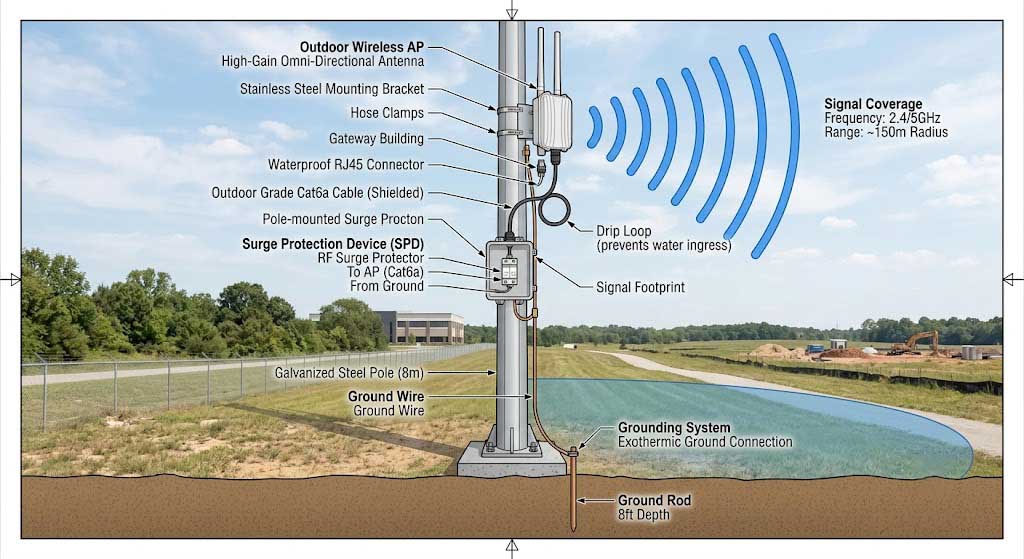
Lightning protection is not optional for outdoor AP installations — it is a safety requirement (NFPA 780, IEEE 802.11 grounding standards) and an insurance requirement for commercial deployments, protecting both the equipment and personnel who may touch it during a storm. A proper lightning protection system has four components: a lightning arrestor on each antenna feedline (mounted at the antenna end of the cable, with a low-resistance path to earth ground), a surge protector on the Ethernet cable at the building entry point (Cat6-rated surge suppressor with gas discharge tube protection, rated for 10kV/5kA), a grounding conductor from the mounting pole/mast to the earth ground system (6 AWG copper minimum, routed in as straight a line as possible — bends increase impedance and reduce protection effectiveness), and the earth ground itself (ground rod driven 2.4m into the earth, resistance to earth < 10Ω measured with a ground resistance tester).
The cost of lightning protection is 10-20% of the total installation cost but provides 90%+ protection against lightning damage, making it the highest-ROI component of any outdoor AP deployment. An AP without lightning protection has a 5-15% annual probability of being damaged by a nearby lightning strike (direct strike within 500m) in most regions, with higher risk in tropical areas (20-30% annual probability in Southeast Asia, Florida, Central Africa). The cost of replacing a single AP + installation is $500-1,500, while the lightning protection cost is $100-300 per AP. Over a 5-year deployment life, the expected value of lightning protection is positive if the annual lightning damage probability exceeds approximately 5-8%. For deployments in high-lightning regions, we also recommend Ethernet surge suppressors with optical isolators (eliminate the conductive path for surge current through the Ethernet cable) and APs with internal surge protection rated to 5kV (IEC 61000-4-5).
Phase 4: Channel Planning and Network Configuration
Channel planning for outdoor WiFi uses the same principles as indoor but with three important differences: the 5GHz band is preferred because 2.4GHz is typically saturated with interference in outdoor urban environments, DFS channels in 5GHz add significant capacity but require radar detection and channel switching that can interrupt service for 30-60 seconds, and adjacent APs must use non-overlapping channels even if physically separated by significant distance because outdoor APs have longer range and more overlap than indoor APs. For a multi-AP outdoor deployment: assign channels so that no two APs with overlapping coverage use the same channel, leave at least one channel spacing between co-located APs (channel 36 and channel 40 overlap at 20MHz width; use channel 36 and channel 44 or wider spacing), and use the 80MHz channel width in 5GHz for maximum throughput but verify that DFS channels are available in the deployment region (some regions prohibit DFS channels for outdoor use).
Outdoor AP configuration should also include: client load balancing (distribute clients across multiple APs based on real-time load, not just signal strength, using 802.11k/v), band steering (prefer 5GHz for dual-band clients, only using 2.4GHz when 5GHz signal is below -72dBm), minimum RSSI thresholds (disconnect clients below -78dBm to prevent “sticky client” problems where a client holds onto a weak AP rather than roaming to a stronger one), and WPA3-Enterprise security with 802.1X authentication using a RADIUS server for mutual authentication and encrypted management frames.
Solar Power Solutions for Remote Outdoor AP
Solar Power System Components — Selection and Sizing
A solar power system for outdoor WiFi consists of 5 components: solar panel (the energy source), charge controller (regulates charging and prevents battery damage), battery (energy storage for night and cloudy periods), enclosure (weatherproof housing for sensitive electronics), and mounting hardware (pole or ground mount for the panel). Each component must be selected and sized for the specific power consumption of the AP and the local solar resource (insolation in peak sun hours per day). The sizing process is: calculate total daily energy consumption (AP power in watts × 24 hours, plus 15-20% for charge controller self-consumption and system losses), divide by the minimum daily peak sun hours at the deployment location (2.5-3.0 PSH for most temperate climates in winter, 4-6 PSH for tropical climates), multiply by 1.3-1.5 for system losses, and select a panel with at least that wattage. For battery sizing: multiply daily consumption by the desired days of autonomy (3-5) and divide by the depth of discharge (DoD) limit of the battery chemistry (50% for lead-acid, 80% for LiFePO4).
| System Size Tier | Applicable AP Scenario | Solar Panel | Battery Capacity | Continuous Power Output | Estimated Cost (Hardware) | Best For |
|---|---|---|---|---|---|---|
| Small (Tier 1) | Single 802.11ac AP (8-12W avg consumption) | 100-150W monocrystalline | 100-150Ah LiFePO4 (1280-1920Wh usable at 80% DoD) | 15-30W continuous (AP + margin) | $600-900 | Remote monitoring, trail cameras, temporary construction sites, agriculture sensors |
| Medium (Tier 2) | Single 802.11ax AP (15-25W) or 2× 802.11ac APs | 200-300W (two 100-150W panels in parallel) | 200-300Ah LiFePO4 (2560-3840Wh usable at 80% DoD) | 30-60W continuous | $1,200-2,000 | Remote base station, campus edge AP, rural Wi-Fi hotspot, small village connectivity |
| Large (Tier 3) | AP + 4G/LTE backhaul (30-45W) or 3-4× 802.11ac APs | 400-600W (4× 100-150W panels in series-parallel) | 400-600Ah LiFePO4 (5120-7680Wh usable at 80% DoD) | 60-90W continuous | $2,500-4,000 | Full-site rural connectivity (AP + backhaul + local switch), community Wi-Fi hub, remote industrial facility |
Installation and Maintenance — Optimizing Solar Harvest and System Longevity
Solar panel mounting is the most important installation factor: panels must be oriented true south (in the northern hemisphere) or true north (southern hemisphere) at a tilt angle equal to the local latitude, with no shading during the peak sun hours of 9:00-15:00 (shading a single cell in a 36-cell panel can reduce total output by 30-50% because of the series connection of cells). In environments with snow, the tilt angle should be latitude + 15° to encourage snow sliding off the panel — a 45-60° tilt is typical for northern climates (latitude 45-50°N). Panels must be mounted with at least 10-15cm of rear ventilation for cooling (panel efficiency drops 0.3-0.5% per °C above 25°C — a panel at 65°C surface temperature has 12-20% lower output than its STC rating at 25°C). In tropical deployments, light-colored panels (bifacial glass-glass panels with white backsheet) operate 5-10°C cooler than standard dark-framed panels, reducing thermal losses by 2-4%.
Battery selection has the greatest impact on system lifetime and total cost of ownership: LiFePO4 (lithium iron phosphate) batteries cost 2-3x upfront but last 5-10 years (3000-5000 cycles at 80% DoD per manufacturer specifications) compared to 2-3 years (500-800 cycles at 50% DoD) for lead-acid AGM batteries. Over a 10-year system life, LiFePO4 has a lower total cost because it requires no battery replacements (lead-acid would need 3-4 replacements at 2-3 year intervals, each costing $150-300). LiFePO4 also has better performance at temperature extremes: 80-90% capacity retention at -20°C vs 50% for lead-acid, and no damage from partial state-of-charge operation (lead-acid suffers sulfation if left at partial charge). The charge controller should be MPPT type (3-5% more efficient than PWM) with temperature compensation for the battery (adjusts charging voltage based on battery temperature to prevent overcharging in hot conditions or undercharging in cold conditions).
Recommended Outdoor AP Products
Zukaka’s outdoor wireless product portfolio is designed around four distinct deployment archetypes rather than a one-size-fits-all approach, allowing system integrators and network engineers to select the optimal platform for their specific range, topology, and power requirements. Each platform shares a common design philosophy: industrial-grade temperature range (-40°C to +70°C), weatherproof PCB conformal coating for humidity resistance, and support for external high-gain antennas. The key differentiators are: wireless standard (802.11ac for high throughput vs 802.11n for extended NLOS range), operating frequency (5GHz for throughput and reduced interference vs 2.4GHz for range and obstacle penetration), power input (48V PoE for standard outdoor deployments vs 24V PoE for solar/battery systems), and Ethernet port configuration (single port for basic installations vs dual ports for daisy-chaining or redundant uplink).
Product Comparison — Technical Specifications by Deployment Archetype
| Product | Standard | Band | Max Range | Throughput | Power Input | Ethernet Ports | Temperature | Optimal Deployment |
|---|---|---|---|---|---|---|---|---|
| 11ac 48V Long-Range Bridge PCBA | 802.11ac Wave 2 (2×2 MU-MIMO) | 5GHz (DFS supported) | 30km PTP (with 30dBi dish antennas and clear Fresnel zone) | 500+ Mbps (up to 867 Mbps PHY rate) | 48V PoE (802.3af/at compatible) | 1× Gigabit Ethernet (PoE in) | -40°C to +65°C (industrial) | Long-distance base station interconnection, campus backbone links, ISP last-mile distribution, connecting remote facility to main network |
| 11ac Dual-Port 48V Bridge PCBA | 802.11ac Wave 2 (2×2 MU-MIMO) | 5GHz (DFS supported) | 30km PTP (same RF performance as single-port version) | 500+ Mbps | 48V PoE (802.3af/at) | 2× Gigabit Ethernet (PoE in + passthrough for daisy-chain or redundant link) | -40°C to +65°C (industrial) | Mission-critical backbone links needing redundancy (dual uplink paths), daisy-chain topology linking multiple APs along a corridor, sites requiring local device connection at the bridge location |
| 5GHz PTP/PTMP Wireless Bridge PCBA | 802.11a/n (2×2 MIMO, RouterOS compatible) | 5GHz only (DFS supported, RouterOS compatible) | 10-15km PTP, 3-5km PTMP (with sector antennas for multipoint) | 170-300 Mbps (PHY rate up to 300 Mbps, typical throughput ~170 Mbps) | 24V Passive PoE (8-30V DC input) | 2× Gigabit Ethernet | -40°C to +70°C (industrial) | Point-to-multipoint coverage (one base station to 5-20 client nodes), hotspot deployment, last-mile distribution to multiple buildings, temporary event networks with flexible topology |
| 11n 24V Wireless Bridge PCBA | 802.11n (2×2 MIMO, 40MHz) | 5GHz (iPoll protocol, 802.11a/n, better anti-interference) | 5-10km PTP (with high-gain directional antennas) | 150-170 Mbps (actual throughput up to 170 Mbps) | 24V Passive PoE (12-24V DC) | 1× Fast Ethernet (100 Mbps) | -40°C to +65°C (industrial) | Cost-sensitive deployments where 2.4GHz NLOS is critical, legacy system upgrades, short-range bridges in obstructed environments (industrial parks, warehouses), solar-powered installations (lower power consumption at 24V) |
Zukaka Solutions for Outdoor AP — Application-Specific Recommendations
| Product | Key Features | Best For |
|---|---|---|
| 11ac 48V Long-Range Bridge PCBA | 30km PTP range, 48V PoE, 500+ Mbps, IP65, 802.11ac Wave 2 MU-MIMO, DFS channel support | Long-range backhaul, base station interconnection, ISP backbone, campus building-to-building links |
| 11ac Dual-Port 48V Bridge PCBA | Dual gigabit ports with PoE passthrough, 30km range, 48V PoE, 500+ Mbps, redundant uplink support | Dual connectivity for mission-critical links, daisy-chain topology for linear deployments (roads, railways, pipelines), redundant backhaul for high-availability sites |
| 5GHz PTP/PTMP Wireless Bridge PCBA | RouterOS compatible, flexible PTP and PTMP topology, 27dBm EIRP, DFS support, compact form factor | Point-to-multipoint coverage for WISP deployments, hotspot zones, campus outdoor WiFi, temporary event networks requiring flexible topology |
Frequently Asked Questions
Q: What IP rating do I need for outdoor AP deployment?
For most outdoor applications, IP65 is the minimum recommended rating — it provides complete dust protection and protection against low-pressure water jets from any direction (typical rain and hose-down exposure). IP67 is required for: locations subject to flooding or standing water (low-lying areas, rooftops with poor drainage, coastal zones where storm surges are possible), areas cleaned with high-pressure hoses (industrial facilities, food processing plants), and any deployment where the AP might be temporarily submerged (condensation drainage channels, areas with snowmelt). IP68 is only needed for extreme industrial environments where APs are mounted in wash-down zones, chemical processing areas, or underwater (flood monitoring, underwater tunnel sensors). A common mistake is selecting IP67 when IP65 would suffice — IP67 enclosures typically have thicker gaskets that can make the AP heavier and more expensive, with no benefit in typical rain-only outdoor environments.
Q: Can I use an indoor AP outdoors with a weatherproof enclosure?
While technically possible, using an indoor AP inside a weatherproof enclosure is not recommended because the enclosure creates a thermal trap that causes the AP to overheat (internal temperature can reach 15-25°C above ambient, easily exceeding the AP’s 40°C maximum rating on a 35°C summer day). Even with ventilation, the enclosure cannot provide the same thermal management as an outdoor AP’s designed heatsink and airflow path. Additionally, the enclosure adds cost ($50-150 for a quality IP66 enclosure with ventilation and cable glands), requires careful cable management (creating potential moisture entry points at the cable glands), and does not address the AP’s lack of conformal coating (moisture that condenses inside the enclosure will still damage the uncoated PCB). Over a 3-year period, indoor APs in outdoor enclosures have a 40-60% failure rate compared to less than 5% for properly rated outdoor APs. The cost of replacing a failed indoor AP every 12-18 months ($150-300 per replacement) plus labor quickly exceeds the cost difference between an indoor AP and an outdoor AP.
Q: What is the maximum range of an outdoor AP and how can I extend it?
With standard integrated omnidirectional antennas (5-8 dBi), outdoor APs typically cover 100-200 meters radius in open line-of-sight conditions — range is limited by the radio’s maximum EIRP (Effective Isotropic Radiated Power), which is regulated by local authorities (FCC maximum 36 dBm EIRP in the US for 5GHz, ETSI maximum 30 dBm EIRP in Europe). To extend range beyond the integrated antenna capability: use high-gain external antennas (a 15dBi panel antenna at 10m height can extend range to 500-800m while staying within regulatory EIRP limits), increase mounting height (doubling height from 5m to 10m extends the radio horizon by approximately 40% due to improved Fresnel zone clearance), or use a point-to-point bridge configuration with two directional antennas aimed at each other (up to 30km with 30dBi dish antennas). However, extending range always involves trade-offs: wider coverage means fewer clients per unit area (if total capacity is fixed), and longer links require higher mounting and precise antenna alignment. For most outdoor WiFi deployments (as opposed to point-to-point backhaul), the practical limit for reliable client connectivity is 200-300m — clients at 500m have very low signal margins and will experience throughput drops during rain, foliage growth, or interference.
Q: How do I power an outdoor AP in a remote location without grid power?
Solar power is the most practical solution for remote outdoor AP locations where the distance to grid power exceeds 50-100m (the break-even point where the cost of trenching power cables exceeds the cost of a solar system). A typical solar system for a single 802.11ac outdoor AP (10-15W average consumption) costs $600-1,500 and includes: a 100-150W monocrystalline solar panel (oriented south/north at latitude angle), an MPPT charge controller, a 100-200Ah LiFePO4 battery (providing 3-7 days of autonomy depending on local insolation), and a weatherproof enclosure. The payback period vs trenching grid power is: at 50m trenching distance ($750-1,500 trenching cost at $15-30/m industry benchmark), the solar system payback is immediate; at 200m distance ($3,000-6,000 trenching cost), solar saves $1,500-4,500. For locations that have seasonal grid power (e.g., seasonal campgrounds, construction sites), a hybrid system with a smaller solar panel and a backup battery charger (for when grid power is available) can reduce the solar system cost by 30-40% while still providing reliable off-grid operation.
Q: What is the difference between WiFi 6 and WiFi 6E for outdoor use?
WiFi 6E extends WiFi 6 (802.11ax) into the 6GHz band (5925-7125 MHz), providing up to 1,200 MHz of additional spectrum in the US (vs 500 MHz in 5GHz) — which translates to up to 7 additional 80MHz channels or 3 additional 160MHz channels that have no interference from legacy WiFi 4/5 devices. For outdoor deployments, WiFi 6E has three practical advantages: dramatically reduced interference (no existing outdoor WiFi 4/5 equipment operates in 6GHz), higher throughput per channel (160MHz channels are practical in 6GHz because the wide spectrum is available), and lower latency (OFDMA in 6GHz is more efficient because there are no legacy devices to contend with). However, WiFi 6E also has two significant limitations for outdoor use: the 6GHz band has higher free-space path loss (approximately 2-3dB more attenuation than 5GHz at the same distance), reducing range by 15-25% compared to 5GHz, and the 6GHz band requires Automated Frequency Coordination (AFC) systems for outdoor deployments in some regions (FCC requires AFC for all outdoor 6GHz Standard Power APs), adding cost and management complexity. For most current outdoor deployments, WiFi 6 in 5GHz remains the practical choice — WiFi 6E will become more relevant for outdoor use after AFC systems are widely deployed and client devices with 6GHz support become mainstream in the outdoor environment (smartphones, laptops, IoT).
Q: Do I need lightning protection for every outdoor AP and at what cost?
Yes, lightning protection is essential for every outdoor AP installation, regardless of deployment location — even in areas with low lightning frequency (less than 5 thunderstorm days per year), nearby lightning strikes within 500m can induce damaging surges on antenna cables and Ethernet lines. The cost of lightning protection is $100-300 per AP (lightning arrestor on antenna cable $30-60, Ethernet surge protector $40-80, grounding conductor and hardware $30-100, ground rod $20-60) plus installation labor (1-2 hours at $75-150/hr if a ground rod must be driven). This represents 10-20% of the total outdoor AP installation cost but provides 90%+ protection against lightning damage. Without protection, a single lightning strike can destroy not only the AP but also the switch, router, and other network equipment connected to the same cable — a single surge event can cause $2,000-10,000+ in equipment damage. For installations on existing structures (building rooftops, existing masts), the grounding system is often already in place, reducing the lightning protection cost to $50-100 per AP for the arrestors and surge protectors only.
Q: How many concurrent users can an outdoor AP support and what limits this?
Entry-level outdoor APs (802.11ac, 2×2) support 30-50 concurrent clients in typical outdoor deployments, while enterprise-grade outdoor APs (802.11ax, 4×4 with OFDMA and MU-MIMO) can support 100-200+ concurrent clients — but these numbers depend heavily on the application mix and signal quality of the clients. The practical limit is determined by: channel utilization (each active client consumes airtime for data transmission + protocol overhead — the more clients, the less airtime per client), signal quality (clients at -70dBm use 2-3x more airtime to transmit the same amount of data as clients at -55dBm because they need lower MCS rates), and application requirements (web browsing uses 0.5-2 Mbps per session, video streaming uses 5-25 Mbps per stream, and VoIP uses 0.1-0.3 Mbps per call — a 150 Mbps PHY rate AP can support 75-150 Mbps of actual throughput after protocol overhead, which translates to 30-75 simultaneous video streams vs 300-750 web browsing sessions vs 1500-3000 VoIP calls). For outdoor deployments where clients are mobile and signal quality varies, we recommend designing for 20-30 clients per AP for mixed application use, or up to 50 clients per AP if the application mix is dominated by low-bandwidth IoT traffic.
Q: What security features should I configure on an outdoor AP beyond basic WPA2?
Beyond WPA3-Enterprise with 802.1X authentication, outdoor APs exposed to public access should be configured with: a separate guest VLAN with internet-only access (no access to the corporate LAN), bandwidth limiting per client (5-10 Mbps per client to prevent one user from consuming all available bandwidth), client isolation (preventing wireless clients from communicating directly with each other), a captive portal or pre-shared key rotation for guest access management, and regular firmware updates (at least quarterly for security patches). Outdoor APs in public spaces are exposed to additional physical security risks: an attacker could perform a “de-authentication attack” by sending de-auth frames to disconnect clients (mitigated by 802.11w management frame protection, which is mandatory in WiFi 6), or perform a “rogue AP attack” by placing a fake AP with the same SSID to capture credentials (mitigated by 802.1X with mutual authentication where clients verify the AP’s certificate). For outdoor APs in sensitive environments (government, financial, critical infrastructure), we also recommend: disabling SSID broadcast for the management network, using IPsec or MACsec for backhaul encryption between the AP and the controller, and configuring the AP to automatically disable itself if physical tampering is detected (tamper switch or enclosure-open alarm).
By: Alex Chen, Senior RF Engineer — Zukaka Engineering Team |
Last Updated: June 14, 2026 |
CWNA Certified · 12+ years in wireless infrastructure design · Former Cisco partner engineer
⭐⭐⭐⭐⭐ OEM/ODM Partner
“Zukaka PCBA modules have been integral to our industrial wireless product line. The engineering team’s responsiveness and the modules’ reliability in harsh environments have made them our preferred supplier for three consecutive years.”
— VP of Engineering, Industrial Wireless Equipment Manufacturer
⭐⭐⭐⭐⭐ System Integrator
“We’ve integrated Zukaka wireless bridge PCBA into our smart city and industrial IoT deployments. The industrial temperature range and long-range capabilities have consistently exceeded our specifications.”
— Technical Director, Systems Integration Company
✔ Certifications: FCC, CE, RoHS compliant |
✔ Industrial temperature range -40 to +70 °C |
✔ IP65-rated for outdoor deployment
Contact our engineering team for customized PCBA solutions and technical support.