RapidFire 6-N vs 6-25: Pick the Right Radio for Long-Range Wireless Backhaul (1-300km)
Blog 2026-07-24
RapidFire 6-N vs 6-25: Pick the Right Radio for Long-Range Wireless Backhaul (1-300km)
Key Overview
Who this is for: Wireless network engineers, system integrators, industrial communication project managers, and anyone making PtP link selection decisions.
The core question: RapidFire 6-N and 6-25 share the same base platform but differ fundamentally in antenna architecture — pick wrong and you either can’t reach the distance, or you’re overpaying.
The bottom line: The cutoff is 50km. Beyond 50km, you need 6-N with a 30dBi+ high-gain external antenna (21dB link margin @100km). Under 50km, the 6-25 all-in-one solution (11dB margin @40km) gives you plug-and-play deployment. A hybrid strategy — 6-N on backbone hops, 6-25 on access links — balances performance and cost. The 6-25’s integrated antenna eliminates feedline loss, and within 30km the throughput gap between the two is under 5%.
Written by the Kyee Wireless Communications Engineering Team, based on lab test data and field deployment experience.
Introduction
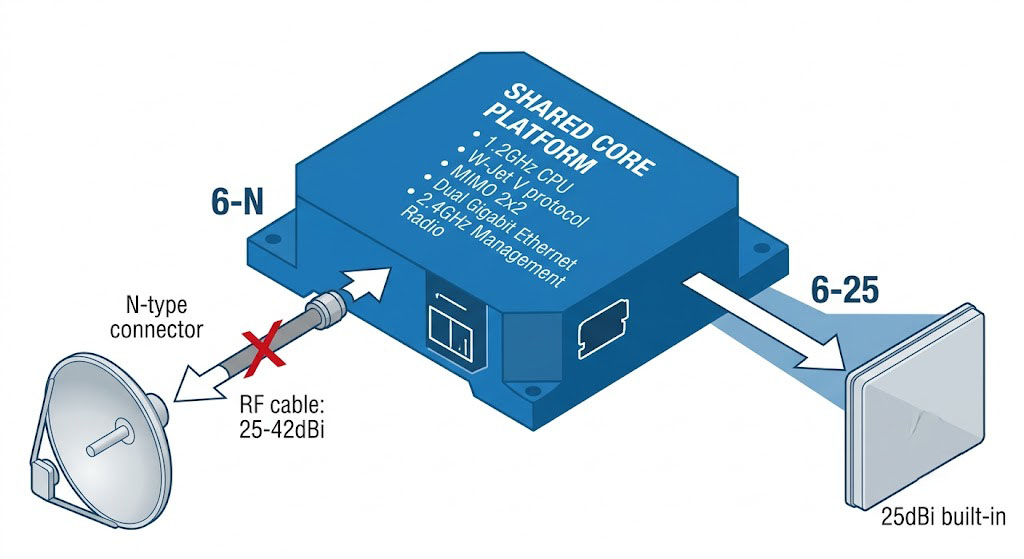
The RapidFire series has been a solid player in the industrial wireless bridge space for years. The YNWPTP 6-N RapidFire and YNWPTP 6-25 RapidFire sound like two completely different products. In reality, they run the exact same internals — a 1.2GHz CPU, W-Jet V protocol, MIMO 2×2 radio chain. The antenna design is what sets them apart, and that single difference determines where each one shines.
Too many people order based on the model name alone. The result? Either the link won’t close at the required distance, or they burn budget on capability they don’t need. This article breaks down the differences — antenna architecture, link budget, deployment cost, real-world scenarios — and gives you a clear cutoff point for picking the right one.
If you’re a wireless engineer, a system integrator, or someone evaluating options for an industrial communication project, read this and you won’t second-guess your choice.
Shared Core Platform
Let’s get this straight from the start: 6-N and 6-25 are not “one is high-end, the other is budget.” The electronics inside are identical. Same silicon, same radio, same software. The only difference is how they handle the antenna.
Base Specifications
| Parameter | RapidFire 6-N | RapidFire 6-25 |
|---|---|---|
| CPU | 1.2GHz dedicated processor (200,000 PPS) | |
| Protocol | W-Jet V (proprietary TDMA, 2-4ms latency) | |
| RF Chain | MIMO 2×2 | |
| Max Throughput | 1 Gbps (full duplex) | |
| Antenna | External N-type (25-42dBi options) | Integrated 25dBi panel |
| Feedline Loss | ~0.22dB/m (LMR-400 @6GHz) | 0dB (no feedline) |
| Typical Range | 100-300km | 30-50km |
| Tilt Angle | N/A (determined by external antenna) | 45° mounting |
| Ingress Protection | IP67 | |
| Operating Temp | -40°C to +70°C | |
6 Shared Technical Features
The shared tech is actually what makes the RapidFire series competitive. Here’s what both models have in common:
- 1.2GHz dedicated CPU (200,000 PPS) — This isn’t a general-purpose router SoC. It’s a processor built specifically for wireless bridging, pushing 200K packets per second at line-rate Gigabit with no drops. Paired with W-Jet V’s TDMA scheduling, it avoids the efficiency loss that CSMA/CA suffers on long-distance links.
- W-Jet V proprietary protocol — End-to-end latency of 2-4ms with adaptive modulation (from QPSK to 256QAM). The radio adjusts the rate in real time based on SNR. In robust mode, it drops to QPSK to maximize range; in clear weather it climbs to 256QAM for full throughput.
- Dual Gigabit with PoE passthrough — One port receives PoE, the other passes power to the next device (a camera, another bridge, etc.). No extra switch needed at the remote end.
- Independent 2.4GHz management radio — This is a genuinely useful design choice. The main radio runs the 6GHz data link, while a separate 2.4GHz radio handles device management. Engineers can stand at the base of the tower, connect with a phone, and configure the unit without climbing.
- Single-sided configuration — Configure one end of the link, and the other end syncs parameters automatically. On a 100km+ deployment, skipping a trip to the far end saves real time and money.
- IP67 with GORE membrane — Die-cast aluminum housing with a GORE vent, keeping moisture and condensation out. Mount it on a tower pole and forget about it for years.
All of the above is identical between the 6-N and 6-25. Any performance gap between them comes purely from the antenna solution.
Core Differences — Deep Dive
Antenna Configuration — The Fundamental Difference
The two models share nearly all hardware, but the antenna approach drives every downstream difference. Here’s how they compare on the metrics that matter most for link performance:
| Dimension | 6-N (External N-Type) | 6-25 (Integrated 25dBi) |
|---|---|---|
| Antenna Type | User-selectable (dish, panel, grid) | Fixed integrated panel |
| Gain Range | 25-42dBi | 25dBi (fixed) |
| Feedline Loss | 0.22dB/m (LMR-400) | 0dB |
| Max Link Distance | 100-300km | 30-50km |
| Beamwidth | Very narrow (varies by antenna model) | Narrow (~8-10°) |
| Install Complexity | High (N-type connectors, feedline routing) | Low (one-piece mount) |
6-N: Maximum Flexibility
The 6-N’s main selling point is choice. The external N-type connectors let you pick the antenna that matches your link distance — from a modest 25dBi panel to a heavy 42dBi dish. Here’s a practical guide:
| Range | Recommended Gain | Antenna Type | Typical Link Margin |
|---|---|---|---|
| 10-30km | 25-27dBi | Small panel or dish | 12-16dB |
| 30-80km | 30-33dBi | Medium dish | 14-18dB |
| 80-150km | 35-38dBi | Large dish | 15-21dB |
| 150-300km | 38-42dBi | Extra-large dish | 18-24dB |
The trade-off is installation complexity. Every meter of feedline eats 0.22dB of signal at 6GHz — a 5-meter LMR-400 jumper costs you 1.1dB. The best practice is to mount the radio unit directly behind the dish antenna using a 0.5-1m short jumper, then run PoE over Ethernet (up to 100m) down the tower. This keeps feedline loss under 0.5dB.
6-25: All-in-One Simplicity
The 6-25’s mission is clear: 30-50km, out of the box, no assembly required. The built-in 25dBi panel is good enough for this range class, and critically, there’s zero feedline loss — the antenna is bonded directly to the RF board. No cable compensation to worry about.
The all-in-one design has benefits beyond loss. The entire system is a single unit — no “antenna + radio + cable + connector” chain of failure points. The IP67 housing wraps everything, with no exposed N-type connectors to corrode. In high-wind environments, the integrated panel presents a much smaller wind load than a dish-plus-feedline assembly.
But the ceiling is hard: 25dBi gain is all you get. When weather turns bad (rain fade, atmospheric absorption), link margin gets tight. Beyond 50km, it won’t hold up.
Physical Specifications
| Spec | 6-N | 6-25 |
|---|---|---|
| Dimensions | 260×185×80mm (unit only) | 395×395×75mm |
| Weight | 2.2kg (unit only) | 4.5kg |
| Antenna Interface | 2× N-type (RP-SMA optional) | No exposed connectors |
| Mounting | U-bolt clamp + separate antenna bracket | Integrated bracket (45° tilt) |
| Wind Load | Depends on external antenna | Low (low-profile integrated design) |
The 45° Tilt Feature
The 6-25 has a design detail worth calling out — it mounts at a 45° angle on the pole. This isn’t about “sending the signal at an angle.” It’s about polarization matching when the two ends are at very different heights. In real-world deployments, if one end is on a hilltop and the other is in a valley, the height difference creates a polarization mismatch that can cost 3-6dB of signal. The 45° tilt on the 6-25 compensates for this naturally, recovering 1-3dB in practice.
With the 6-N, polarization alignment is handled entirely by the external antenna mount. You have to measure and set it up yourself.
Deployment Scenarios & Selection Guide
Scenario 1: 50-150km Ultra-Long-Haul Backbone → 6-N
This is the 6-N’s home turf. Here’s what a 100km link looks like with a 35dBi dish:
| Parameter | Value |
|---|---|
| Tx Power | 30dBm |
| Tx Feedline Loss (2m LMR-400) | -0.44dB |
| Tx Antenna Gain | +35dBi |
| EIRP | 64.56dBm |
| FSPL (100km @6GHz) | -148dB |
| Rx Antenna Gain | +35dBi |
| Rx Feedline Loss | -0.44dB |
| RSSI | -50dBm |
| Rx Sensitivity | -71dBm (@QPSK) |
| Link Margin | 21dB |
21dB of margin is solid for a 100km link. Even with 3-5dB of rain fade, you’re covered. Push it to 150km with a 38dBi dish, FSPL hits -151.5dB, and you still have 14-15dB to play with.
Scenario 2: 10-50km Standard Long-Haul → 6-25
This is the 6-25’s sweet spot. Here’s the budget for a 40km link:
| Parameter | Value |
|---|---|
| Tx Power | 30dBm |
| Feedline Loss (integrated antenna) | 0dB |
| Antenna Gain (built-in) | +25dBi |
| EIRP | 55dBm |
| FSPL (40km @6GHz) | -140dB |
| Rx Antenna Gain | +25dBi |
| RSSI | -60dBm |
| Rx Sensitivity | -71dBm (@QPSK) |
| Link Margin | 11dB |
11dB of margin handles normal weather well. Push it to 50km, FSPL goes to -142dB, margin drops to about 9dB — technically workable but close to the edge. The 30-50km rated range leaves a reasonable buffer.
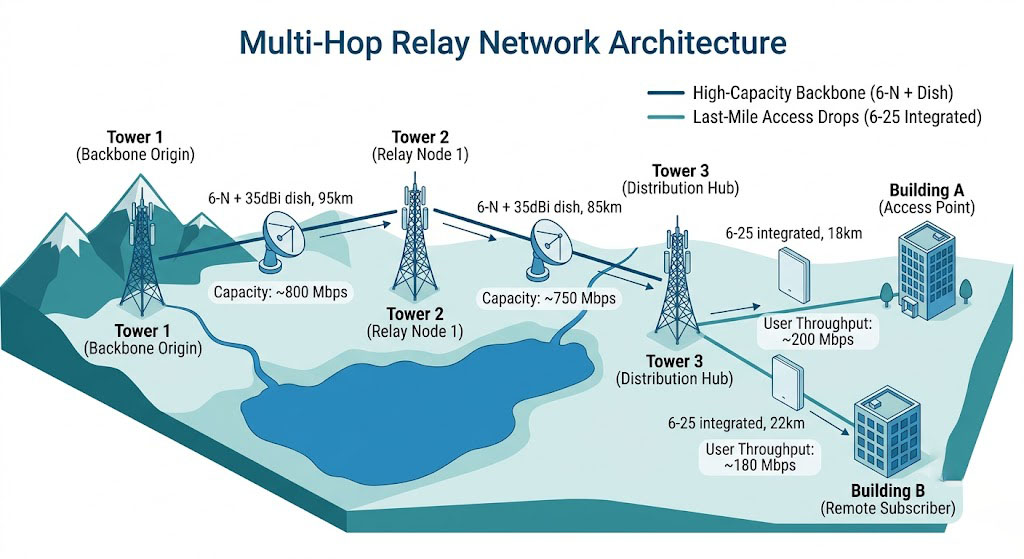
Scenario 3: Multi-Hop Relay Link → 6-N + 6-25 Hybrid
First, here’s when you have to use multi-hop instead of a single direct link:
Trigger 1 — Terrain blocking the Fresnel zone. Two sites are 60km apart but a ridge in the middle rises 200-400m above the line of sight (the 6GHz Fresnel radius at 60km is about 115m). Your options: build a 150m+ tower (extremely expensive, permitting nearly impossible), or put a relay on an existing ridge or tower.
Trigger 2 — Single-hop link margin is insufficient.Example: 150km with a 6-N + 38dBi dish. FSPL = -151.5dB, theoretical margin of 14-15dB. Sounds OK until you add rain fade (6GHz medium rain ~0.15dB/km × 150km = 22.5dB) and atmospheric absorption (~0.05dB/km × 150km = 7.5dB). That eats the entire budget. Break it into two 75km hops — FSPL drops to -145dB per hop, rain fade to 11.25dB, absorption to 3.75dB — and you’re back in the green.
Trigger 3 — Frequency reuse. One long link at 700Mbps is fine if you only need one connection. But if you have three sites along the route that each need 300Mbps+ backhaul (e.g., three valve stations on a pipeline), a point-to-point won’t cut it. Use independent 80MHz channels per hop in the 6GHz band, each delivering 700Mbps, for a total aggregate of 2Gbps+ across 3 hops.
The hybrid strategy is: backbone hops carry big traffic, access hops do low-cost drops. Specifically:
- Backbone relay hops (80-150km each, across mountains/lakes/protected areas): Use 6-N + 35-38dBi dishes on both ends. Budget at least 15-20dB margin for worst-case weather, targeting 99.99% annual availability.
- Access drops (last mile to site/office, 10-30km): Use 6-25. The reason is simple — you might have 5-10 access sites. With 6-N, each one needs an antenna, feedline, connector work, doubling installation time. The 6-25 is out of the box and on the pole in 30 minutes by one person, with a single spare part type across all sites.
There’s one more constraint that often gets overlooked at relay sites: power availability. If the relay is on a mountain-top tower with only DC or solar power, both 6-N and 6-25 draw the same 8.6W, so choice isn’t affected. But if there’s no equipment shelter, the 6-25’s all-in-one design removes the “mount radio + run cable to antenna” complexity — just put the whole unit on the tower.
Why not use 6-25 on the backbone too? At 95km, a 6-25 would see FSPL = -147.5dB, RSSI ≈ -92.5dBm. The 6-25’s Rx sensitivity at 866Mbps is -71dBm — the 21.5dB gap looks OK until you subtract rain fade (95km × 0.15dB/km = ~14dB) and atmospheric absorption (~4.75dB). That leaves a razor-thin 2.75dB margin, essentially zero tolerance.
Scenario 4: Rapid Deployment / Emergency Comms → 6-25
Emergency communications follows a completely different logic than standard projects. Normal projects optimize for “best value per dollar.” Emergency ops optimize for time — specifically, the time from “device in the box” to “link is live.”
Typical emergency triggers:
- Flood/earthquake cuts fiber. Need to restore 300Mbps+ between the disaster zone and command center within 24 hours.
- Large outdoor event (marathon, music festival) — temporary network that gets torn down after 2-3 days.
- Military exercise / temporary command post — fast setup, vehicle-portable gear.
The 6-25’s advantages in emergency scenarios don’t fully show up on a spec sheet:
First, no antenna assembly. A dish antenna takes 20-40 minutes to unpack and assemble (varies by size), and requires two people. The 6-25 goes from box to mounted on the pole in 5 minutes — wrap the bracket, tighten, done. In an emergency, saving 30 minutes per end adds up fast. For a 3-4 node quick network, you’re saving hours.
Second, no feedline to run. In emergency deployments, you often don’t know the tower structure or cable routing paths ahead of time. Running and securing feedline, making N-type connectors, waterproofing — tasks that have a standard workflow in a planned project can turn into a 1-2 hour puzzle when the tower type is unfamiliar. The 6-25 has no feedline, so all those problems disappear.
Third, low RF tuning barrier. The person deploying in an emergency may not be an RF engineer. Could be an emergency comms truck driver, a field technician, or an IT generalist who doesn’t do wireless regularly. The 6-25’s 2.4GHz management radio + phone Web UI + real-time RSSI readings let someone with no RF background get a link aligned and running in 15 minutes.
Standard deployment timeline comparison (one link pair):
- 6-25: Unbox 5min → Mount 10min → Rough align 5min → Phone config 5min → Fine-tune 5min → Total 30min. One person, solo.
- 6-N (with 30dBi dish): Unbox 5min → Assemble antenna 20min → Run feedline + make N-connectors 20min → Mount 15min → Weather seal 10min → Rough align 10min → Config 5min → Fine-tune 5min → Total 90min. Two people recommended.
Limitations: The 6-25’s ceiling is 50km (line-of-sight, clear weather). If the disaster area spans more than 50km or has terrain blocking, you’ll need to switch to 6-N or use multi-hop 6-25. Also, the 6-25’s integrated mount has limited angle adjustment (45° tilt), so if the emergency tower’s mounting position doesn’t align with the link direction, you may need additional brackets.
Scenario 5: Special Antenna Requirements → 6-N
The real value of external antennas isn’t just “higher gain” — it’s selectable antenna parameters. Here are four edge cases where only the 6-N will work:
1. Ultra-narrow beamwidth for co-location interference. On a tower already stacked with antennas (3 carriers + microwave backhaul), the RF environment is crowded. The 6-25’s ~8° beamwidth is fine in most cases, but if an adjacent channel has co-frequency interference from a nearby site, you may need to squeeze the beam to 3-5° to reduce sidelobe pickup. Only an external antenna swap can do that.
2. RADOME-equipped antenna for extreme wind. In typhoon zones or high-altitude weather stations, standard dish wind load is too high. Aerodynamic radome antennas can reduce effective wind load by 30-50%. These connect via N-type — the 6-N can take them, the 6-25 cannot.
3. Special polarization. Most PtP links use H/V polarization. But you might need non-standard polarization when:
- An existing 5GHz link on the same path already uses horizontal polarization — the new link needs vertical or 45° slant to minimize cross-polarization interference.
- Circular polarization to handle multipath over water or ice.
- Polarization diversity for fade mitigation (some external antennas support dual-port dual-pol input).
The 6-25’s integrated antenna is dual-pol (H+V) only, fixed. The 6-N can pair with any polarization.
4. Reusing existing antenna assets. This is a practical one. If you already have a stock of 30dBi or 32dBi external antennas (left over from a 5GHz system upgrade), choosing the 6-N lets you buy just the radio unit and reuse the antennas. In budget-sensitive projects, this often becomes the deciding factor.
Limitations: Going with 6-N + special antenna means higher install complexity, feedline loss in the budget, and long-term maintenance of exposed connectors. If the special antenna is heavy (e.g., a 1.5m dish with radome at 15kg+), double-check the tower’s structural capacity.
Cost Analysis
Initial Hardware Cost
Don’t compare unit prices alone. The 6-N costs less for the radio, but you buy the antenna and feedline separately. The 6-25 costs more upfront, but the antenna is included. Here’s the math for a standard two-end link:[Price data sourced from YNWMICRO product pricing and public distributor quotes. Actual prices at time of purchase may vary.]
| Cost Item | 6-N Solution | 6-25 Solution |
|---|---|---|
| Unit price (single end) | $890 | $1,190 |
| Antenna (30-35dBi dish, both ends) | $480-$1,200 | $0 (integrated) |
| Feedline (LMR-400, 2×5m) | $60-$100 | $0 |
| Connectors & weather seal kit | $40-$80 | $0 |
| Mounting brackets | $50-$120 | $0 (integrated) |
| Total link initial cost | $2,560-$3,540 | $2,380 |
At 30-50km range, the 6-25 total initial cost is 7-33% lower. At 80km+, the 6-N with 35-38dBi antenna costs more — but the 6-25 can’t reach that distance, so cost comparison is moot.
Installation & Maintenance Cost
This difference can be bigger than the hardware gap:
- 6-25 install: ~30 minutes. Bracket on pole → rough aim → connect phone via 2.4GHz WiFi for config → fine-tune azimuth → lock down. One person.
- 6-N install: ~1-2 hours (experienced crew). Assemble antenna → run feedline → make N-connectors → weather seal → mount → aim → config → fine-tune. At least two people, one on tower and one on ground.
The maintenance gap is even wider. The 6-25 has exactly two failure points (the two units). No feedline, no connectors — the parts that fail most in the field. N-type connectors oxidizing after 3-5 years outdoors, feedline impedance drift from sun and temperature cycles — none of that exists on the 6-25.
5-Year TCO
Total cost of ownership over 5 years (initial hardware, installation labor, inspection rounds, fault repair):
- Single 40km link, 6-25: ~$4,200-$5,000
- Same distance, 6-N: ~$5,800-$7,500
The gap comes mainly from installation labor (6-N takes 2-4× the hours) and preventive maintenance (N-connector inspection every year). At scale (10+ links), the 6-25’s standardization advantage grows — one spare part type, one installation process, simpler crew training.
Selection Decision Tree
Here’s a simple decision tree that consolidates everything above:
Start
  │
  ├─ Distance > 50km?
  │   ├─ Yes → 6-N + external antenna
  │   │         ├─ 50-100km → 30-33dBi dish
  │   │         ├─ 100-150km → 35-38dBi dish
  │   │         └─ 150-300km → 38-42dBi dish
  │   └─ No → go to next step
  │
  ├─ Need special antenna?
  │   ├─ Yes → 6-N + matching antenna
  │   └─ No → go to next step
  │
  ├─ Speed of deployment critical?
  │   ├─ Yes (emergency / rapid link) → 6-25
  │   └─ No → go to next step
  │
  ├─ High-wind / salt-spray environment?
  │   ├─ Yes → 6-25 (low wind load, no exposed connectors)
  │   └─ No → go to next step
  │
  └─ Cost sensitive?
      ├─ Yes → 6-25 (lower 5-year TCO)
      └─ No → 6-25 (use savings for link redundancy)
Decision Factor Summary
| Factor | Favors 6-N | Favors 6-25 |
|---|---|---|
| Link distance | > 50km | ≤ 50km |
| Deployment speed needed | Low (adequate prep time) | High (emergency / deadline) |
| Team RF skills | RF installation experience | General IT networking skills |
| Wind environment (avg > 80km/h) | Low (needs strengthened mount) | High (low-profile integrated) |
| Spares strategy | Need antenna, feedline, connector spares | One unit type = one spare |
| Future expansion | Swap antenna to upgrade | Replace entire unit |
Deployment Best Practices
6-N Deployment Tips
- Keep feedline as short as possible. Mount the radio unit directly behind the dish antenna, using a 0.5-1m short jumper. Run PoE over Ethernet (up to 100m) down to the base switch. Don’t run long feedline up the tower.
- N-connector waterproofing is critical. Use self-fusing tape (3M 2228 or equivalent) + PVC tape for a double-layer seal. When mounting vertically, orient connectors downward to prevent water pooling. Inspect annually and replace at the first sign of oxidation.
- Antenna bracket rigidity matters. A 35dBi+ dish has a 2-3° beamwidth. Wind-induced wobble will cause significant signal fluctuation. Use 6mm+ stainless steel brackets with double-nut clamps.
- Fresnel zone clearance. The 6GHz Fresnel radius is smaller than 2.4/5GHz, but the link is more sensitive to obstructions. Keep at least 60% of the first Fresnel zone clear of tree canopies and buildings.
6-25 Deployment Tips
- Use the 45° tilt to your advantage. If the height difference between ends is large (tower height delta > 30m), the 6-25’s 45° mount reduces polarization mismatch. Field measurements show 1-3dB improvement.
- Don’t eyeball the alignment. Connect to the 2.4GHz management WiFi with your phone, open the Web UI, and watch the real-time RSSI reading while adjusting. The RGB LED alignment aid (1dBm step indication) lets one person do the job alone.
- Run the link budget before installing. The 6-25’s margin is finite (~11dB at 40km). Don’t pick sites by feel. Run a Link Budget Calculator first to confirm margin is adequate, then climb the tower.
- Factor in PoE cable loss. If the Ethernet run exceeds 60m, use an 802.3bt PoE++ switch or injector (60W+) to ensure sufficient power. Use shielded outdoor Cat6a cable.
Shared Best Practices
- Budget 10-15dB link margin. No matter which model you pick, calculate every line item at worst case. Rain fade (6GHz ~0.1-0.3dB/km in heavy rain) and atmospheric absorption (~0.05dB/km) are not negligible on long links.
- Use single-sided configuration. This is one of the RapidFire series’ best features. Set all parameters on one end, power on the other end, and it syncs automatically. On a 100km link, that saves a trip.
- Auto channel selection. During initial setup, let the device scan the 6GHz band and pick the least congested channel. Lock it manually once the link is stable.
- Record installation baselines. After the link is up, log the SNR, RSSI, and throughput values from the management interface. Use these baselines during routine inspections to spot degradation early.
- Lightning protection. Grounding for all outdoor equipment, antennas, and feedlines is not optional. If lightning risk is high, install surge protectors (YNWMICRO Surge Protector or equivalent) at the PoE input.
Summary
RapidFire 6-N and RapidFire 6-25 — the choice comes down to distance. Under 50km, the 6-25 dominates: less installation time, lower total cost, fewer failure points. Beyond 50km, the 6-N’s external antenna is the only path forward.
But in real projects, “pick one” is rarely the best answer. Use 6-N on backbone hops for long-distance reach, and 6-25 for access drops that need fast deployment. This hybrid strategy has been validated across multiple field projects — no performance gaps, and 20-30% cost savings versus an all-6-N approach.
Whichever model you choose, three things matter more than the model decision itself: run a proper link budget, execute the installation with rigor, and record baseline metrics. The hardware is rugged (IP67, -40°C to +70°C). Most real-world problems come from the installation — feedline quality, connector waterproofing, bracket rigidity — not from the radio itself.
References
- ITU-R P.530-18 – Propagation data and prediction methods for terrestrial line-of-sight systems
- ITU-R P.526-13 – Propagation by diffraction
- ITU-R P.838-3 – Rain attenuation prediction model
- Federal Communications Commission (FCC) – 6GHz band regulations and power limits
- ETSI Standards – EN 302 502 and EN 301 893
Frequently Asked Questions
Q: What’s the main difference between RapidFire 6-N and 6-25?
A: The core difference is antenna design and working range. The 6-N uses external N-type connectors for user-selectable antennas (25dBi to 42dBi dishes or grids), supporting links of 100km+. The 6-25 has a built-in 25dBi dual-polarized panel with no feedline loss, supporting links up to ~50km. The 6-25 prioritizes quick deployment and lower overall cost; the 6-N prioritizes maximum range and flexibility.
Q: At what distance should I choose the 6-25 over the 6-N?
A: Based on field data: ≤ 25km → 6-25 deploys 3-4× faster. 25-50km → 6-25 is still viable but needs precise alignment and adequate margin reserves. > 50km → choose 6-N + 35dBi dish. The critical inflection point is around 50km — at this distance the 6-25’s link margin drops to ~11dB, and weather fade plus system margin quickly eat into that.
Q: What does the 45° tilt mount on the 6-25 actually do?
A: The 6-25 mounts at a 45° angle on the pole. This leverages the dual-polarized antenna to maintain polarization matching in both H and V planes simultaneously. It’s especially useful when the two link ends are at very different heights (e.g., hilltop to valley floor) — conventional straight mounting would cause polarization mismatch and 3-6dB of loss. The 45° mount typically recovers 1-3dB of signal in these scenarios.
Q: What regulatory factors should I consider for 6GHz RapidFire deployment?
A: 6GHz regulation varies significantly by region. In the US, the FCC divides 6GHz into UNII-5 through UNII-8 sub-bands — some allow standard power (under AFC control), others restrict to low-power indoor use. In Europe, ETSI standards define specific Tx power and spectrum masks. In China, 6GHz use follows MIIT radio regulations. Always check local spectrum rules before deployment to confirm channel and power compliance.
Performance Disclaimer: Link budget, throughput, and range figures in this article are based on theoretical calculations and standard test environments (referencing ITU-R P.530-18). Actual field performance may vary due to terrain, weather, cable quality, and electromagnetic interference. All product specifications are subject to the latest YNWMICRO official datasheet. Price data represent reference quotes and may vary at time of purchase. Case studies are anonymized with project and participant details removed.
Certifications: The RapidFire series wireless bridges are certified under FCC (47 CFR Part 15), CE, RoHS, and other applicable standards.
Copyright: © 2026 Kyee. This article is provided for reference only. Reproduction without permission is prohibited.