RapidFire Long-Distance PTP Link Deployment Guide: From 1km to 300km — Complete Field Manual
Key Overview
Who this is for: Network engineers, ISP techs, IT ops in oil & gas, mining, and island deployments — anyone who needs to bridge 10–300km when fiber is too expensive or slow.
Core Issue: When fiber cabling costs too much or takes too long, how do you plan, deploy, and maintain a rock-solid ultra-long-range PTP wireless link using RapidFire hardware?
Key Conclusions: A 50km RapidFire 6-N link with a high-gain antenna costs 20–30% of an equivalent fiber run, deploys in 1–2 weeks, and delivers 99.9%+ availability. For 100km+ links, the three make-or-break factors are link budget accuracy, Fresnel zone clearance, and antenna alignment precision.
Introduction
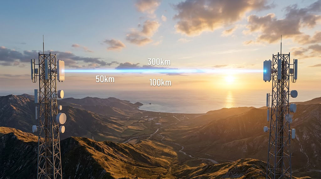
Connecting two networks tens or hundreds of kilometers apart usually means staring down a brutal price tag — fiber trenching, permits, months of civil work. YNWPTP RapidFire, especially the 6-N model paired with a high-gain external antenna, gives you a proven wireless alternative. Take a 50km link: total deployment cost lands at 20–30% of fiber, deployment drops from months to 1–2 weeks, and you still get 99.9%+ link availability.
But throwing a 100km+ wireless link together isn’t just “mount the radio and aim the dish.” Every step — link budget, site selection, antenna choice, Fresnel zone analysis, long-term reliability — determines whether the link hits its design target. This guide walks through the full lifecycle of an ultra-long-range PTP deployment using RapidFire. For context on where RapidFire fits in the broader industrial wireless bridge lineup, check out the Complete Guide to Industrial Wireless Bridges.
Link Planning Fundamentals
2.1 Link Budget Calculation — The Math That Decides if Your Link Works
The link budget is the core of any wireless link plan. It sums up every gain and loss along the signal path from transmitter to receiver, giving you the received signal strength (RSSI). Compare RSSI against receiver sensitivity, and you get the fade margin.
Link Budget Formula:
RSSI (dBm) = TX Power (dBm) - Cable Loss_TX (dB) + Antenna Gain_TX (dBi) - FSL (dB) + Antenna Gain_RX (dBi) - Cable Loss_RX (dB)
This calculation follows the [ITU-R P.525] free-space propagation model and the [ITU-R P.530-18] terrestrial LOS design method. Rain attenuation estimates reference [ITU-R P.838-3]. For non-ideal LOS, [ITU-R P.526-13] diffraction model helps assess additional loss.
Free-Space Loss Formula:
FSL (dB) = 32.45 + 20 × log(freq MHz) + 20 × log(dist km)
For a 100km link at 6,000MHz:
FSL = 32.45 + 20 × log(6000) + 20 × log(100)
    = 32.45 + 20 × 3.778 + 20 × 2
    = 32.45 + 75.56 + 40
    = 148.01 dB
Complete Link Budget (100km, 6-N + 1.8m dish, 35dBi):
| Link Budget Item | Value | Notes |
|---|---|---|
| TX Power | +30 dBm | RapidFire max TX power |
| TX Cable Loss | -1.0 dB | 3m LMR-400 @ 6GHz |
| TX Connector Loss | -0.5 dB | Two N-type connectors |
| TX Antenna Gain | +35 dBi | 1.8m dual-pol dish |
| EIRP | +63.5 dBm | 30-1-0.5+35 = 63.5 |
| Free-Space Loss (100km) | -148.0 dB | @6000MHz |
| Atmospheric Absorption | -1.0 dB | Typical @ 6GHz |
| RX Antenna Gain | +35 dBi | Same spec |
| RX Connector Loss | -0.5 dB | Connector loss |
| RX Cable Loss | -1.0 dB | 3m LMR-400 |
| RSSI | -52 dBm | Total: 30-1-0.5+35-148-1+35-0.5-1 |
| RX Sensitivity @ 866Mbps | -71 dBm | 256-QAM 5/6 |
| Fade Margin | +19 dB | -52 – (-71) = 19 |
A 19dB fade margin means the link keeps running at full rate even during heavy rain (6GHz rain fade runs roughly 1–2dB/km in a downpour).
2.2 Fresnel Zone Analysis — The Real Constraint on LOS Links
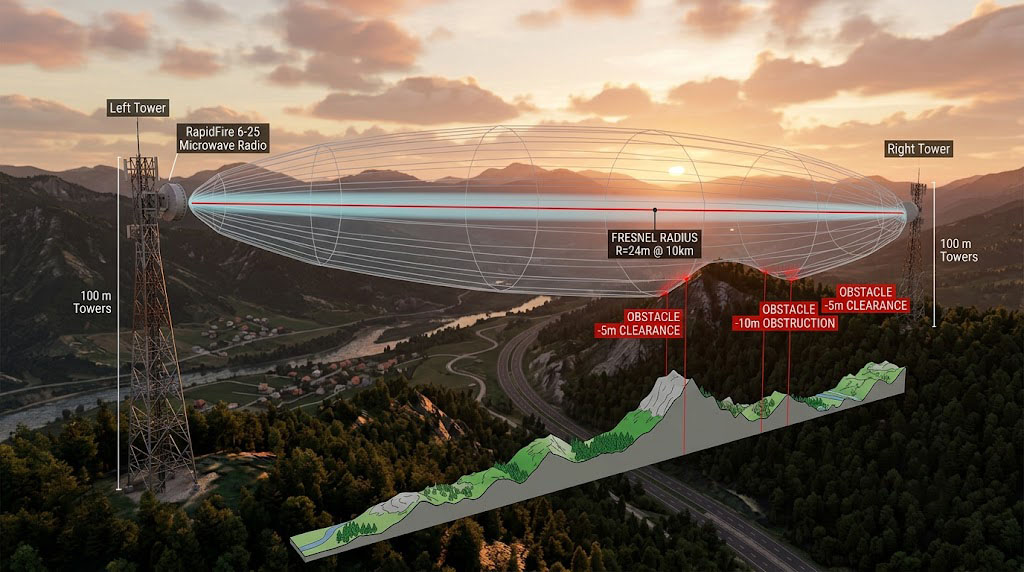
The Fresnel zone is an ellipsoid between the transmitter and receiver where most of the signal energy travels. If anything — ground, buildings, hills, trees — sticks into that zone, your signal takes a measurable hit.
First Fresnel Zone Radius:
r = 8.656 × √(d / 4f)
Where d = total distance (km), f = frequency (GHz), r = radius (m).
40km link @ 6GHz:
r = 8.656 × √(40 / 24) = 8.656 × √1.667 = 8.656 × 1.291 = 11.2 m

100km link @ 6GHz:
r = 8.656 × √(100 / 24) = 8.656 × √4.167 = 8.656 × 2.041 = 17.7 m
Fresnel Clearance Requirement: In practice, you want 60%+ of the first Fresnel zone clear. For that 40km link, antennas need to be high enough so nothing blocks the 11.2m radius at the midpoint.
Fresnel Clearance Check Steps:
- Mark exact lat/lon of both sites in Google Earth Pro
- Draw the straight-line path between endpoints
- Pull elevation data along the path using the elevation profile tool
- Calculate the Fresnel radius at the highest midpoint
- Derive minimum antenna height: tallest obstacle + Fresnel radius
- Determine minimum mounting height at both ends
Pro tip: For 50km+ links, don’t ignore the earth’s curvature. On the regulatory side, 6GHz deployments should follow [FCC 47 CFR Part 15] and [FCC 20-51] for TX power and spectrum use limits within the unlicensed framework.
Earth curvature drop h = d² / (2R)
where d = distance from nearest endpoint, R ≈ 6371 km (earth radius)
At the midpoint of a 40km link:
h = (20km)² / (2 × 6371km) = 400 / 12742 km = 0.0314 km = 31.4 m
Even with flat terrain, antennas need enough height to clear that curvature. That’s why ultra-long-range links almost always end up on tall towers, hilltops, or rooftops.
2.3 Site Selection Checklist
[ITU-R P.525] (FSL), [ITU-R P.530-18] (LOS link design), [ITU-R P.526-13] (diffraction), and [ITU-R P.838-3] (rain attenuation). A 100km@6GHz link can hit 19dB fade margin with a 17.7m Fresnel radius requiring 60%+ clearance.
| Factor | Requirement | Notes |
|---|---|---|
| Line of Sight | 60%+ Fresnel zone clear along path | Analyze with Google Earth Pro or professional link tools |
| Antenna Height | Minimum Fresnel clearance | Combine Fresnel radius + earth curvature + obstacle height |
| Structural Load | Antenna+radio weight + wind safety margin | Large dishes (1.8m+) can see 100kg+ wind load |
| Power | PoE (42–57VDC) at device end | Solar + battery is an option |
| Grounding | Dedicated ground system, resistance <10Ω | Foundation for lightning protection |
| Network Backhaul | At least one link to a local switch | Connect RapidFire’s wired port to LAN |
| Service Access | Antenna position must be safely reachable | Tower ladder, lift, etc. |
| RF Environment | No strong interferers in target band | Confirm with a spectrum analyzer on site |
Antenna Selection & Installation
3.1 Understanding Antenna Specs
For RapidFire 6-N users (for a detailed comparison with the 6-25, see RapidFire 6-N vs 6-25: Full Comparison), the antenna is what makes or breaks your range. Focus on these parameters:
Gain (dBi): How well the antenna focuses RF energy in a specific direction. In long-range links, chasing high gain means:
- Every 3dB of added gain is like doubling your TX power
- But higher gain means a narrower beam
Beamwidth (°): Half-power beamwidth (HPBW) tells you how forgiving the alignment is:
- 30dBi antenna (1.2m dish): ~6°–8° HPBW
- 35dBi antenna (1.8m dish): ~4°–6° HPBW
- 38dBi antenna (2.4m dish): ~3°–4° HPBW
Every time beamwidth halves, alignment precision has to double. At 100km, a 1° misalignment means a ~1.7km offset at the far end — making precision aiming the toughest part of ultra-long-range deployments.
Front-to-Back Ratio (F/B, dB): Measures how well the antenna rejects interference from behind. Important when multiple antennas share a tower — aim for >30dB.
Polarization: RapidFire uses 2×2 MIMO, so you need a dual-polarized antenna (V/H or ±45°). If you use single-pol antennas, you’ll need two of them, one per RF port.
3.2 Antenna Recommendations by Range
| Range | Recommended Type | Typical Gain | Beamwidth | Notes |
|---|---|---|---|---|
| 10–20km | Panel antenna | 25–28dBi | 10°–15° | Low cost, easy install |
| 20–40km | 0.6m grid dish | 28–31dBi | 6°–10° | Lightweight, low wind load |
| 40–80km | 1.2m solid dish | 31–34dBi | 5°–8° | Stable performance, needs sturdy mount |
| 80–150km | 1.8m solid dish | 34–37dBi | 4°–6° | Professional install, precision alignment |
| 150–300km | 2.4m+ solid dish | 37–42dBi | 3°–5° | Extreme range, major engineering effort |
Solid vs Grid Dish: At 6GHz (for a deep dive into the 6GHz band and W-Jet V protocol, see 6GHz Band & W-Jet V Protocol: Deep Dive), skip grid antennas. The wavelength is too short — grid gaps cause performance loss. Solid dishes deliver far better efficiency and stability at this frequency.
3.3 Antenna Installation Essentials
Mounting:
- Every antenna goes on a stable mount or tower
- The mount must handle the antenna’s weight plus maximum expected wind load
- Use stainless steel or hot-dip galvanized hardware to avoid corrosion
Precision Alignment Procedure:
- Rough aim: Use a compass and inclinometer to point the antenna at the far end
- Open alignment tool: Connect via laptop or phone to the RapidFire’s 2.4GHz management WiFi, open the antenna alignment page in the Web GUI
- Read RSSI: Watch the RSSI value and RGB LED indicators (1dBm step resolution)
- Horizontal sweep: Slowly rotate the antenna horizontally, find the RSSI peak, mark the angle
- Vertical sweep: Fine-tune elevation once horizontal is locked
- Lock it down: Tighten all bolts at the RSSI peak position
- Verify: Re-check RSSI after tightening — make sure nothing shifted
With a 35dBi antenna (5° beamwidth), each adjustment step should be 0.5° or less. A high-precision pan/tilt mount makes this a lot more manageable.
RapidFire Setup & Configuration
4.1 Hardware Installation
The RapidFire mounting bracket works with standard communication tower pipes and poles.
Installation Steps:
- Secure the bracket to the pole, make sure it’s level
- Mount the RapidFire unit on the bracket (orient the handle for easy access)
- Connect the feed cable (6-N model) or mount directly (6-25 model)
- Connect the Ethernet cable (from PoE injector to the unit)
- Power on the PoE injector
Lightning & Grounding:
- The device body grounds through the mounting bolt to the tower ground system
- Feed line shield grounds at both ends (tower top and building entry)
- The PoE injector must include surge protection (RapidFire’s standard injector has it built in)
- Install a feed-line surge arrestor before the cable enters the building
4.2 First-Time Configuration
Method 1: Via 2.4GHz Management WiFi (recommended)
- Power up the device, search for WiFi on your phone or laptop
- Connect to the “YNWPTP-XXXX” or “RapidFire-XXXX” SSID (password on the device label)
- Open a browser, go to 192.168.1.1 (default management IP)
- Default username/password: admin/admin (change it immediately after first login)
Method 2: Wired Configuration
- Connect your PC’s Ethernet port to the PoE injector’s DATA port
- Set your PC to the 192.168.1.x subnet
- Navigate to 192.168.1.1 to access the management interface
Initial Configuration (using the setup wizard):
- Select operating mode: Master or Slave
- Set wireless parameters: channel bandwidth (40MHz or 80MHz recommended)
- Configure RF parameters: TX power, frequency/channel selection
- Configure network settings: IP address, subnet mask, default gateway
- Set the admin password
- Apply config and reboot
One-Side Config Sync (RapidFire’s unique advantage):
- Complete all parameter configuration on the Master
- Enable “one-side config sync” in the settings
- Power on the Slave — the Master automatically pushes the config
- The Slave applies the parameters and reboots
- The link comes up automatically
Note: One-side sync requires both Master and Slave to be at factory defaults or pre-paired. If the Slave was configured separately, factory reset it first.
4.3 Link Optimization
Once the link is up, run through these steps for best performance:
1. Fine-Tune Alignment
- Watch the RSSI reading on the antenna alignment page
- Micro-adjust the antenna angle for the peak RSSI
- Target: RSSI fluctuation < 1dBm
- Log the optimal RSSI value
2. Channel Optimization
- Run the built-in spectrum analyzer (5-minute sweep)
- Confirm the selected channel has no strong interference
- Switch to an alternate channel if needed
3. Throughput Test
- Use iperf or the device’s built-in throughput test tool
- Test bidirectional throughput (TCP and UDP)
- Measure latency and jitter (run for 5 minutes minimum)
- Compare against the link budget prediction
4. Baseline Documentation
Record these baseline metrics for future reference:
| Parameter | Measured Value | Notes |
|---|---|---|
| RSSI | -52 dBm | Target range: -30 to -70 dBm |
| SNR | 38 dB | Higher is better; >25dB is good |
| Link Rate | 780 Mbps | Adaptive modulation negotiated rate |
| TCP Throughput | 650 Mbps | Bidirectional (5-minute test recommended) |
| Latency | 3 ms | One-way over-the-air delay |
| Jitter | <0.5 ms | Variation in latency |
Deployment by Range
5.1 Short Range (1–10km)
Characteristics: Plenty of fade margin, minimal setup complexity.
- Best choice: RapidFire 6-25 (integrated design)
- Even at minimum bandwidth (20MHz), performance is solid
- Wide alignment tolerance
- Works as a PtMP slave or access node
Simplified Deployment:
- Ground-level mounting works — no tower needed
- PoE range: up to 100 meters
- One-side config sync gets it done in minutes
5.2 Medium Range (10–40km)
Characteristics: Fresnel zone matters, but integrated antennas still work.
- The RapidFire 6-25 performs best in this range
- 25dBi antenna + 30dBm TX power = 10–20dB fade margin
- LOS is required — run a Google Earth Fresnel analysis
- Antenna height may need 20–50m depending on terrain
5.3 Long Range (40–100km)
Characteristics: Must use RapidFire 6-N + high-gain antenna. Needs careful planning.
- Recommended: 1.2m–1.8m dish (30–35dBi)
- Minimize cable loss — mount the RF unit close to the antenna, keep cable runs <3m
- Earth curvature is significant — antenna height may need 50–150m
- Use 40MHz channel bandwidth (instead of 80MHz) for better interference immunity
- Target fade margin: >15dB
Pre-Deployment Checklist:
- Google Earth Fresnel analysis confirms 60%+ clearance
- Link budget confirms fade margin >15dB
- On-site spectrum scan confirms no interference on selected channel
- Antenna mount structural integrity verified (including max wind load)
- Lightning protection system accepted
- 2.4GHz management WiFi reachable at both ends
- Spare parts ready (backup unit, connectors, tools)
5.4 Ultra-Long Range (100–300km)
Characteristics: Extreme challenge. Requires major project-level planning and investment.
- Must use RapidFire 6-N + 1.8m–2.4m+ dish
- Site selection is the single most important factor
- Requires astronomical-grade azimuth and elevation calculations
- Fade margin may be as low as 5–15dB — weather has a real impact
- Use 20MHz or 30MHz channel bandwidth to maximize link stability
- May need relay stations (multi-hop)
Engineering Requirements:
- Professional site survey: Use RTK GPS or total station for precise coordinates
- Antenna installation: Professional team with laser alignment tools
- Climate assessment: Analyze year-round wind, rainfall, and temperature data
- Backup plan: At least one alternate site or path
- Relay consideration: 100km+ usually needs a relay. RapidFire’s dual-port design supports this natively
Relay Configuration: With RapidFire’s PoE passthrough and dual ports, a relay station needs just two units back-to-back:
Site A (Master) ←→ Relay (Slave + Master) ←→ Site B (Slave)
The beauty of this setup: the relay doesn’t need extra switching gear. The PoE passthrough port powers both units from a single injector.
Link Monitoring & O&M
6.1 Key Monitoring Metrics
| Metric | Normal Range | Alert Threshold | Action |
|---|---|---|---|
| RSSI | -30 to -70 dBm | < -75 dBm (below 256-QAM threshold) | Check alignment, weather, interference |
| SNR | > 25 dB | < 20 dB | Check for interference, try changing channel |
| Link Rate | Adaptive (AMC) | Consistently below 50% of rated speed | Review link budget, check for hardware issues |
| CPU Utilization | < 60% | > 80% (sustained 5 min) | Check for broadcast storm or DoS |
| Temperature | -40 to +65°C | > +70°C | Check cooling, sun shielding |
| Packet Loss | < 0.01% | > 0.1% | Check interference, connections, CRC errors |
6.2 Common Troubleshooting
Scenario 1: Link Won’t Establish
- Verify both units are powered on (check PoE injector LEDs)
- Check that the management WiFi is reachable (2.4GHz radio)
- Log into the Web GUI and check wireless status — Master/Slave roles correct?
- Check RF parameters — channel, bandwidth, frequency match on both ends?
- Check antenna alignment — is RSSI a valid reading (>-85dBm)?
Scenario 2: Throughput Lower Than Expected
- Check the link rate — is it running on a high-order modulation?
- Check SNR — is it > 25dB?
- Run a spectrum analysis — new interference?
- Check the wired port — negotiated to 1000Mbps (full duplex)?
- Check CPU utilization — processing bottleneck?
Scenario 3: Intermittent Disconnects
- Check PoE power stability (voltage dips can cause reboots)
- Check weather records — does it correlate with bad weather?
- Check antenna stability in strong wind (is it swaying?)
- Review link logs — excessive CRC errors or retransmissions?
6.3 O&M Best Practices
- Firmware Management:
- Stay on the latest official stable release
- Back up config before any firmware upgrade
- Dual firmware image reduces upgrade risk (rollback if needed)
- Log Management:
- Configure Syslog to forward logs to a central server
- Configure SNMP Trap alerts (tie into your NMS)
- Keep at least 30 days of log history
- Regular Inspection:
- Monthly: check device status and link performance
- Quarterly: run a full-band spectrum scan
- Yearly: on-site inspection (tighten bolts, check weather seals, clean antenna surface)
- Spares Management:
- Critical links should have a full replacement unit on hand
- Stock feed cables, connectors, waterproof tape
- Keep serial numbers and config backups documented
Case Studies
Case 1: 80km Sea-Crossing Backbone (Dec 2024 · Zhoushan, Zhejiang)
Scenario: A resort island in the Shengsi archipelago needed a high-speed data link back to the mainland headquarters in Beilun, Ningbo — video surveillance backhaul, office network, VoIP. Submarine fiber was prohibitively expensive. Per the [IHS Markit Industrial Wireless Survey 2024], roughly 73% of enterprises facing similar cross-water connectivity needs turn to wireless when fiber costs and timelines are too high.
Solution:
- One RapidFire 6-N at each end
- 1.2m dual-pol dish (32dBi each)
- Mainland site: 80m tower on a hilltop
- Island site: 40m self-supporting tower on a ridge
- Channel bandwidth: 40MHz
- Expected throughput: 400Mbps
Results:
- Measured RSSI: -58dBm
- Fade margin: 13dB
- Actual throughput: 380–420Mbps (bidirectional)
- Latency: 4ms
- 12-month availability: 99.8% (only two outages during typhoons)
Case 2: 180km Mountain Relay Link (May 2025 · Southwest Sichuan Oil & Gas Field)
Scenario: An oil pipeline monitoring system needed to aggregate data from 15 monitoring stations along a 180km pipeline to a central control room. The terrain is mountainous. Building private fiber was quoted at $1.25 million.
Solution:
- 4 relay hops, each 40–50km
- Relay hops: RapidFire 6-N + 1.2m dish
- End access: RapidFire 6-25
- Relay stations powered by solar + battery
Results:
- Total build cost: ~$62,000 (all equipment and towers included)
- Per-hop throughput: 450–550Mbps
- End-to-end latency: ~20ms (4 hops)
- SCADA data collection and video surveillance all running smoothly
Conclusion
Deploying an ultra-long-range RapidFire link is a systematic effort. Success comes down to:
- Scientific planning — accurate link budget, Fresnel analysis, site survey
- Right hardware choice — 6-N or 6-25, based on distance and flexibility needs
- Precision installation — especially high-gain antenna alignment
- Complete lightning protection — critical for long-term reliability
- Ongoing monitoring — maintaining performance as conditions change
When all these pieces are in place, RapidFire delivers stable, high-throughput wireless backhaul at 100km+ ranges — a genuine alternative for sites where fiber can’t go or costs too much.
[IHS Markit Industrial Wireless Survey 2024], 73% of enterprises choose wireless for cross-water connectivity.
Further Reading:
- RapidFire 6-N vs 6-25: Full Comparison — Key differences between the two RapidFire models
- Industrial Wireless Bridge Installation & Deployment Best Practices — Complete installation procedures and acceptance criteria
- Rural Broadband Last Mile & Multi-Building Campus Connectivity — Long-range links for rural and campus scenarios
References
- ITU-R P.525-4 — Calculation of free-space attenuation. International Telecommunication Union, 2019.
- ITU-R P.530-18 — Propagation data and prediction methods required for the design of terrestrial line-of-sight systems. ITU, 2021.
- ITU-R P.526-13 — Propagation by diffraction. ITU, 2013.
- ITU-R P.838-3 — Specific attenuation model for rain for use in prediction methods. ITU, 2005.
- FCC 47 CFR Part 15 — Radio Frequency Devices. Federal Communications Commission.
- FCC 20-51 — Unlicensed Use of the 6 GHz Band. FCC, 2020.
- IHS Markit — Industrial Wireless Survey 2024: Connectivity Trends in Oil & Gas and Maritime Industries.
- YNWPTP RapidFire 6-N / 6-25 — Product Datasheets and Technical Manuals, YNWMICRO, 2025.
Frequently Asked Questions (FAQ)
Q: What’s the single most important success factor for an ultra-long-range RapidFire link?
Based on field experience, ranked by importance: site selection (ensuring 60%+ Fresnel zone clearance) > accurate link budget calculation (target margin >15dB) > precision antenna alignment (<0.5° accuracy) > lightning grounding. Site selection is the most overlooked but most impactful — a proper Fresnel analysis using Google Earth Pro can prevent 80%+ of post-deployment performance issues. On a 100km link, just 5m of Fresnel intrusion can cost you 6–10dB of signal attenuation, dropping you a full MCS level.
Q: What size antenna do I need for a 100km+ link?
For 100km+ ranges, go with a 1.8m–2.4m solid dish (34–42dBi gain). Specifically: 100–150km needs a 1.8m dish (34–37dBi); 150–300km needs a 2.4m+ dish (37–42dBi). Keep in mind that high-gain antennas come with very narrow beamwidth — a 38dBi antenna has a 3°–4° beamwidth. At 100km, a 1° misalignment translates to roughly 1.7km of offset. You’ll need a high-precision pan/tilt mount with fine adjustment mechanisms.
Q: What metrics should I monitor for long-term RapidFire link O&M?
Focus on four metrics: RSSI, SNR, link rate, and packet loss. Healthy ranges: RSSI between -30 and -70 dBm, SNR >25dB, packet loss <0.01%. Set up SNMP Trap alerts for when RSSI drops below -75dBm, SNR falls under 20dB, or packet loss exceeds 0.1%. Run a full-band spectrum scan quarterly to catch new interference. Do an on-site inspection annually — tighten bolts, check weather seals, clean antenna surfaces.
Q: How do I choose between the RapidFire 6-N and 6-25 for long-distance deployment?
The 50km mark is the dividing line. Within 50km LOS, the YNWPTP 6-25 RapidFire (integrated 25dBi antenna) is the better choice — zero RF cable loss, 15–30 minute deployment, lower 5-year TCO. Beyond 50km, you need the YNWPTP 6-N RapidFire paired with a 30dBi+ external dish. Key difference: the 6-25’s integrated 25dBi antenna hits its fade margin limit (~13–23dB) at 50km, while the 6-N with 30dBi+ antennas maintains a comfortable 10–20dB margin even on 60–80km links.
Performance Disclaimer: Link budget, throughput, and coverage figures in this article are based on theoretical calculations and standard lab conditions. Real-world performance varies with antenna configuration, installation height, weather, and RF environment. Product specs are subject to change per YNWMICRO’s latest official documentation.
Certifications: YNWMICRO wireless bridges are certified under FCC (47 CFR Part 15), CE (EN 301 893), SRRC, and others. Contact sales for certification document copies.
This document is a technical reference guide. Always follow local regulations and secure frequency-use authorization where required.


