Maritime Rescue & Ship Squadron Communication Solution: 1.4G Mesh Anti-Multipath Beyond-Line-of-Sight Networking, 50–150km
At-a-Glance Overview
Who this article is for: maritime search-and-rescue centers, maritime-emergency agencies, maritime-law-enforcement and warship-squadron management departments, and ocean-engineering / ship navigation-and-communications system integrators — any organization that needs to build a broadband private network between ships in remote seas with no public network.
Core problem: at sea there is no public network, wide-open areas with little occlusion yet strong multipath and Doppler; conventional broadband cannot reach beyond line of sight. A ship squadron needs an interference-resistant, multipath-resistant, infrastructure-free broadband link between ships and between the flagship and shore. Satellite can connect, but at expensive bandwidth and high latency — it cannot support multiple HD video streams and low-latency real-time data exchange within a squadron.
Core conclusion: a complete maritime rescue & ship squadron communication solution combines the airborne (P2) + backpack (P1) + command platform (P3) to build a ship-squadron ad-hoc network on the 1.4GHz private band: COFDM + MIMO 2×2 resists sea-surface multipath and Doppler shift, multi-hop relays extend reach to 50–150km, the flagship links to shore via satellite, and the failure of any single node does not affect the squadron network. The private network carries high-frequency video/data within the squadron, while satellite only handles the “squadron-to-shore” aggregated uplink — each does its own job, minimizing cost and bandwidth.
Solution Overview: What Problem Does It Solve, and for Which Scenarios?
1.1 Construction Background
The communication needs of maritime operations and emergencies (open-ocean escort, maritime search and rescue, offshore oil-and-gas inspection, fisheries management, coast-guard enforcement) are growing, yet every conventional communication method has clear shortcomings at sea:
- No public network: beyond 10–20km offshore there is no carrier coverage; between fleets and between ship and shore, only a private network or satellite is usable.
- Beyond-line-of-sight bottleneck: the sea is wide open, but Earth’s curvature limits line of sight — two ships with masts about 10m high have a direct line-of-sight range of only about 20km, so a squadron tens of kilometers deep is “out of sight.”
- Multipath and Doppler: the sea acts like a mirror with strong reflection, causing multipath fading; ship motion adds Doppler shift, and ordinary broadband is unstable at sea.
- Satellite limitations: bandwidth is expensive (Mbps grade) and latency is high (hundreds of milliseconds), unsuited to multiple HD video streams and low-latency real-time data exchange within a squadron.
The maritime rescue & ship squadron communication solution centers on this idea: deploy 1.4GHz wideband Mesh ad-hoc equipment aboard each ship and on airborne platforms, let every ship become a mobile node in the network, reach beyond-line-of-sight broadband interconnection through multi-hop relays, and have the flagship link to shore via satellite — forming a “private network within the squadron + satellite for squadron-to-shore” division of work.
1.2 Applicable Scenarios
- Ship squadron collaboration: collaborative missions that keep changing formation, such as open-ocean escort, joint patrol and formation navigation
- Maritime search and rescue: wreck search-and-rescue, locating persons in the water, rescue-boat and helicopter coordination
- Ocean engineering: offshore oil-and-gas platform communication, subsea pipeline inspection, marine environment monitoring
- Maritime law enforcement: coast-guard enforcement, fisheries control, maritime anti-smuggling
- Emergency communication: communication recovery after typhoons, temporary networking at the scene of a major maritime accident
1.3 Solution Objectives
| Objective Dimension | Specific Target |
|---|---|
| Beyond-line-of-sight breakthrough | Multi-hop relays extend squadron depth to 50–150km |
| Multipath/Doppler resistance | COFDM + MIMO 2×2 diversity, stable transmission up to sea state 4 |
| Broadband carriage | 70–120Mbps per hop, supporting 1080P/4K video, flight-control commands and sensor data |
| Network self-healing | Single-node failure re-routes automatically in ≤ 100ms; squadron network never drops |
| Platform compatibility | Compatible with mast mounting on all ship types + ship-based UAVs + portable soldier terminals |
| Security & compliance | AES-256 encryption, cipher-machine integration supported, meeting maritime communication security requirements |
Citation capsule: The core of the maritime rescue & ship squadron solution is to deploy 1.4GHz wideband Mesh ad-hoc equipment aboard each ship and on airborne platforms, letting each ship become a mobile node and achieving beyond-line-of-sight broadband interconnection through multi-hop relays (target depth 50–150km), with the flagship linking to shore via satellite. Sub-targets: COFDM+MIMO 2×2 resists sea-surface multipath and Doppler, 70–120Mbps per hop, ≤100ms self-healing on single-node failure, AES-256 encryption. [IEEE 802.11s] provides the multi-hop self-healing routing basis for this ad-hoc network.— Overview of the maritime ship-squadron ad-hoc solution
Maritime Communication’s “Triple Difficulty”: No Public Network, Beyond Line of Sight, Multipath/Doppler
Difficulty 1: No Public Network
Beyond the shore base there is no carrier coverage. Between fleets and between ship and shore, only a private network or satellite is usable. Satellite does cover remote seas, but its bandwidth is expensive (commercial Ku/Ka on-the-move is usually a few Mbps to tens of Mbps), latency is high (a GEO hop is about 250–300ms), and it cannot support multiple HD video streams and low-latency real-time data exchange within a squadron.
Difficulty 2: Beyond Line of Sight
The sea is wide open, but straight-line line of sight is bounded by Earth’s curvature. By the classic antenna line-of-sight formula d ≈ 4.12 × (√h₁ + √h₂) (d in km, h in m), two ships with masts about 10m high have a direct line of sight of only about 26km [ITU-R P.526 defines the evaluation method for in-sight diffraction and Huygens propagation. ITU-R P.530 provides the engineering basis for ground propagation path loss and line-of-sight computation]. If the antenna is mounted on a 5m-high deck, line of sight shortens to about 18km. If ships are tens of kilometers apart they are “out of sight” — no matter how flat the sea is, the Earth is round.
Difficulty 3: Multipath/Doppler
The sea is like a mirror with strong reflection, causing multipath fading; ship motion adds Doppler shift, and ordinary broadband is unstable at sea. These three difficulties overlay to make the sea one of the most “treacherous” broadband communication environments.
What a ship squadron truly needs is a wideband private network that is free of terrestrial public networks, multipath-resistant, supports multi-hop beyond line of sight, and can flexibly come and go — precisely where ad-hoc networking finds its use at sea. It is not “stealing the satellite’s job” but dividing work with satellite: high-frequency video/data inside the fleet is carried on the private network, while slow aggregated cross-ocean / shore-bound traffic is given to satellite — each does its own job.
Citation capsule: The three difficulties of maritime broadband are: no public network (no carrier coverage 10–20km offshore), beyond line of sight (Earth’s curvature limits the view; two ships with masts 10m high have direct line of sight of only about 26km, per ITU-R P.526/P.530), and a weakened signal (sea-surface mirror reflection causes multipath fading, ship motion introduces Doppler shift). A ship squadron therefore needs a wideband private network that is free of public networks, multipath-resistant and supports multi-hop beyond line of sight, dividing work with satellite.— Maritime communication’s “triple difficulty” and the ad-hoc solution
The Physical Roots of Sea-Surface Multipath and Doppler: Why the Sea Is “More Treacherous” Than Land
Maritime communication difficulties concentrate at the physical layer and are “more treacherous” than on land because the sea has no buffer of any kind:
Multipath Fading: The Sea Is Like a Mirror
The sea surface is like a mirror; the direct wave and the reflected sea-surface wave superpose at the receiver. The phase difference between the two varies continuously with path difference, and peaks and troughs alternate to make the signal surge and fade — this is frequency-selective fading. The worse the sea state and the higher the waves, the more “fragmented” the reflecting surface and the more complex the fading; short deep fades can swallow an entire data block.
Unlike land multipath, the sea-surface reflection coefficient is extremely high (close to 0.9 on a calm sea); direct and reflected wave powers are similar, and fade depth can reach 20–40dB — far above the typical values of urban-land multipath. Thus the maritime link budget must reserve a larger fade margin.
Doppler Shift: Ship Motion + Antenna Rocking
Ships and airborne nodes move toward and away at high relative speed, “stretching” the frequency. At 1.4GHz, a relative speed of 30 knots (about 55km/h) produces a Doppler shift of about 72Hz; if two ships move toward each other it adds to roughly 144Hz. A rocking ship also keeps changing the antenna pointing, further magnifying frequency offset and gain jitter. Unless the system compensates effectively, carrier synchronization drifts and the bit-error rate spikes.
Fresnel Zone: Height Determines Distance
Beyond line of sight, raising the antenna height is the way to enlarge the effective link. The first-Fresnel-zone radius is inversely proportional to frequency — the 1.4GHz Fresnel-zone radius is about twice that of 5.8GHz, meaning the low band tolerates more sea-surface obstruction. Mast height and airborne height directly determine how far a single hop can cover.
Countermeasures: COFDM + Low Band + MIMO Diversity
| Countermeasure | Technical Principle | Effect at Sea |
|---|---|---|
| COFDM subcarrier diversity | Splits the wideband into hundreds of narrow orthogonal subcarriers; each subcarrier undergoes flat fading rather than frequency-selective fading | “Flattens” sea-surface frequency-selective multipath onto individual subcarriers, preventing an entire data block from being swallowed by deep fading [ETSI EN 300 744] |
| Cyclic prefix (CP) | Inserts a guard interval at the start of every OFDM symbol to absorb multipath delay spread | The delay difference between the sea direct wave and the reflected wave is absorbed by the CP, eliminating inter-symbol interference (ISI) [ETSI EN 300 744] |
| Low band 1.4GHz | Longer wavelength (about 21cm), stronger diffraction, longer symbol period | More stable propagation, farther coverage, and higher tolerance to Doppler shift than high bands |
| MIMO 2×2 diversity | Dual-antenna transmit + dual-antenna receive, spatial diversity combining | The probability that two independent fading paths both deep-fade at once is very low, further hedging sea-surface deep fading [IEEE 802.11n] |
| Higher antenna | Raising antenna height improves Fresnel-zone clearance | Mast mounting or airborne lift-off dramatically enlarges the single-hop line-of-sight geometry |
The equipment series is built on COFDM + MIMO 2×2, using diversity combining to further hedge deep fading [ETSI EN 300 744][IEEE 802.11n], a natural fit for scenes where the signal is “shredded” at sea. By contrast, ordinary single-antenna OFDM or DSSS equipment tends toward “intermittent link loss” under sea-surface deep fading, while the COFDM + MIMO combination compresses the “link-loss probability” to an engineering-acceptable level.
Citation capsule: Why sea-surface multipath and Doppler are “more treacherous” than on land: on a calm sea the reflection coefficient is close to 0.9, direct and reflected wave powers are similar, and deep fading can reach 20–40dB; at 1.4GHz a 30-knot relative speed produces a Doppler shift of about 72Hz, compounding to about 144Hz on approaching courses. Countermeasures are COFDM subcarrier diversity + cyclic prefix (ETSI EN 300 744) absorbing multipath delay, MIMO 2×2 (IEEE 802.11n) hedging deep fading, and the 1.4GHz low band lengthening the symbol period for higher Doppler tolerance.— Physical roots of sea-surface multipath/Doppler and countermeasures
Band Selection Comparison: Why 1.4G Is the Optimal Choice for a Maritime Private Network
| Comparison Dimension | 1.4GHz Private | 2.4G/5.8G Civil | 5G Public | Satellite (Ku/Ka) |
|---|---|---|---|---|
| Wavelength | About 21cm | 12cm / 5cm | About 3–6cm | About 2–3cm |
| Sea-surface diffraction | Strong, large Fresnel-zone radius | Weak, sensitive to sea occlusion | Weak | N/A (line-of-sight feed) |
| Doppler tolerance | High (long symbol period) | Low | Medium (needs high-mobility mode) | High (but needs tracking antenna) |
| Maritime coverage | Single-hop line of sight 8–15km | 1–5km | 1–10km (depends on shore station) | Global coverage |
| Bandwidth | 70–120Mbps | 30–100Mbps | 100Mbps+ (shared) | 1–50Mbps |
| Latency | 30–120ms | 10–50ms | 10–40ms | 250–600ms |
| Infrastructure dependency | None, meshes on power-up | None | Needs shore-base stations | Needs satellite + core network |
| Multipath resistance | Strong with COFDM + MIMO | Weak (civil OFDM) | Medium | N/A |
| Cost | Medium (one-time equipment) | Low | Medium (data fee) | High (terminal + traffic) |
| Compliance | Licensed private network, needs regulatory approval | License-exempt ISM [FCC 47 CFR Part 15] | Carrier licensed | Satellite-operator licensed |
Conclusion: 1.4GHz is comprehensively optimal across the five dimensions of “coverage distance, diffraction capability, Doppler tolerance, multipath resistance and no infrastructure dependency.” 5G and satellite each have their place, but 5G covers only near-shore areas and depends on shore stations, while satellite has high latency and expensive bandwidth — they complement, not replace, 1.4G Mesh. Commercial projects are recommended to adopt the “1.4G Mesh primary + 5G/satellite secondary” hybrid backup model.
Citation capsule: 1.4GHz (wavelength about 21cm) is the optimal maritime private-network band: versus the 2.4G/5.8G civil bands (power-limited by FCC 47 CFR Part 15, wavelengths 12/5cm) it has larger sea-surface diffraction and Fresnel-zone radius and a longer symbol period, hence higher Doppler tolerance; versus 5G public (near-shore only, depends on shore stations) and satellite (latency 250–600ms, expensive bandwidth) it is infrastructure-free, offers 70–120Mbps, and 30–120ms latency. Recommended: the “1.4G Mesh primary + 5G/satellite secondary” hybrid backup model.— The 1.4G maritime private-network band-selection basis
Link Budget and Coverage Analysis: How Far Can a Single Hop Reach?
Line-of-Sight Calculation
Sea-surface line of sight is bounded by Earth’s curvature; the classic formula is d ≈ 4.12 × (√h₁ + √h₂) (d in km, h in m) [ITU-R P.526][ITU-R P.530].
| Scenario | Antenna 1 Height | Antenna 2 Height | Theoretical Line of Sight |
|---|---|---|---|
| Two-ship mast-to-mast | 10m | 10m | About 26km |
| Ship mast to ship deck | 10m | 5m | About 22km |
| Ship mast to airborne 100m | 10m | 100m | About 54km |
| Ship mast to airborne 300m | 10m | 300m | About 87km |
| Airborne 300m to airborne 300m | 300m | 300m | About 143km |
Link Budget Estimate (1.4GHz, P1 to P1)
| Budget Item | Value | Note |
|---|---|---|
| Transmit power | 33dBm (2W) | P1 backpack-rated power |
| Transmit antenna gain | 6dBi | Omnidirectional vertically polarized antenna |
| Receive antenna gain | 6dBi | Same as above |
| System gain | 45dBm | 33 + 6 + 6 |
| Receiver sensitivity | -95dBm | In 70Mbps@20MHz mode |
| Allowable path loss | 140dB | 45 – (-95) |
| Free-space loss (15km) | About 119dB | 1.4GHz @ 15km |
| Sea-surface multipath fade margin | -15dB | Sea-surface reflection deep-fade reserve |
| Feed and connector loss | -2dB | Coaxial cable + waterproof connectors |
| Residual margin | About 4dB | 140 – 119 – 15 – 2 |
Conclusion: at 1.4GHz the P1-to-P1 link can retain about 4dB margin over a 15km single hop on the sea surface, meeting the engineering usability threshold. With a directional high-gain antenna (e.g., 12dBi), coverage rises to 20–25km. When the airborne P2 lifts to 100–300m, line of sight and link margin improve together, extending a single hop to 30–50km.
Citation capsule: The link budget determines the maritime single-hop range: taking the 1.4GHz P1-to-P1 link, a 2W transmit (33dBm) plus dual 6dBi antennas yields a system gain of 45dBm; subtracting the -95dBm receiver sensitivity gives an allowable path loss of 140dB; the 15km free-space loss is about 119dB, and after deducting a 15dB sea-surface multipath margin + 2dB feed loss only about 4dB remains. A 12dBi directional antenna extends reach to 20–25km, and the airborne P2 lifted to 100–300m reaches 30–50km per hop (line-of-sight formula per ITU-R P.526/P.530).— Maritime single-hop link budget and coverage analysis
Ship Squadron Networking Architecture: How to Achieve a Three-Layer Structure and Full-Network Self-Healing
| Role | Equipment | Responsibility | Key Capabilities |
|---|---|---|---|
| Flagship (coordination end) | Command platform (P3) / vehicle-mount | Squadron communication hub, large-screen dispatch, satellite-to-shore link | 4G/5G backhaul, GPS+BeiDou, visual dispatch, 14kg portable |
| Each ship (node end) | Backpack radio (P1) | One node per ship, auto-meshing and mutual relay | 120Mbps@40MHz, 64 nodes, IP67, 2W power amp, 6–12h endurance |
| Shipborne/airborne (high point) | UAV-carried MESH (P2) | Lifts off as a beyond-line-of-sight high point, crossing squadron distance | 70Mbps@20MHz, air-ground 10km+, 1.1kg, 2–4W |
| Soldier/small craft (edge) | Handheld radio (P5) | Edge access for rescue boats and boarding-inspection personnel | 90Mbps@20MHz, 1.2kg, IP66, 6h endurance |
The flagship deploys the P3 platform as the squadron center, each escort ship deploys a P1 backpack node, and a ship-based UAV (P2) takes off as a high-point relay. The airborne node stands out in “high point + flexible gap-filling”: when an escort ship is occluded by an island or a large hull, the P2 rises above the mast to break the geometric occlusion and bring the blocked ship into the network. Should the link between any two ships fail, data automatically routes around through other ships to rebuild the path — the squadron network “has no single point of failure,” precisely the maritime embodiment of ad-hoc self-healing [IEEE 802.11s defines the multi-hop routing and self-healing mechanism of a wireless Mesh]. Even if one ship’s radio fails outright, the network simply skips that node, the remaining ships continue to interconnect, and the squadron’s overall command is unaffected.
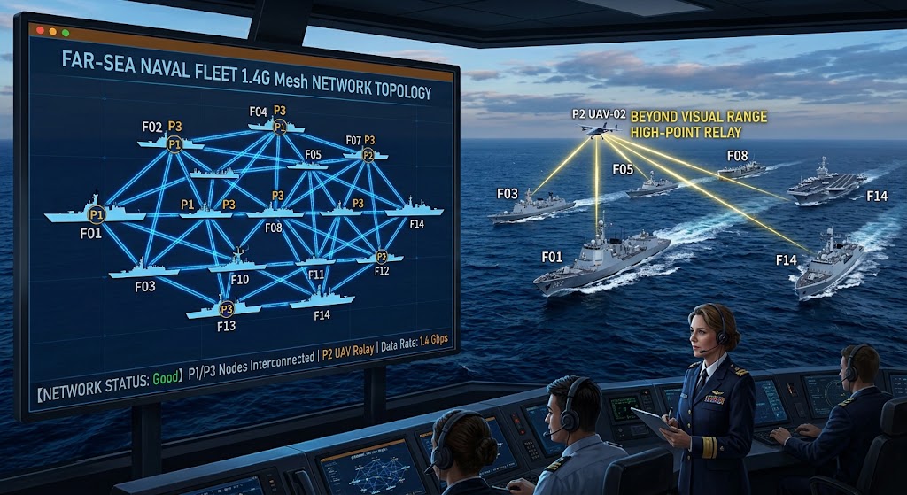
Fig. 1 | 1.4G Mesh for a remote-sea squadron: each ship deploys P1/P3 nodes meshing into one self-healing network, the P2 UAV lifts off between ships as a beyond-line-of-sight high-point relay, and the flagship command-cabin screen presents the entire squadron topology at a glance.
Citation capsule: Ship squadron networking is a three-layer structure with “one node per ship and full-network self-healing”: the flagship uses the P3 as the coordination hub and links to shore via satellite, each escort ship deploys a P1 backpack node that auto-meshes and mutually relays, the ship-based UAV P2 lifts off as a beyond-line-of-sight high point, and rescue boats/soldiers access at the edge via P5. When the link between any two ships fails, data routes around automatically through other ships to rebuild the path (IEEE 802.11s multi-hop self-healing), with no single point of failure and no central dependency; a single-node failure self-heals in ≤100ms.— The three-layer three-dimensional squadron networking architecture
How Near-Sea and Far-Sea Relay Extends Reach to 50–150km
At sea there is no mountain occlusion, but Earth’s curvature limits single-hop line of sight. The solution is the multi-hop link — every hop is bounded by “height” and “distance,” and stringing links together crosses beyond-line-of-sight depth:
In practice, the combination of “ship-to-ship + ship-to-aircraft + aircraft-to-shore” connects a squadron tens of kilometers deep into one network, far more than any single device’s straight-line coverage. It should be noted that depth extension costs bandwidth: each hop splits off part of the end-to-end bandwidth, so in a deep network the “backbone backhaul” should take the shortest reliable path, and high-flow services such as HD video should avoid crossing too many hops.
Citation capsule: With no mountain occlusion but single-hop line of sight limited by Earth’s curvature, “multi-hop relay” turns single-hop coverage into deep coverage: near shore use 0–30km ship–buoy–shore multi-stage point-to-point, mid-to-far sea 30–80km use 4–6 escort ships relaying ship by ship (10–15km × 4 hops ≈ 40–60km), and far sea 80–150km have the P2 airborne lift above 300m to stretch a single-hop line of sight to 50–80km as a “high-altitude springboard.” The trade-off: each hop splits off end-to-end bandwidth, so the backbone backhaul should take the shortest reliable path.— Near-sea and far-sea multi-hop relay extending to 50–150km
Flagship Coordination and Shore Connectivity: How Do the Private Network and Satellite Divide Work?
Maritime emergency response and command usually have two layers: real-time collaboration within the squadron + data linkage with the shore command center. The ad-hoc network covers the former, satellite/public network covers the latter, and the flagship becomes the convergence point of both and the squadron’s sole “external exit”:
| Layer | Carrying network | Service content | Bandwidth and latency |
|---|---|---|---|
| Within squadron (private) | 1.4G Mesh ad-hoc network | Real-time video, position, command and situational data exchange between ships | 70–120Mbps, 30–120ms |
| Squadron-to-shore (satellite) | Shipborne satellite (Ku/Ka) | Aggregated squadron situation uploaded to the shore command center | 1–10Mbps, 250–600ms |
| Backup link | 4G/5G (when near-shore coverage exists) | Public-network backhaul backup in near-shore areas | 10–50Mbps, 10–40ms |
Satellite carries only one “uplink” aggregated stream; dozens of HD streams inside the squadron stay on the private network, minimizing cost and bandwidth. The flagship’s value is not merely “accessing satellite” but “situation aggregation + unified exit”: it converges the raw data of 64 nodes into a single situation map reportable to shore, so the shore command center sees not 64 isolated streams but one picture of the entire squadron.
Data security: integration with cipher machines/encryption is supported, and AES-256 encryption protects sensitive video and commands within the squadron, guarding against private-network disclosure. The squadron is both a “closed ad-hoc network” and an “open offshore node,” combining both benefits.
Citation capsule: Maritime command adopts the “within-squadron private network + squadron-to-shore satellite” division of work: the 1.4G Mesh ad-hoc network carries HD video, position, command and situational data among 64 nodes within the squadron (70–120Mbps, 30–120ms); the shipborne satellite (Ku/Ka) carries only one aggregated situation uplink to shore (1–10Mbps, 250–600ms); 4G/5G acts as backup when near-shore coverage exists. The flagship is the “convergence point” of the two networks, converging 64 raw streams into one reportable situation map and applying AES-256 encryption to sensitive services.— Flagship coordination and the private-network + satellite division model
Two Topologies for Rescue/Squadron: Hub-and-Spoke or Chain/Mesh?
Mature ship-squadron ad-hoc solutions in the industry (such as the Tengyuan-Zhizhuo ship-squadron case, Jixiang Technology, and public ship/ocean-industry designs) generally adopt the “flagship + escort ships + airborne high point + satellite-to-shore” architecture, where the failure of any single node does not affect the squadron network. This solution differs by sinking the “backpack/handheld 1.4G Mesh” down to each ship and each rescue edge, so every ship and every rescue point can become a mobile node in the network rather than relying only on large shipborne stations — lower cost, faster deployment and broader coverage.
Citation capsule: Maritime networking divides into two topologies by mission objective: rescue leans toward “hub-and-spoke” (command ship centered, rescue boats/UAVs/edges converging, P3 dispatching at center, few hops and low latency), while squadron collaboration leans toward “chain/mesh” (ships as mutual nodes, flagship coordinating, airborne gap-filling, multi-hop data relay; when the squadron changes formation the nodes move with the ships and ad-hoc routing re-selects automatically without manual intervention). Mature industry solutions generally adopt the “flagship + escort ships + airborne high point + satellite-to-shore” architecture, and this solution further sinks the 1.4G Mesh down to each ship and each rescue edge.— Rescue hub-and-spoke vs squadron chain/mesh topology
Service Carriage: How Is Multi-Service QoS Prioritized?
| Service Type | Priority | Specific Content | Latency Requirement |
|---|---|---|---|
| Control signaling | Highest | Ship navigation commands, squadron coordination commands, emergency alarms | <200ms |
| Video services | High | Shipborne electro-optical/IR video streams, rescue-scene feeds (RTSP/RTMP) | 30–150ms |
| Situational data | Medium | AIS position, speed and heading, link SNR, radar data | 100–500ms |
| Voice dispatch | Medium | Two-way intercom between flagship and ships, cross-squadron trunking | <300ms |
| Extended services | Low | Weather data, marine monitoring data, file transfer | Non-real-time |
Citation capsule: The whole maritime network carries services by priority class: control signaling (navigation/squadron/emergency alarms) gets the highest priority <200ms, video services (shipborne electro-optical/IR, rescue-scene feeds) high priority 30–150ms, situational data (AIS position/speed/SNR/radar) and voice dispatch medium priority 100–500ms, and extended services (weather/monitoring/file) low priority non-real-time. QoS tiering ensures that control signaling and critical video are protected first when the sea state degrades or the network congests.— Maritime multi-service QoS-tiered carriage
Key Technical Specifications
| Specification | Parameter Value |
|---|---|
| Networking start-up time | Cold start ≤ 30s, hot start ≤ 5s |
| Routing self-healing switch time | ≤ 100ms (auto route rebuild when a node is lost) |
| Single-hop link distance | Sea-surface line of sight 8–15km; airborne 30–50km |
| Available bandwidth | P1 single node 120Mbps@40MHz; P2 single node 70Mbps@20MHz |
| End-to-end latency | 30–150ms (one to four hops) |
| Encryption standard | AES-256, frequency-hopping anti-jamming supported |
| Maximum mesh node count | ≥ 64 (ground + airborne + shipborne) |
| Multipath resistance | COFDM + MIMO 2×2 diversity, stable to sea state 4 |
| Protection rating | P1 IP67; P2 IP65; P5 IP66 [IEC 60529] |
| Operating temperature | -40℃ to +65℃ |
Maritime Deployment Essentials: Antennas, Protection, Power and O&M
Notes
- Waves and motion: ship rocking makes antenna pointing jitter on top of Doppler; COFDM + diversity should be used to stabilize the link, and critical nodes should be shock-mounted.
- Multi-hop bandwidth: far-sea multi-hop splits end-to-end bandwidth; plan the shortest reliable path for important services, and route HD video preferentially over the backbone direct link.
- Electromagnetic compatibility: a ship carries radar, navigation and satellite-communication RF equipment; an EMC assessment is needed to avoid co-channel/adjacent-channel interference. The 1.4GHz private band does not overlap common shipborne radar bands, so interference risk is low.
- Band compliance: 1.4GHz is a licensed private network band; maritime use requires station-registration procedures per maritime and radio-management regulations.
Citation capsule: Maritime deployment is four things: antenna installation — raise to the mast top for better Fresnel-zone clearance, use ship-based UAV/buoy nodes to fill critical blind zones, and choose omnidirectional vertically polarized or directional high-gain antennas per the link budget; salt-spray protection — salt-spray-resistant device design (IP67, IEC 60529), anti-corrosion sealing tape on antenna connectors, dehumidification in the cabinet against condensation; power redundancy — preferentially ship power 220V/24V plus a separate battery, the P1’s own 25.2V/10.5Ah battery for 6–12h, a voltage regulator against ship-power transients; O&M monitoring — real-time per-hop SNR/bandwidth/topology via MESHCOM/WEB, and ad-hoc routing re-selects automatically when the squadron changes formation.— Maritime deployment essentials and O&M
What Risks Arise When Building a Maritime Network, and How to Solve Them?
| Risk | Countermeasure |
|---|---|
| Sea-surface multipath deep fading | COFDM subcarrier diversity + cyclic prefix absorbs delay spread; MIMO 2×2 spatial diversity hedges deep fading; the link budget reserves a 15–25dB fade margin |
| Ship-motion Doppler shift | The 1.4GHz low band has a long symbol period and high Doppler tolerance; the radio’s automatic frequency-offset compensation tracks carrier drift |
| Limited beyond-line-of-sight coverage | Multi-hop relays extend depth; the airborne P2 rises above 300m to stretch a single-hop line of sight to 50–80km; mast high-gain directional antennas improve the backbone link |
| Salt-spray corrosion of equipment | IP67 protection rating; anti-corrosion sealing tape on antenna connectors; periodic cleaning of salt crystals; cabinet dehumidification against condensation |
| Multi-hop bandwidth loss | Keep the hop count ≤ 4; use directional antennas on the backbone to raise SNR; cache high-flow video at the local edge to reduce backhaul bit rate |
| Ship electromagnetic interference | The 1.4GHz private band does not overlap shipborne radar bands; the radio has automatic spectrum sensing and dynamic frequency hopping; RF filtering is optimized |
| Link jitter and video stutter | FEC forward error correction + ARQ retransmission; adaptive bit rate; tiered QoS prioritizing control signaling |
| Equipment damage in extreme sea states | Shock-mounted installation; redundant deployment of critical nodes; recover airborne nodes before severe sea states and switch to shipborne fixed mode |
Citation capsule: Main risks and countermeasures of a maritime ad-hoc network: multipath deep fading → COFDM subcarrier diversity + cyclic prefix (ETSI EN 300 744) + MIMO 2×2 (IEEE 802.11n) hedging, with a 15–25dB margin in the link budget; Doppler shift → long symbol period at low band + automatic frequency-offset compensation; limited beyond-line-of-sight → multi-hop relays + airborne lift above 300m stretching a single hop to 50–80km; salt-spray corrosion → IP67 (IEC 60529) protection and routine maintenance; multi-hop bandwidth loss → keep hops ≤ 4 and use directional backbone antennas; electromagnetic interference → 1.4GHz does not overlap shipborne radar bands + automatic spectrum-sensing hopping.— Maritime ad-hoc network risks and countermeasures
What Is the Solution’s Evolution Path?
- Communication-sensing integration: the communication payload simultaneously enables sea-surface target radar detection and AIS signal fusion sensing, achieving “communication + situational awareness” in one
- AI intelligent networking: auto-computing optimal relay positions, dynamic RF power adjustment, and predicting link interruption to adjust squadron formation in advance
- Sky-sea-space fusion: UAV Mesh + low-orbit satellite constellation (Starlink/China SatNet) + sea-surface buoy network with full-domain heterogeneous interconnection
- USV collaboration: incorporating unmanned surface vessels (USVs) into the Mesh network to extend communications coverage for maritime patrol and search-and-rescue
Frequently Asked Questions (FAQ)
Q: There is no signal at sea — can Mesh set up a network on its own?
Yes. An ad-hoc network does not depend on public base stations; once nodes are deployed aboard the ships, they auto-mesh and route in multiple hops. The flagship can also upload the situation to shore via shipborne satellite, forming a “ship — flagship — shore” three-tier network. If any single node fails, the network auto-reorganizes and the whole network is unaffected.
Q: How far can two ships transmit to each other?
The 1.4GHz low band and COFDM multipath resistance make each single hop go farther; combined with multi-hop relays and airborne high points it can cover a squadron depth of roughly 50–150km; near shore, ship–buoy–shore multi-stage point-to-point links cover the near-sea area. A single-hop line of sight is bounded by Earth’s curvature — two ships with masts 10m high connect directly at about 26km, extending to 80km+ when an aircraft lifts to 300m.
Q: Do sea-surface reflection and Doppler ruin the signal?
They cause multipath fading and Doppler shift, but COFDM + a low band can counter them. COFDM splits the broadband into many narrow subcarriers and, with a cyclic prefix absorbing multipath delay, is naturally resistant to sea-surface multipath; MIMO 2×2 diversity further hedges deep fading; and the long 1.4GHz symbol period gives high Doppler tolerance. Combined, they deliver stable communication under sea state 4 and below.
Q: Can maritime equipment withstand salt spray?
Equipment is rated IP67 (IP65-67 for backpack/airborne), with dust-proof, waterproof and a certain salt-spray tolerance suited to maritime and ocean-engineering scenarios. Antenna interfaces and waterproof seals still need routine maintenance to prevent salt-crystal creep causing VSWR degradation, and desiccant should be kept in the cabinet to prevent condensation.
Q: Does one ship failing in the squadron affect the whole network?
No. An ad-hoc network has no center and multiple paths; when any single node goes offline, routes auto-rebuild within ≤100ms and data continues via other ships, keeping the squadron network available. This is the maritime value of “one node per ship + full-network self-healing.”
Q: Why not use 5G or satellite instead of Mesh?
5G covers only the near-shore 10–20km and depends on shore-base stations; the far sea has no coverage. Satellite has expensive bandwidth (1–10Mbps) and high latency (250–600ms), unsuited to multiple HD video streams and low-latency real-time data exchange within a squadron. Mesh and these are a “division of work,” not a “replacement”: high-frequency broadband inside the squadron is carried by the private network, while the slow aggregated shore link is given to satellite — minimizing cost and bandwidth.
Q: Is the link still stable in a very poor sea state?
Below sea state 4 (wave height ≤ 2.5m) the link is stable and usable. At sea state 4 and above the waves grow, the reflecting surface fragments and multipath fading intensifies, shortening the actual single-hop distance by 30%–40%. Design should reserve a 20–25dB fade margin for the “worst sea state,” and shock-mount critical nodes. In extreme sea states, recover the airborne nodes and switch to shipborne fixed mode.
Q: What paperwork is needed to use 1.4GHz at sea?
1.4GHz is a licensed private-network band; maritime use requires completion of station-registration procedures per the regulations of the maritime authority and the local radio-management commission. The equipment supports AES-256 encryption and frequency-hopping anti-jamming, meeting maritime communication security and electromagnetic-compliance requirements.
Q: Does the network need reconfiguration when the squadron changes formation?
No. The ad-hoc network has no central architecture; each ship’s node moves with the ship, and the network automatically senses topology changes and re-selects routes without manual intervention. Whether the squadron shifts from column to line abreast or from dense to dispersed, the network stays available — a core advantage of Mesh over traditional point-to-point links.
References
- Tengyuan-Zhizhuo ship-squadron case study, Jixiang Technology and public ship/ocean-industry solutions (ship-squadron Mesh networking, near-sea ship–buoy–shore multi-stage point-to-point, far-sea multi-hop relay of 50–150km).
- International Maritime Organization (IMO): the Maritime Search and Rescue Communications Standard and related GMDSS regulations.
- Public technical material on COFDM’s resistance to sea-surface multipath and Doppler (related papers in IEEE Journal of Oceanic Engineering).
- Maritime emergency/maritime-search-and-rescue and coast-guard UAV ad-hoc applications industry material.
- Equipment-manufacturer datasheets (YNWMicro P1/P2/P3/P5 ad-hoc equipment maritime application parameters).
- Ministry of Emergency Management (China): regulations and operational news on maritime search-and-rescue and emergency communication support.
- ITU – International Telecommunication Union: standards for maritime radiocommunication and GMDSS radio planning.
Standard-reference notes
- [IEEE 802.11s]: defines the multi-hop routing and self-healing mechanism of a wireless Mesh ad-hoc network (the basis for “one node per ship, full-network self-healing” and single-node-failure route rebuild in this article).
- [IEEE 802.11n]: defines the MIMO multi-antenna technique (the basis for MIMO 2×2 spatial diversity countering sea-surface deep fading in this article).
- [ETSI EN 300 744]: the European telecommunications standard defining COFDM/orthogonal frequency-division multiplexing and the cyclic prefix (CP) (the basis for COFDM subcarrier diversity and CP absorbing multipath delay in this article).
- [ITU-R P.526]: the ITU evaluation method for diffraction in radio-wave propagation (the basis for sea-surface line-of-sight diffraction, crossing obstacles, and antenna height affecting coverage radius in this article).
- [ITU-R P.530]: the ITU engineering basis for ground propagation path loss and line-of-sight computation (the basis for the “d≈4.12×(√h₁+√h₂)” line-of-sight formula and link budget in this article).
- [FCC 47 CFR Part 15]: US federal regulations capping the transmit power of license-exempt civil bands (2.4G/5.8G ISM) (the basis for band power and compliance comparisons in this article).
- [IEC 60529]: the international standard defining IP protection ratings (IP65/IP67/IP66) (the basis for the devices’ salt-spray resistance and protection ratings in this article).
WiFi 6 MESH Self-Organizing Network: A Complementary Architecture for Port and Ship-to-Shore Operations
Key Takeaway: The 1.4G specialized-band MESH solution above is engineered for ship-to-ship anti-multipath squadrons and salt-spray environments. For port-side fixed assets (RTG cranes, STS cranes, AGV yards, gate cameras) a complementary WiFi 6 MESH self-organizing network architecture often delivers higher throughput and easier Wi-Fi client integration. In a mesh yard there is no master AP whose loss strands the row: cranes, gates and AGVs all act as repeatable nodes that locate neighbors and pick a Layer 2 path, so a failed mid-row node is bypassed by its two neighbors keeping the remaining RTG traffic flowing while it is brought back up.
MESH vs Traditional WiFi (AP + Station) for Port Environments
| Characteristic | Traditional WiFi (AP + Station) | MESH Self-Organizing Network |
|---|---|---|
| Handover mechanism | Passive — waits for signal loss, then scans | Active — pre-connects based on CCQ ranking |
| Switching latency | 200–500ms (RTG crane pause) | 20–35ms (transparent to RTG control) |
| Packet loss during handover | Significant — buffered data may drop | Zero — data cached and forwarded by new base |
| Failure recovery | Single point of failure per AP | Auto-reroutes through neighbor cranes/gates |
| Backhaul + coverage | Same radio, shared bandwidth | Tri-band: 5.8G backhaul + 2.4G/5G coverage + optional 6GHz |
Fast Roaming for RTG Cranes and Yard AGVs
For RTG cranes traversing container rows, yard AGVs, and patrol vehicles, the MESH fast-roaming engine operates on five mechanisms:
- Continuous Online Scanning — idle beacon intervals used to scan candidate base stations without dropping the active link.
- CCQ-Based Ranking — Client Connection Quality composite metric weights signal strength, packet error rate, retransmission count, throughput.
- Pre-Connection — pre-auth to target station before current link degrades.
- Intelligent Data Caching — in-flight packets buffered at old station and forwarded to new station — zero loss.
- Path Learning — repeat crane/AGV routes learn the optimal handover sequence, reducing scan time on subsequent passes.
Tri-Band Architecture for Port RF Environment
Container yards create severe RF shadowing — steel containers stack 6–8 high, RTG masts move, and STS crane booms rotate. The tri-band reference design separates concerns:
- 5.8GHz (Backhaul) — directional links between MESH nodes mounted on crane booms/light poles, dedicated to inter-node traffic
- 2.4GHz (Coverage) — omnidirectional client access for handhelds, gate scanners, and AGV WiFi clients
- Optional 5GHz or 6GHz — for high-density zones or video backhaul from crane-mounted cameras
A container stack blocking a coverage path does not take down the backhaul. A single crane MESH node failure does not collapse the yard network — the MESH protocol reroutes through surviving links within seconds.
Yard design note: In a container yard the distinction to engineer around is between a crane/AGV that roams along a known lane and one, like an STS spreader or a reach-stacker, whose antenna tilts as the boom or mast moves. WiFi 6 MESH addresses the first cleanly: a shuttle on a rail or a marker-guided AGV traverses predictable cells, so the network can pre-associate it before the signal threshold is crossed. For the second group the limiting factor is antenna pattern, not roaming — a rotating spreader that momentarily blocks its own horizon needs either a second aspect antenna or an AP near the pivot point. Budgeting node counts by container-row geometry and machine antenna exposure, rather than by nominal range, is what keeps the yard network from degrading precisely where RTG throughput matters most.
Last Reviewed: 2026-09-02
This technical guide is based on field deployment experience and reviewed by the Zukaka wireless engineering team. Specifications reference manufacturer documentation and international standards (IEC, IEEE, NFPA, ITU-T). The 1.4G specialized-band maritime MESH and WiFi 6 MESH general-purpose solutions are complementary — deployment teams should evaluate both based on spectrum availability, regulatory environment, and integration requirements.