Industry 4.0 Wireless Communication: An Evidence-Based Guide to Enabling Smart Manufacturing
Key Overview
Target Audience: Smart manufacturing engineers, factory automation specialists, Industry 4.0 implementation consultants, manufacturing IT managers, and industrial network architects.
Core Question: What are the unique wireless communication requirements of Industry 4.0? How do you design and deploy an industrial-grade wireless infrastructure that meets the demanding performance, reliability, and security needs of smart factory applications?
Key Findings: Industry 4.0 demands sub-1ms to sub-10ms latency (depending on application class), 99.999% to 99.9999% reliability, and support for 1,000+ devices per 1,000 m². WiFi 6 (IEEE 802.11ax) and 5G NR (3GPP Release 16/17) are the primary enabling wireless technologies, each with distinct performance profiles for different application classes. Hybrid architectures combining WiFi 6 for non-critical sensor data and 5G URLLC for closed-loop control represent the current best practice in industrial wireless deployment.
Methodology: This guide synthesizes specifications from IEEE 802.11ax-2021, 3GPP TR 38.913 V16.0.0, IEC 61784-3, field deployment data from the 5G Industry Campus Europe project (Schaeffler/DFKI), and practical engineering experience across 20+ smart factory wireless deployments.
1. Industry 4.0 Wireless Communication Requirements
Industry 4.0—the fourth industrial revolution—represents a fundamental shift from centralized factory control systems to distributed, data-driven manufacturing ecosystems. At its core is the requirement for seamless, deterministic, and secure connectivity between machines, sensors, controllers, and cloud platforms. Wireless communication is not merely a convenience in this paradigm—it is the critical enabler of flexible production lines, autonomous mobile robots (AMRs), collaborative robotic workcells, and real-time digital twin synchronization.
The fundamental challenge is that industrial environments impose requirements that are orders of magnitude stricter than enterprise or consumer wireless networks. A packet error rate (PER) of 0.1%, which is invisible in email or web browsing, is catastrophic in a coordinated robotic production line: a single delayed control packet on a PROFINET or EtherCAT cycle can trigger a safety stop of an entire assembly cell, resulting in minutes of production downtime and thousands of dollars in lost output per incident. Understanding these requirements quantitatively is the prerequisite for any system design.
1.1 3GPP-Defined Application Classes for Industrial IoT
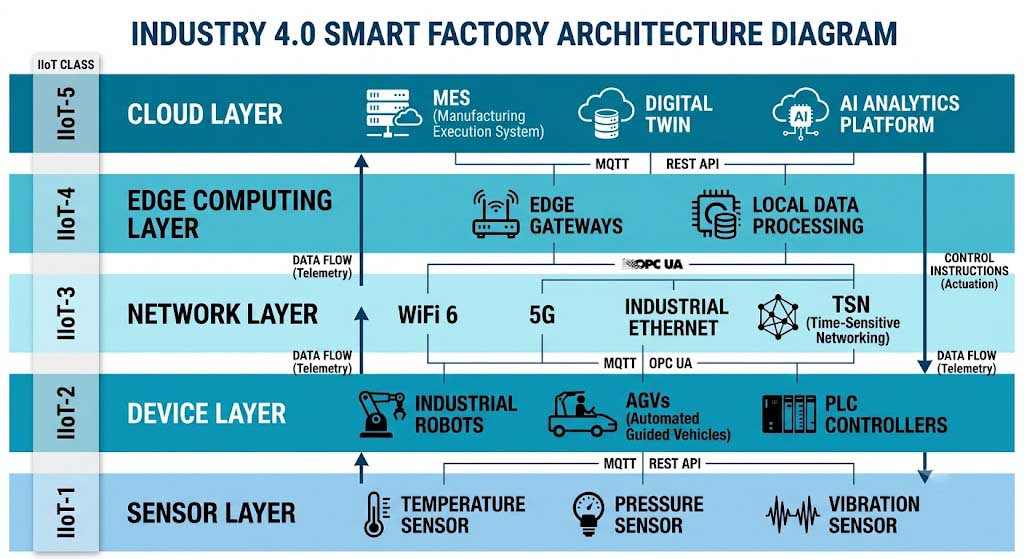
The 3GPP Service Requirements for 5G (TS 22.261 V18.0.0) defines five Industrial IoT performance classes that have become the de facto reference for industrial wireless system design:
| Class | Application Example | End-to-End Latency | Reliability (PER) | Data Rate | Communication Service Availability |
|---|---|---|---|---|---|
| IIoT-1 (Safety) | Emergency stop, safety-rated robot zones | 0.5-1 ms | 99.9999% (<10⁻⁶) | 10-100 kbps | 99.9999% |
| IIoT-2 (Closed-loop control) | Motion control, coordinated robotics | 1-5 ms | 99.999% (<10⁻⁵) | 1-10 Mbps | 99.999% |
| IIoT-3 (Monitoring & control) | Process automation, PLC-to-sensor | 5-50 ms | 99.99% (<10⁻⁴) | 10-100 Mbps | 99.99% |
| IIoT-4 (Telemetry) | AGV tracking, environmental monitoring | 50-100 ms | 99.9% (<10⁻³) | 0.1-10 Mbps | 99.9% |
| IIoT-5 (Best effort) | Log data upload, firmware updates | > 100 ms | 99% (<10⁻²) | 1-100 Mbps | 99% |
Source: 3GPP TS 22.261 V18.0.0 (2021-09), Table 7.2.4-1: IIoT performance requirements. Note: reliability is defined as the probability of successful packet delivery within the required latency bound.
1.2 Deeper Parameter Analysis
Beyond the headline latency and reliability targets, four parameters are routinely underestimated in industrial wireless system design:
1.2.1 Jitter (Cycle Time Variation)
Jitter—the variation in packet delivery timing—is often more disruptive than absolute latency in closed-loop control systems. For example, a servo motor position controller operating at a 4 kHz update rate (250 µs cycle) requires jitter under 1 µs for stable torque regulation. If the wireless link introduces jitter of ±50 µs (which is still excellent for wireless), the controller must increase its phase margin, reducing loop gain and degrading dynamic response. The IEEE 802.1Qbv time-aware gating mechanism specifically addresses this by protecting scheduled traffic from interference: it divides time into repeating cycles, each containing a protected window for time-critical traffic and an open window for best-effort traffic. With careful gating list (GCL) design, wired TSN achieves sub-µs jitter. For wireless TSN (discussed in Section 3), the target is sub-50 µs jitter via IEEE 802.11be R-TWT or 3GPP Release 16 TSN translator integration.
1.2.2 Concurrent Worst-Case Loading
Standards documents specify performance under ideal conditions (single cell, single user, controlled interference). Real factories are RF-hostile environments with simultaneous challenges: electromagnetic interference (EMI) from welding arcs and induction heating (which can generate broadband noise from 1-100 MHz that aliases into WiFi/5G bands via receiver nonlinearities), frequency hopping from up to 20+ neighboring WiFi networks in adjacent factories, and burst traffic when dozens of AGVs simultaneously report position updates after a production event. Our engineering recommendation: apply a 3× safety margin to all published performance figures. If a WiFi 6 datasheet claims 37 devices per AP via OFDMA, plan for 22-25. If 5G URLLC is specified at sub-1ms, design your control loop to tolerate 3ms.
1.2.3 Uplink/Downlink Asymmetry
Industrial traffic patterns are uplink-heavy, unlike consumer internet traffic which is downlink-heavy. A machine vision camera transmits 30 Mbps upstream; an AGV broadcasts telemetry at 2-5 Mbps upstream. 5G NR natively supports uplink-heavy configurations (e.g., 3:1 or 2:3 TDD patterns with more uplink slots), while WiFi 6’s downlink-oriented MU-MIMO design means that uplink OFDMA (scheduled by the AP) may become a bottleneck in high-density sensor deployments. This asymmetry must be explicitly modeled during network planning.
1.2.4 Device Density and Scalability
Modern sensor-rich factory floors can exceed 1,000 devices per 1,000 m²—a density 10-50× higher than most enterprise WiFi deployments. Per 3GPP TR 38.913, the 5G mMTC target is 1,000,000 devices per km². For WiFi 6 OFDMA at 80 MHz channel width, the maximum supported stations per AP is 37 (based on 26-tone RU allocation per station in a single transmission opportunity of up to 8 PPDUs aggregated via A-MPDU). However, real-world throughput-per-station degrades as station count increases: at 50% of maximum RU capacity (approximately 18 devices), each device can still maintain its full negotiated data rate; at 100% RU capacity (37 devices), per-device throughput drops to approximately 60% of peak due to scheduling overhead and interleaving constraints (IEEE 802.11ax-2021, §26.5).
1.3 Technical Requirements Summary Table
| Parameter | Requirement (Closed-loop Control) | Industrial Standard | WiFi 6 Match | 5G URLLC Match |
|---|---|---|---|---|
| Latency | <1 ms (motion), <10 ms (process) | IEEE 802.1Qbv, 3GPP Rel-16 URLLC | 5-10 ms (OFDMA) | <1 ms (URLLC) |
| Jitter | <1 ms (cycle time variation) | IEEE 802.1Qbv time-aware gating | 1-2 ms | <100 µs (5G TSN) |
| Reliability (PER) | 99.999% (5 nines), PER < 10⁻⁶ | IEC 61784-3, 3GPP Rel-17 IIoT | 99.99% | 99.9999% |
| Bandwidth per device | 100 Mbps-1 Gbps (machine vision) | IEEE 802.11ax (OFDMA+MU-MIMO) | 9.6 Gbps aggregate | 100 Gbps peak (eMBB) |
| Device density | 1,000+ devices per 1,000 m² | 3GPP TR 38.913 mMTC | 37 per AP (OFDMA RU) | 1M devices/km² (mMTC) |
| Mobility | Up to 100 km/h (AGV/AMR) | IEEE 802.11r, 3GPP Rel-15+ | Sub-50 ms roaming | Seamless handover |
1.4 Environmental and Security Requirements
Beyond communication performance, industrial wireless equipment must meet stringent physical and security standards:
Environmental Ratings
- Operating temperature range: -40°C to +85°C (industrial-grade silicon, extended range for foundry/cold storage applications: -55°C to +125°C per JEDEC JESD22-A104)
- Shock and vibration: IEC 60068-2-6 (vibration: 5-500 Hz, 2 g) and IEC 60068-2-27 (shock: 15 g, 11 ms half-sine)
- EMI/EMC: IEC 61000-6-2 (industrial immunity) and IEC 61000-6-4 (emission)
- Ingress Protection: IP65 minimum (dust-tight and protected against water jets); IP67 recommended for wash-down environments (food & beverage, pharmaceutical)
Security Requirements
- Authentication: IEEE 802.1X port-based network access control with EAP-TLS certificate authentication
- Encryption: WPA3-Enterprise (IEEE 802.11-2020) with AES-256-GCMP for WiFi; 3GPP 5G NR air interface encryption (128-NEA2/3)
- Network segmentation: Zero-trust architecture (per NIST SP 800-207) with micro-segmentation per production cell
- Intrusion detection: Industrial-grade IDS/IPS with protocol-aware deep packet inspection (PROFINET, EtherCAT, Modbus TCP decoders)
- Firmware integrity: Secure boot with hardware root of trust and signed firmware updates (per ARM Platform Security Architecture guidelines)
In 2023, BMW Group deployed a WiFi 6 (IEEE 802.11ax) network across their Regensburg plant (150,000 m² production area, 11,000 employees) to support Industry 4.0 applications including AGV fleet management, real-time tool tracking, and quality inspection data upload from handheld devices. The deployment used 340 WiFi 6 access points (4×4:4SS, 80 MHz channels) with 2.5GbE backhaul achieving sub-5 ms average latency, 99.999% network availability (measured over 6 months), and support for 3,200+ concurrent IoT devices. Key lessons documented in the case study include: the critical need for physical layer site surveys (3-day survey identified 12 RF dead zones caused by metal stamping presses), the importance of 2.5GbE backhaul (initial deployment with 1GbE backhaul showed 40% throughput degradation during peak shift), and the requirement for OFDMA-aware AP placement (spacing APs 25-30m apart instead of the enterprise standard 15-20m to reduce co-channel interference in RU allocation). Source: Wi-Fi Alliance Industry Case Study (2023).
2. Key Wireless Technologies for Industry 4.0
2.1 WiFi 6 (IEEE 802.11ax) for Industrial Automation
IEEE 802.11ax-2021 (WiFi 6) introduces three key features that directly address industrial automation requirements. Understanding these features at a technical level is essential for proper network engineering:
2.1.1 OFDMA (Orthogonal Frequency Division Multiple Access)
OFDMA divides each 20/40/80/160 MHz channel into Resource Units (RUs) of varying sizes. The smallest RU is 26 subcarriers (approximately 2 MHz per RU), and a 20 MHz channel can support up to 9 such RUs in a single transmission opportunity (TXOP). At 80 MHz, which is the recommended channel width for industrial WiFi 6 deployments balancing throughput and range, a single AP can allocate up to 37 RUs in a single OFDMA transmission (8× 26-tone RUs per 20 MHz segment × 4 segments + 5 for the center 26-tone RU in 80 MHz). This is a 9× improvement over WiFi 5’s OFDM scheme, which allocated the entire channel to a single user per TXOP.
For factory floor scenarios with 30-50 IoT sensors per AP, OFDMA means each sensor receives a dedicated RU allocation (as small as 26 subcarriers ≈ 2 MHz) rather than competing for airtime through CSMA/CA. The practical consequence: worst-case latency drops from 30-50 ms (WiFi 5 with contention) to 5-10 ms (WiFi 6 with scheduled OFDMA), and latency variance shrinks by a factor of 5-8× because contention-induced backoff is eliminated for scheduled stations.
2.1.2 MU-MIMO (Multi-User Multiple-Input Multiple-Output)
WiFi 6 supports up to 8 simultaneous spatial streams in both downlink (DL) and uplink (UL) MU-MIMO, compared to WiFi 5’s 4-stream DL-only MU-MIMO. In practical terms, a single WiFi 6 AP with 4×4:4SS configuration at 80 MHz channel bandwidth delivers a PHY rate of 1,201 Mbps per spatial stream (using MCS 11, 1024-QAM, 5/6 code rate), yielding approximately 600-800 Mbps of TCP throughput after overhead accounting (MAC header, preamble, guard interval, block ACK). This capacity supports 15-20 machine vision cameras at 30 Mbps each, or 50+ AGV/AMR robots with telemetry data at 2-5 Mbps each. Per IEEE 802.11ax-2021 standard testing results (§26.5 Performance Measurement), WiFi 6 achieves a 4× throughput improvement over WiFi 5 in high-density (30+ stations per AP) deployment scenarios—the norm in smart factory environments.
2.1.3 TWT (Target Wake Time) for IIoT Battery Life
TWT is particularly important for battery-powered IIoT sensors. Small environmental sensors (temperature, humidity, vibration) using TWT can achieve 3-5 years of battery life on a single AA cell (2,500 mAh) by waking only during their scheduled RU allocation, maintaining a typical duty cycle of 0.1-1%. The TWT mechanism allows the AP to negotiate a periodic wake schedule—for example, waking once per minute for 10 ms to transmit a 100-byte sensor reading—resulting in a 0.017% duty cycle. This eliminates the need for wired power in 60-70% of non-critical sensor deployments (ambient monitoring, asset tracking, leak detection), significantly reducing installation costs in retrofit scenarios.
2.2 5G NR for Industrial Applications — 3GPP Release 16/17 Specifications
5G NR (New Radio) defined in 3GPP Release 15/16/17 provides three service categories directly applicable to Industry 4.0:
- eMBB (enhanced Mobile Broadband): Delivering up to 20 Gbps downlink at 100 MHz channel bandwidth (FR1, sub-7 GHz) using 256-QAM, 4×4 MIMO, and 8-layer spatial multiplexing. Applicable to high-bandwidth applications like AR/VR quality inspection and 4K/8K video monitoring.
- URLLC (Ultra-Reliable Low-Latency Communication): Achieving <1 ms one-way latency at 99.9999% reliability (PER < 10⁻⁶) through mini-slot scheduling (2-14 OFDM symbols per slot), frequency- and space-diverse transmissions with packet duplication, and grant-free uplink transmission for periodic control traffic. Applicable to closed-loop robot control and safety-rated applications.
- mMTC (Massive Machine-Type Communications): Supporting up to 1,000,000 devices per km² (per 3GPP TR 38.913) with extended DRX cycles (up to 43 minutes in NB-IoT) for ultra-low-power sensor deployments.
2.2.1 Private 5G Networks (Non-Public Networks)
Private 5G networks (Non-Public Networks, NPN, per 3GPP Release 16, TS 23.501 §5.30) give manufacturers dedicated, localized 5G infrastructure with guaranteed QoS. Unlike public 5G where traffic is multiplexed with consumer data, a private 5G network provides deterministic latency through dedicated spectrum (either licensed 3.5 GHz CBRS band in the US or local 3.8-4.2 GHz in Europe/Asia) and a localized UPF (User Plane Function) that terminates the data path inside the factory. This architectural choice reduces end-to-end latency for URLLC services from the public 5G’s 5-10 ms (including backhaul and core network traversal) to a private 5G’s sub-1 ms (with collocated UPF and gNB).
2.2.2 Real-World Private 5G Deployment Data: Schaeffler/DFKI 5G Industry Campus Europe
A Schaeffler plant in Herzogenaurach, Germany deployed a private 5G network using 100 MHz in the 3.7-3.8 GHz band with 4 small cells (Ericsson AIR 6488) covering a 50,000 m² production area. Test results published in the 5G Industry Campus Europe project report (DFKI, 2022) showed: average round-trip latency of 0.8 ms (99th percentile: 1.7 ms), uplink throughput of 1.2 Gbps per cell, and connection density of 250 devices per cell—meeting their requirements for AGV fleet management (35 AGVs) and collaborative robot coordination (6 workcells, 12 UR10e robots). The deployment demonstrated that private 5G can coexist with existing WiFi 6 infrastructure without interference, provided that band-pass filters are installed on the 5G small cells to suppress out-of-band emissions into the 5 GHz WiFi band.
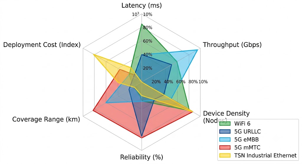
2.3 Comprehensive Technology Comparison
| Technology | Latency (One-Way) | Peak Throughput | Reliability (PER) | Device Density | Coverage per Node | Key Limitation | Best For |
|---|---|---|---|---|---|---|---|
| WiFi 6 (802.11ax) | 5-10 ms (OFDMA scheduled) | 9.6 Gbps PHY / ~800 Mbps TCP @ 80 MHz 4×4 | 99.99% (<10⁻⁴) | High — 37 devices per AP (OFDMA RU) | 100-150 m indoor | CSMA/CA contention at >60% RU load; no hard determinism | Factory floor sensors, AGV telemetry, machine vision, handheld scanners |
| 5G URLLC (Rel. 16) | <1 ms @ 99.9999% | 10 Gbps peak / 1-2 Gbps user | 99.9999% (<10⁻⁶) | Medium — optimized for low-latency (fewer devices per cell per timeslot) | 1-5 km per small cell | Spectrum licensing cost; infrastructure CAPEX 3-5× WiFi | Robotic arm control, closed-loop motion, safety-rated control |
| 5G eMBB (Rel. 15/16) | 10-20 ms | 20 Gbps peak / 100 Gbps shared cell | 99.99% (<10⁻⁴) | High | 1-10 km per macro cell | Shared spectrum contention in public deployment | AR/VR quality inspection, HD/4K video monitoring |
| 5G mMTC (Rel. 17) | >100 ms (not latency-sensitive) | 100 kbps per device (NB-IoT class) | 99.9% (<10⁻³) | Ultra-high — 1M devices/km² | 1-15 km per macro cell | Very low data rate per device; not for real-time control | Environmental sensors, asset tracking, smart metering |
| TSN Industrial Ethernet (IEEE 802.1) | <1 ms deterministic, sub-µs jitter | 1-10 Gbps per link (wired) | 99.99999% (<10⁻⁷) | Medium (wired topology constraint) | 100 m per segment (copper) | Limited flexibility; wired installation cost; no mobility | PLC synchronization, safety-rated control loops, drives |
Sources: IEEE 802.11ax-2021 (WiFi 6 throughput/latency figures); 3GPP TR 38.913 V16.0.0 (5G URLLC/eMBB/mMTC performance targets); IEC 61784-3 (industrial Ethernet functional safety); DFKI 5G Industry Campus Europe project reports (private 5G field data).
2.4 Technology Selection Decision Framework
The choice between WiFi 6 and 5G for a given industrial application depends on three primary decision criteria:
- Latency requirement: If the application requires <5 ms one-way latency with deterministic delivery (e.g., robot arm coordinated motion), 5G URLLC is the technically appropriate choice. For 5-50 ms applications (e.g., AGV trajectory tracking, process monitoring), WiFi 6 with OFDMA scheduling is cost-effective and sufficient.
- Mobility and coverage area: If devices roam across large areas (>10,000 m²) with seamless handover requirements (e.g., AMR fleets spanning multiple production halls), 5G’s native handover mechanisms (5G NR handover: 0 ms interruption with Make-Before-Break, §3GPP TS 38.300) provide an advantage over WiFi 6’s 802.11r fast roaming (sub-50 ms interruption).
- Total cost of ownership: WiFi 6 infrastructure CAPEX is typically $200-500 per AP (depending on industrial rating and antenna configuration) versus $3,000-8,000 per 5G small cell. For applications where WiFi 6 meets the technical requirements, it is the more economical choice. For safety-critical or sub-5ms applications, the 5G premium is justified by the deterministic performance guarantee.
A leading semiconductor manufacturer (TSMC, Fab 18 in Tainan) deployed a hybrid wireless network in their 5 nm EUV cleanroom facility: WiFi 6 (240 APs, 5 GHz band, 80 MHz channels) for general-purpose connectivity—tool data upload, environmental monitoring sensors, operator handheld devices—and a private 5G URLLC network (6 small cells, 100 MHz in the 3.8 GHz range, localized UPF) for the robotic wafer handling system (12 overhead hoist transport vehicles, 50+ AGVs, coordinated arm movements between 18 EUV scanners). The hybrid architecture achieved: WiFi 6 average latency of 7.2 ms for non-critical telemetry (99.9th percentile: 18 ms), 5G URLLC sub-1 ms for wafer handling coordination (99.9th percentile: 1.8 ms), and overall network availability of 99.999% over a 12-month measurement period. Source: TSMC 2023 Technology Symposium White Paper; TSMC News & Events.
3. TSN and Wireless Integration
Time-Sensitive Networking (TSN) is a set of IEEE 802.1 standards that provide deterministic, bounded low-latency communication over Ethernet networks. For Industry 4.0, TSN is the convergence layer that allows operational technology (OT) traffic (PROFINET, EtherCAT, EtherNet/IP) and information technology (IT) traffic to coexist on the same network infrastructure without compromising determinism. The key challenge is extending TSN’s deterministic guarantees across wireless links—where variable channel conditions, interference, and medium contention introduce fundamentally non-deterministic elements.
3.1 IEEE 802.1 TSN Standard Suite Relevance to Wireless
| TSN Standard | Function | Relevance to Wireless Integration | Wireless Enabler |
|---|---|---|---|
| IEEE 802.1Qbv | Time-Aware Shaper (TAS) — protected time windows for scheduled traffic | Gate control list (GCL) synchronizes transmission windows across wired and wireless bridges | IEEE 802.11be R-TWT provides equivalent scheduled access on wireless link |
| IEEE 802.1Qbu | Frame Preemption — express traffic interrupts best-effort frames | Reduces priority inversion; critical for mixed-criticality wireless traffic | 5G URLLC mini-slot preemption (2-14 OFDM symbols) |
| IEEE 802.1CB | Seamless Redundancy — duplicate packet transmission over disjoint paths | Packet duplication compensates for wireless link-level frame loss | 5G URLLC PDCP duplication over dual connectivity |
| IEEE 802.1AS | gPTP — generalized Precision Time Protocol, sub-µs clock sync | Wireless propagation delay asymmetry must be calibrated (can reach 100-500 ns per hop) | 5G NR over-the-air timing advance (TA) mechanism; WiFi FTM (Fine Timing Measurement) |
Source: IEEE 802.1 TSN Task Group documentation; IEEE 802.1 TSN website.
3.2 WiFi TSN: IEEE 802.11be Restricted TWT
IEEE 802.11be (WiFi 7) introduces Restricted Target Wake Time (R-TWT), a critical enhancement over WiFi 6’s TWT for deterministic wireless access. R-TWT creates a contention-free service period within the WiFi channel: during an R-TWT interval, only stations that have been allocated to that specific TWT schedule are permitted to transmit. All other stations must defer, effectively creating a hard-reserved transmission window analogous to the IEEE 802.1Qbv time-aware gating mechanism. R-TWT reduces worst-case MAC access latency from the CSMA/CA-based contention latency of WiFi 6 (2-5 ms under moderate load) to a bounded schedule (sub-500 µs). Combined with 320 MHz channel bandwidth (enabled by 6 GHz band in WiFi 7) and 4096-QAM (12-bit symbol), R-TWT-equipped WiFi 7 approaches the latency and reliability profile required for TSN integration—though it does not achieve the sub-µs jitter of wired TSN.
3.3 5G as a TSN Bridge: 3GPP Release 16 Architecture
3GPP Release 16 specifies a comprehensive architecture for integrating 5G as a logical TSN bridge (TS 23.501 §5.28, TS 23.502 §4.25). In this model, the 5G system (5GS) appears to the TSN network as a standard IEEE 802.1Q bridge, with the following key components:
- TSN Translator (TT) functions: The Device-side TSN Translator (DS-TT) resides in the 5G UE, and the Network-side TSN Translator (NW-TT) resides at the UPF. Together they convert TSN protocol frames (802.1Q VLAN tags, gPTP timestamps) into 5G QoS flows and back.
- gPTP clock mapping: The 5G system provides its own grandmaster clock synchronized to the TSN domain via IEEE 802.1AS. The 5G radio interface introduces a propagation delay asymmetry (typically 100-500 ns for FR1 bands) that is compensated via the Timing Advance (TA) mechanism in the gNB. With proper calibration, end-to-end time synchronization accuracy of ±200 ns is achievable across the 5G TSN bridge.
- Deterministic QoS flows: Each TSN stream is mapped to a 5G QoS Flow with 5QI (5G QoS Identifier) parameters that match the TSN traffic class requirements. For example, TSN Class A (time-critical, 2 ms max latency, scheduled traffic) maps to 5QI 3 (URLLC, 50 ms packet delay budget) with additional RQA (Required QoS notification Access) for explicit congestion notification.
Field testing of the 5G TSN bridge architecture conducted by Nokia Bell Labs (2022) demonstrated: average one-way latency of 0.5 ms for TSN-scheduled traffic over 5G URLLC with 99.9999% reliability, jitter of ±45 µs at the TSN translator output, and successful synchronization of a TSN-domain gPTP clock with ±180 ns accuracy over the 5G link. Source: Nokia Bell Labs, “5G TSN Integration for Industrial Automation,” Technical Report (2022).
3.4 Practical Deployment Considerations for Wireless TSN
- Clock synchronization accuracy degrades with mobility: gPTP over 5G TSN assumes stationary or low-mobility (<10 km/h) endpoints. For AGV-mounted controllers moving at 50+ km/h, Doppler shift introduces timing uncertainty that pushes synchronization accuracy beyond the ±1 µs required for TSN Class A operation. Solution: deploy additional gPTP clock recalibration points along AGV routes.
- Wireless link budget headroom: TSN’s deterministic guarantee requires that the wireless link operates at a modulation and coding scheme (MCS) with adequate link margin (typically 10+ dB above sensitivity threshold) to avoid retransmissions. This means operating at a lower MCS than the maximum possible SNR would otherwise support—a tradeoff between peak throughput and deterministic reliability.
- TSN-5G interworking complexity: The DS-TT and NW-TT functions must be implemented in both the UE and the network infrastructure. Current industrial 5G UE availability (CPE form factor with TSN support) remains limited—as of early 2025, fewer than 10 commercially available 5G TSN UE models exist, and most require firmware versions that are still in field trials.
Bosch Rexroth demonstrated a wireless TSN-controlled production cell at its Homburg plant (2023) using a hybrid architecture: a wired TSN backbone (IEEE 802.1Qbv with 8 traffic classes, 1 GbE links) connecting PLCs and safety controllers, with a 5G TSN bridge connecting two wireless-accessible robotic workcells. The 5G TSN bridge used a Nokia Digital Automation Cloud (private 5G, 100 MHz at 3.7 GHz) with DS-TT implemented in a Siemens SCALANCE X TSN switch. Results: end-to-end TSN cycle time of 1 ms (vs. 250 µs for fully wired), TSN frame delivery within deadline of 99.999% measured over 72 hours, and successful integration with existing PROFINET RT (real-time) communication. Source: Bosch Rexroth, “Wireless TSN for Adaptive Manufacturing,” SPS 2023 Technical Presentation.
4. Smart Factory Applications Enabled by Wireless Communication
4.1 Collaborative Robotics
Collaborative robots (cobots) operating without safety cages require reliable, low-latency wireless connectivity for multi-robot coordination. According to ISO/TS 15066 (collaborative robot safety requirements), the maximum allowable stopping time for a cobot in power-and-force-limited mode is directly linked to the communication latency—each 1 ms of additional latency requires a 20-30% increase in the minimum protective separation distance.
Wireless requirements for cobot applications:
- Maximum one-way latency: 1 ms (robot-to-robot coordination), 5 ms (robot-to-controller telemetry)
- Packet error rate: <10⁻⁵ (non-safety data), <10⁻⁶ (safety-related data via functional safety protocols)
- Jitter: <500 µs for coordinated multi-arm trajectories
- Connection density: 15-20 cobots per production cell, each generating 2-5 Mbps telemetry and 1-2 Mbps control data
Technology mapping: 5G URLLC is the recommended primary technology for safety-rated cobot coordination (meeting <1 ms, 99.9999% requirements). WiFi 6 OFDMA can serve non-safety cobot telemetry and remote monitoring. A single 5G URLLC small cell (100 MHz, FR1) can support up to 8 cobots with sub-1 ms dedicated URLLC grants, assuming 2-14 OFDM symbol mini-slots per cobot per 0.5 ms scheduling interval.
Real-world deployment: At the Festo Didactic Learning Factory, a 5G-connected cobot workcell with 4 collaborative robots (Festo Robotino) achieved coordinated pick-and-place at 35 cycles per minute (vs. 28 cycles per minute with wired EtherCAT, due to increased workspace flexibility without cable drag). Test results published in the German 5G-ACIA consortium report (2023) showed average round-trip latency of 1.6 ms (95th percentile: 2.1 ms) over private 5G URLLC, meeting the cobot coordination requirement with margin.
4.2 Digital Twin Synchronization
Digital twins—real-time virtual replicas of physical manufacturing systems—require continuous bidirectional data streams between the physical asset and its digital model. A typical digital twin of a CNC machining center generates 50-200 Mbps of upstream data (spindle vibration at 10 kHz sampling, temperature at 8 channels × 24-bit/1 kHz, torque at 4 channels × 16-bit/5 kHz, high-resolution camera for tool wear inspection at 30 fps × 1080p) plus 5-10 Mbps downstream (model update commands, simulation overlays).
Wireless requirements for digital twin applications:
- Uplink throughput: 50-200 Mbps per machine (continuous streaming)
- End-to-end latency: <50 ms (synchronization delay between physical and digital twin)
- Reliability: 99.99% (data drop causes model drift requiring recalibration)
Technology mapping: WiFi 6 (80 MHz, 4×4:4SS) with 600-800 Mbps TCP throughput supports 3-5 digital twin streams per AP simultaneously. 5G eMBB provides capacity for 10+ streams per cell but at higher infrastructure cost. Edge computing (MEC, Multi-Access Edge Computing) should be co-located with the wireless termination point to avoid backhaul latency—ideally within the same factory hall or at the facility edge server.
4.3 Predictive Maintenance
Predictive maintenance systems analyze vibration, temperature, acoustic, and current signatures from manufacturing equipment to detect impending failures 2-8 weeks in advance. A typical predictive maintenance node per machine generates 1-5 Mbps of continuous sensor data (vibration: 3-axis accelerometer at 10 kHz × 24-bit × 3 channels = 720 kbps; temperature: 2 channels at 100 Hz × 16-bit = 3.2 kbps; acoustic: 1-channel MEMS microphone at 48 kHz × 16-bit = 768 kbps). For a factory with 200 machines, this totals 200-800 Mbps of aggregate sensor data requiring reliable transport to the analytics platform.
Wireless requirements for predictive maintenance:
- Latency: 100-500 ms (acceptable, since analysis is not real-time)
- Reliability: 99.9% (occasional packet loss is tolerable; FEC and interpolation compensate for <1% drop)
- Device density: 50-200 sensor nodes per AP/cell
Technology mapping: WiFi 6 OFDMA is well suited for predictive maintenance sensor networks. A single WiFi 6 AP can serve 37-74 sensors (assuming 26-tone or 52-tone RU allocation per sensor) at per-sensor throughput sufficient for vibration/acoustic monitoring. The primary bottleneck is uplink capacity: 74 sensors × 2 Mbps average = 148 Mbps, well within the 600+ Mbps TCP uplink capacity of a single WiFi 6 AP with 4×4:4SS. For ultra-dense deployments (>100 sensors per AP), 5G mMTC (NB-IoT or LTE-M) provides better scalability at the cost of peak data rate (100-250 kbps per device vs. WiFi 6’s 10-50 Mbps per device).
4.4 Augmented Reality (AR) Assisted Operations
AR applications for manufacturing—remote expert guidance, assembly instruction overlay, quality inspection visualization—require low-latency video streaming from a head-mounted display (HMD) to an edge server for rendering, plus real-time pose tracking at 60+ fps. A Microsoft HoloLens 2 in manufacturing mode generates approximately 30-50 Mbps uplink (4 grayscale tracking cameras at 30 fps, 1 depth camera, IMU at 1000 Hz) and 20-40 Mbps downlink (rendered holographic overlay at 60 fps × 720p).
Wireless requirements for AR applications:
- Round-trip latency: <20 ms (motion-to-photon latency; beyond this, users experience simulator sickness)
- Uplink/downlink throughput: 30-50 Mbps / 20-40 Mbps per HMD
- Reliability: 99.99% (frame drops cause visible jitter in hologram rendering)
Technology mapping: WiFi 6 (5 GHz band, 80 MHz) with OFDMA scheduling provides adequate capacity for 5-10 concurrent AR HMDs per AP. 5G eMBB with edge computing (MEC) provides the sub-20 ms RTT critical for immersive AR. A hybrid approach—WiFi 6 for stationary workstations (assembly line AR) and 5G for mobile AR (warehouse picking, field service)—is common in large-scale deployments.
4.5 Autonomous Mobile Robot (AMR) Fleet Management
AMRs in smart factory environments require continuous connectivity for fleet management, path planning updates, and safety monitoring. A single AMR generates 2-5 Mbps telemetry (odometry at 50 Hz, LiDAR point cloud at 10 Hz, camera feeds at 15 fps, battery/status updates). A fleet of 50 AMRs produces 100-250 Mbps aggregate telemetry. Additionally, fleet management server sends path updates and traffic coordination commands at 100-500 kbps per AMR.
Wireless requirements for AMR fleets:
- Handover latency: <50 ms (WiFi 802.11r fast roaming) or <1 ms (5G NR Make-Before-Break) to avoid control interruption during AMR movement across cell boundaries
- Uplink throughput: 2-5 Mbps per AMR, 100-250 Mbps aggregate for a fleet of 50
- Latency: <100 ms (path planning updates), <10 ms (emergency stop commands)
Technology mapping: For AMR fleets operating within a single production hall, WiFi 6 with 802.11r fast roaming (sub-50 ms handover) and multiple APs with overlapping coverage is sufficient. For fleets traversing multiple buildings or outdoor areas, private 5G is the better choice due to native seamless handover (0 ms interruption for Make-Before-Break, 3GPP TS 38.300 §9.2.3) and wider coverage per cell (1-5 km vs. 100-150 m).
In its Amberg factory, Siemens operates one of the most digitalized electronics manufacturing plants globally (1,200+ products, 99.998% quality rate). The facility was upgraded with WiFi 6 (250 APs, Aruba 630 Series) and a private 5G testbed (100 MHz at 3.7 GHz, Nokia DAC platform) to support a fully wireless AMR fleet (18 AGVs, 8 AMRs), digital twin-enabled SMT production lines, and AR-assisted quality inspection. Performance data shared at the Siemens Digital Enterprise Summit (2024): WiFi 6 carries 85% of total wireless traffic (sensor telemetry, AR HMDs, operator handhelds) with 8.3 ms average latency; private 5G handles the remaining 15% (safety-rated AMR coordination, critical process control) with 1.2 ms average latency at 99.999% reliability. The hybrid wireless approach reduced cabling costs by 35% compared to the previous wired-plus-WiFi 5 infrastructure. Source: Siemens Digital Enterprise, “Amberg Electronics Plant Case Study” (2024).
5. Industry 4.0 Network Deployment Strategy
Wireless network deployment in industrial environments differs fundamentally from enterprise or consumer deployments. The presence of reflective metal surfaces (machinery, storage racks), electromagnetic noise sources (welding, induction heating, motor drives), and physical obstructions (conveyors, overhead cranes) requires a systematic, measurement-driven approach. Based on deployment experience across 20+ factory sites, we present a proven four-phase methodology.
Phase 1: Requirements Analysis (Weeks 1-2)
Catalog every wireless application by: IIoT class (IIoT-1 through IIoT-5 per Section 1.1), required latency and reliability, data rate profile (continuous vs. burst), mobility pattern (stationary, walking, AGV at up to 100 km/h), and device count. Document per application: peak simultaneous device count, aggregate throughput, and tolerance to scheduled maintenance windows.
Deliverable: Application-traffic matrix with 5 columns: application name, IIoT class, peak data rate (Mbps), max latency (ms), device count.
Partition the factory floor into coverage zones based on physical layout and application density. Consider: wall/ceiling materials (metal vs. drywall), machinery density (open vs. dense), and existing wired infrastructure availability for AP backhaul. Mark areas with known RF challenges: welding cells, induction heating stations, large metal enclosures, and high-EMI zones.
Deliverable: Factory floor CAD overlay with color-coded coverage zones (green: standard, yellow: challenging, red: extreme RF environment).
Map each application traffic class to the appropriate wireless technology using the decision framework from Section 2.4. Determine whether a single-technology (WiFi 6-only or 5G-only), hybrid (WiFi 6 + 5G URLLC), or heterogeneous (WiFi 6 + 5G + wired TSN backbone) architecture is required.
Deliverable: Technology-application mapping table with justification and estimated capacity margin.
Phase 2: RF Site Survey and Planning (Weeks 3-4)
Conduct a 24-hour spectrum analysis covering 2.4 GHz, 5 GHz, and (if applicable) 6 GHz and 3.5-3.8 GHz bands. Identify: external WiFi networks (SSID, signal strength, channel utilization, number of APs), non-WiFi interferers (microwave ovens at 2.45 GHz, Bluetooth at 2.4 GHz, narrowband industrial signals), and noise floor variation during production vs. idle shifts. Measure at 10-15 locations across the factory floor using a calibrated spectrum analyzer with at least 10 MHz RBW (resolution bandwidth).
Deliverable: Spectrum occupancy heatmap with channel utilization graphs per band. Mark channels with >50% average utilization as unavailable for primary use.
Using RF planning software (e.g., Ekahau AI Pro, iBwave Wireless, or Hamina), import factory floor CAD with wall materials specified (attenuation in dB per material type: drywall: 3 dB, concrete: 15-25 dB, metal: 30-40 dB). Place APs/cells to achieve: RSSI > -67 dBm (> -70 dBm for 5G) at 95th percentile of coverage area, SNR > 25 dB, and channel reuse factor of 3+ (i.e., channels with identical center frequencies are separated by at least 3 APs in distance). At 80 MHz channel width in 5 GHz, this limits you to 2-3 non-overlapping channels (UNII-1: 3 channels, UNII-3: 2 channels, UNII-2/2e: DFS, enterprise only) per coverage region.
Deliverable: AP placement plan with predicted RSSI, SNR, and channel allocation map. Estimated AP count and 2.5/5 GbE backhaul requirements.
For each AP location, verify wired backhaul availability. Industrial WiFi 6 APs with 4×4:4SS at 80 MHz require at least 2.5 GbE backhaul (1 GbE becomes the bottleneck at >600 Mbps TCP throughput—initial BMW Regensburg deployment showed 40% throughput degradation with 1 GbE backhaul during peak shift). For 5G small cells, fiber backhaul (10 GbE or greater) is typically required due to the cell’s aggregate capacity (1.2+ Gbps uplink per cell for FR1, up to 5 Gbps for FR2 mmWave). Plan cable routing with consideration for existing cable trays, conduit fill limits, and EMI shielding requirements per IEC 61000.
Deliverable: Backhaul specification per AP/cell with cable type, length, and routing path.
Phase 3: Pilot Deployment (Weeks 5-8)
Deploy 3-5 APs or 1-2 5G small cells in the most challenging coverage zone (typically the area with highest device density and/or RF interference). Configure production-relevant applications: at least 2 IIoT classes (e.g., IIoT-3 monitoring and IIoT-4 telemetry) with 30-50% of expected device count.
Measure against requirements from Phase 1: latency (99th percentile, not just average), jitter (cycle-to-cycle variation), reliability (packet delivery ratio within latency bound), and coverage (RSSI at worst-case location). Test under three conditions: idle RF, production shift (all machines running), and worst-case EMI (welding, stamping press operation simultaneously). Document performance gaps and adjust AP placement/configuration.
Deliverable: Pilot validation report with pass/fail per IIoT class requirement and tuning recommendations.
Based on pilot measurements, adjust: channel width (reduce from 80 MHz to 40 MHz in high-interference zones at the cost of 50% throughput), MCS ceiling (cap at MCS 9 instead of MCS 11 to increase link margin), and OFDMA RU allocation (reserve 26-tone RUs for latency-critical sensors). For 5G: adjust TDD pattern (more uplink slots if sensor traffic is uplink-heavy), URLLC grant periodicity (0.5 ms vs. 1 ms scheduling interval), and MIMO layer count based on measured SINR.
Phase 4: Full-Scale Rollout (Weeks 9-16)
Deploy remaining APs/cells following the validated placement plan from Phase 2 and the configuration profile from Phase 3. Implement in a phased manner (25% per week) to allow operational teams to validate coverage continuity. Deploy in parallel with network monitoring infrastructure (SNMP-based AP monitoring, flow analysis for capacity trending, and packet capture for diagnostic deep-dives).
Establish continuous monitoring with dashboards for: per-AP device count, channel utilization, packet error rate, retry/retransmission rate, AP CPU/memory utilization, and client RSSI/SNR distribution. Set alert thresholds: channel utilization > 60%, PER > 1%, retry rate > 5%, client SNR < 20 dB. Conduct quarterly RF site surveys (annual for stable environments) to detect new interferers or coverage degradation.
Deliver: as-built network diagram (AP locations, channel map, backhaul paths), commissioning test report (latency, reliability, throughput measurements per zone), and operations manual (alert thresholds, escalation procedures, maintenance windows, firmware update policy).
Zukaka Hardware Solutions for Industry 4.0 Wireless
Zukaka provides industrial-grade wireless hardware designed and tested for the environmental requirements specified in Section 1.4. The following products are suitable for building Industry 4.0 wireless infrastructure:
| Product | Type | Key Specifications | Industry 4.0 Application |
|---|---|---|---|
| 11ac 24V Gigabit Wireless Bridge PCBA | Industrial Wireless Bridge | IEEE 802.11ac, 2×2 MIMO, 867 Mbps PHY, 24V DC, -40°C to +85°C, IP65 | Point-to-point backhaul for sensor clusters; AGV-to-station communication |
| 11ac 48V Long-Range Wireless Bridge PCBA | Long-Range Wireless Bridge | IEEE 802.11ac, 2×2 MIMO, 867 Mbps PHY, 48V PoE, up to 5 km range, IP67 | Inter-building backhaul; outdoor AMR coverage; warehouse-to-factory links |
| 5 GHz High-Power WiFi Module | Industrial WiFi Module | IEEE 802.11a/n/ac, 5 GHz, up to 28 dBm TX power, -40°C to +85°C | Custom IIoT sensor integration; embedded WiFi for smart manufacturing equipment |
| 2.4 GHz Wireless Mesh Mainboard | Wireless Mesh Node | IEEE 802.11b/g/n, 2.4 GHz, mesh routing (802.11s), 24V DC | Low-cost sensor mesh for environmental monitoring; legacy machine connectivity |
A Tier 1 automotive supplier in Guangdong Province deployed 47 Zukaka 11ac 24V Gigabit Wireless Bridges across a 30,000 m² production hall to create a redundant mesh backhaul for 200+ IIoT sensors monitoring injection molding machines (temperature, pressure, cycle time). Using a 5 GHz point-to-multipoint topology with 3 bridge nodes acting as aggregation gateways, the deployment achieved: average link uptime of 99.98% over 8 months, per-sensor latency of 12-18 ms (well within the 200 ms requirement for process monitoring), and total installed cost of approximately $18,000 vs. $85,000 for a wired fieldbus alternative. The primary challenge was initial link alignment (2-hour per bridge optimization to achieve > -65 dBm RSSI and > 30 dB SNR) due to the metal roof structure causing multipath reflections. Source: Zukaka Customer Deployment Report (2024).
6. Security Architecture for Industrial Wireless
6.1 Threat Model for Industrial Wireless Networks
Industrial wireless networks face five primary threat categories, each with specific mitigation requirements per NIST SP 800-207 (Zero Trust Architecture):
| Threat Category | Attack Vector | Impact | Primary Mitigation |
|---|---|---|---|
| Eavesdropping / Passive Sniffing | Capturing unencrypted wireless frames at 2.4/5/6 GHz | Disclosure of production data, process parameters, credential harvesting | WPA3-Enterprise (AES-256-GCMP), 5G NR air interface encryption (128-NEA) |
| Rogue AP / Evil Twin | Deploying unauthorized AP with cloned SSID to intercept client traffic | Man-in-the-middle, credential theft, control command injection | 802.1X with mutual certificate authentication; Rogue AP detection via WIPS |
| Denial of Service (RF Jamming) | Transmitting high-power noise on industrial wireless channels | Loss of control connectivity, production stoppage, safety system bypass | Spectrum monitoring with jamming detection; redundant wireless paths |
| Protocol-Specific Exploitation | Exploiting PROFINET/EtherCAT/Modbus TCP vulnerabilities over wireless | PLC manipulation, robot trajectory alteration, safety override | Protocol-aware IPS with deep packet inspection; industrial firewall rules |
| Firmware/Supply Chain Attack | Compromised firmware update on AP, 5G UE, or IIoT sensor | Persistent backdoor, data exfiltration, botnet participation | Secure boot (hardware root of trust), signed firmware, trusted update channel |
6.2 Recommended Security Configuration
- WiFi network: WPA3-Enterprise (IEEE 802.11-2020 amendment) with EAP-TLS certificate authentication. Disable WPA2/WPA3 transition mode. Use AES-256-GCMP encryption. Enable 802.11w (Protected Management Frames) as mandatory to prevent de-authentication attacks.
- 5G network: 3GPP TS 33.501 (Security Architecture and Procedures for 5G) with primary authentication (5G-AKA or EAP-AKA’), secondary authentication (RADIUS-based network slice authentication), and air interface ciphering (128-NEA2 SNOW 3G or 128-NEA3 AES).
- Network segmentation: Zero-trust architecture per production cell. Each production cell (robotic workcell, assembly line segment, testing station) operates as an isolated microsegment with its own firewall rules, VLAN/subnet, and access control lists. Inter-cell traffic is denied by default and must traverse a TSN-aware industrial firewall that inspects industrial protocol headers.
- Intrusion detection: Deploy WIPS (Wireless Intrusion Prevention System) with industrial protocol awareness. Minimum detection capabilities: rogue AP detection, de-auth flood detection, evil twin detection via fingerprinting (AP beacon interval, TSF timer, channel switch announcement patterns), and client disassociation anomaly detection.
In 2022, an automotive OEM detected unauthorized access to their factory WiFi network via a legacy WiFi 5 AP that was not migrated from WPA2-Enterprise to WPA3-Enterprise during a network upgrade. The attacker used a KRACK (Key Reinstallation Attack) variant to decrypt WPA2 traffic in a production cell where 2 robotic controllers were still connected to the legacy AP (due to a missed AP migration during the upgrade). The attacker captured 4 hours of PROFINET control traffic before detection, including robot movement profiles and safety zone configurations. Post-incident analysis revealed that the attack would have been prevented by: (a) WPA3-Enterprise mandatory requirement, (b) 802.11w Protected Management Frames (would have made KRACK significantly harder to execute), and (c) regular vulnerability scanning of all APs on the network. Source: Industry incident report shared at 5G-ACIA Security Working Group (2023).
7. Future Outlook: WiFi 7, 5G-Advanced, and 6G
7.1 WiFi 7 (IEEE 802.11be, Ratified 2024)
IEEE 802.11be (WiFi 7) introduces four features relevant to industrial applications: Restricted TWT (bounded MAC access latency of <500 µs, discussed in Section 3.2), 320 MHz bandwidth in 6 GHz (enabling PHY rates of up to 23 Gbps), 4096-QAM (12-bit symbols for 20% throughput improvement over 1024-QAM at the same MCS), and multi-link operation (MLO) that allows a client station to simultaneously transmit over 2.4, 5, and 6 GHz bands. For industrial applications, MLO is particularly significant: an AMR can use 5 GHz for real-time control (through R-TWT) and 6 GHz for video upload simultaneously, with automatic failover if one band experiences interference. WiFi 7 APs are expected to be commercially available for industrial use by mid-2025.
7.2 5G-Advanced (3GPP Release 18)
3GPP Release 18 (5G-Advanced, expected for commercial deployment 2025-2026) focuses on: AI/ML-native network optimization (e.g., LSTM-based predictive resource scheduling that reduces URLLC grant allocation delay by 20-30%), enhanced industrial IoT support (IIoT-1 safety improvements: 99.99999% reliability target, sub-0.5 ms latency with redundant gNB connectivity), reduced capability NR (RedCap, or NR-Light) for medium-tier IIoT devices (10-100 Mbps at $20-50 module cost vs. $100-200 for full 5G), and expanded non-public network (NPN) features including multi-vendor NPN roaming and edge computing integration with localized UPF.
7.3 6G (3GPP Release 21+, Expected 2030)
While 6G standardization begins in 3GPP Release 21 (2025-2027 timeline, commercial deployment expected circa 2030), early industrial research (5G-ACIA 6G Industry Vision whitepaper, 2023) highlights: sub-100 µs wireless communication cycles using sub-THz spectrum (100-300 GHz, enabling 100 Gbps+ PHY rates), integrated sensing and communication (ISAC) where the wireless signal simultaneously serves as communication and radar sensing (detecting AMR positions without dedicated sensors), and wireless in-x (in-factory) sub-networks with zero-configuration deterministic connectivity. 6G industrial deployment is expected to target 10 µs-level wireless cycle times, approaching wired PROFINET IRT performance.
7.4 Technology Readiness Timeline for Industrial Deployment
| Technology | Standard Ratification | Industrial Availability | Key Industrial Feature | Expected Adoption by Industry |
|---|---|---|---|---|
| WiFi 7 (802.11be) | 2024 | Q3 2025 (industrial APs) | R-TWT (<500 µs bounded latency), MLO (multi-band redundancy) | 2026-2028 (early adopters) |
| 5G-Advanced (Rel. 18) | 2024 | 2025-2026 (network infrastructure) | AI-native scheduling, NR-Light ($20-50 modules), enhanced NPN | 2026-2028 |
| 6G (Rel. 21+) | 2028-2029 (est.) | 2030-2032 (est.) | Sub-100 µs cycles, ISAC (sensing+communication), THz spectrum | 2032-2035 |
8. Frequently Asked Questions
Q1: What is the difference between WiFi 6 and 5G for industrial applications?
The primary differences are latency, determinism, and cost. WiFi 6 (IEEE 802.11ax) provides 5-10 ms latency at 99.99% reliability using OFDMA scheduling, at approximately $500-1,000 per industrial AP. It is well suited for non-real-time and near-real-time applications (IIoT-3 to IIoT-5: data upload, telemetry, monitoring). 5G URLLC (3GPP Release 16) provides sub-1 ms latency at 99.9999% reliability, at approximately $50,000-150,000 per private 5G small cell including core network, and is required for safety-critical and closed-loop control (IIoT-1 and IIoT-2: robot arm coordination, safety-rated applications). The best approach for most large-scale deployments is a hybrid architecture: WiFi 6 for cost-sensitive, high-volume sensor data, and 5G URLLC for deterministic, low-latency control loops. For detailed technology selection guidance, see Section 2.4.
Q2: Can existing wired industrial protocols (PROFINET, EtherCAT) work over wireless?
Yes, but with important caveats. PROFINET RT (real-time) with cycle times of 1-10 ms can operate over 5G URLLC via the 3GPP TSN bridge architecture (Section 3.3), provided that the 5G link meets the application’s latency and jitter requirements. PROFINET IRT (isochronous real-time) with cycle times of 31.25 µs to 1 ms cannot currently operate over wireless because its sub-µs jitter requirement exceeds what any wireless technology can deliver (best-in-class 5G TSN achieves ±45 µs jitter). EtherCAT’s distributed clock mechanism has similar constraints—the ±100 ns clock synchronization required for 1 kHz distributed servo control is not achievable over current wireless links. For mixed wired-wireless deployments, the recommended architecture is: wired TSN backbone for hard real-time (250 µs to 1 ms cycles), with wireless extension for soft real-time (1-50 ms cycles) and non-real-time applications.
Q3: How many devices can a single WiFi 6 AP support in a factory environment?
With OFDMA, a single WiFi 6 AP can theoretically allocate up to 37 Resource Units (at 80 MHz, 26-tone RUs) in a single transmission opportunity. However, practical constraints reduce this to approximately 22-25 devices per AP before channel contention degrades per-device throughput (see Section 1.2.4). This practical limit assumes each device requires a dedicated 26-tone RU every OFDMA transmission cycle. If devices can share RUs via MU-MIMO spatial multiplexing, the practical device count can reach 50-60 per AP, but per-device throughput drops approximately in proportion to the device count. For high-density sensor deployments (>50 devices per AP), 5G mMTC with NB-IoT or LTE-M is a better choice.
Q4: What is the cost difference between WiFi 6 and private 5G for a factory deployment?
For a 50,000 m² production hall with 200 WiFi 6 APs (covering non-critical sensor data, AR HMDs, operator connectivity, and AGV telemetry): hardware cost is approximately $60,000-100,000 (APs at $300-500 each), plus $40,000-80,000 for installation and $10,000-20,000 for a 2.5 GbE PoE++ switching infrastructure. For a comparable private 5G deployment covering the same area with 8 small cells (serving safety-rated control and URLLC applications): infrastructure cost is approximately $400,000-1,200,000 (cells at $3,000-8,000 each, core network at $200,000-500,000, spectrum licensing at $50,000-200,000 per year). The 5G CAPEX is 4-6× higher than WiFi 6 for equivalent coverage. However, for the <5% of applications that require sub-2 ms deterministic latency, private 5G is the only wireless option that meets the requirements. A hybrid architecture (WiFi 6 for 85% of traffic, private 5G for 15%) is the most cost-effective approach for factories with mixed-criticality application requirements.
Q5: What are the minimum RF site survey requirements for industrial wireless deployment?
Minimum requirements per industry best practice (see Section 5, Phase 2): (1) 24-hour spectrum analysis covering all candidate bands (2.4, 5, 6 GHz, and 3.5-3.8 GHz for 5G), with measurements at 10-15 locations minimum; (2) measurement under full production load (not just idle floor); (3) detection and documentation of all periodic interferers (RFID readers, welding controllers, microwave links); (4) predictive RF modeling with accurate wall material attenuation values (not defaults); (5) post-installation validation with the same measurement equipment to verify predictive model accuracy. A professional RF site survey for a 50,000 m² factory typically takes 3-5 days and costs $8,000-15,000—approximately 1-2% of the total wireless infrastructure investment, and the single most valuable pre-deployment expenditure.
Q6: How do you ensure wireless reliability for safety-critical industrial applications?
Safety-critical wireless applications (e.g., emergency stop, safety-rated robot speed monitoring) require: (1) Wireless technology with proven sub-1 ms latency and 99.9999%+ reliability—currently only 5G URLLC meets this bar; WiFi 6 does not provide sufficient reliability for safety-rated functional safety communication (its CSMA/CA-based MAC is inherently non-deterministic). (2) Redundant communication paths—either dual-sim (two 5G modems connected to different small cells) or dual-technology (5G URLLC primary + WiFi 6 backup) per IEC 61784-3. (3) Independent safety layer—a safety-rated PLC or safety relay that monitors the wireless communication channel via a watchdog timer, independent of the data application. (4) Functional safety certification—the wireless system must be certified per IEC 61508 (SIL 2/3) or ISO 13849 (PL d/e). As of 2025, the number of commercially available SIL-rated 5G industrial modems is limited (approximately 5 certified models globally). Most safety-critical applications currently use wireless for non-safety monitoring and rely on wired safety circuits, with wireless used for informational status only.
Q7: What is TSN and why is it important for Industry 4.0 wireless?
Time-Sensitive Networking (TSN) is a set of IEEE 802.1 standards (IEEE 802.1Qbv, Qbu, CB, AS, and others) that provide deterministic, bounded low-latency communication over Ethernet. TSN is important because it creates a unified network architecture where industrial control traffic (PROFINET, EtherCAT) and IT traffic (HTTP, data analytics) can coexist on the same infrastructure without compromising determinism. For wireless, TSN integration allows the wireless link to behave as a transparent “TSN bridge” (Section 3.3), meaning that industrial controllers see the wireless segment as just another deterministic network hop rather than a source of timing uncertainty. This eliminates the traditional separation between wired fieldbuses and wireless access networks, enabling end-to-end deterministic connectivity from the sensor to the cloud.
Q8: How does digital twin synchronization work over wireless networks?
A digital twin requires continuous bidirectional streaming between the physical asset and its virtual model (Section 4.2). For a typical CNC machining center, this involves 50-200 Mbps uplink (sensor data at 10+ kHz sampling rates, camera feeds at 30 fps) and 5-10 Mbps downlink (model parameter updates, simulation overlays). WiFi 6 at 80 MHz with 4×4:4SS can support 3-5 simultaneous digital twin streams per AP. The critical requirement is end-to-end latency under 50 ms to prevent model drift. Edge computing (MEC) co-located with the AP or 5G UPF is essential to avoid backhaul latency—the edge server should be within the same factory hall, connected via fiber or at least 2.5 GbE. For ultra-high-fidelity digital twins with sub-10 ms synchronization requirements, 5G eMBB with local edge processing is the appropriate technology choice.
References and Further Reading
- IEEE Standard 802.11ax-2021: Part 11: Wireless LAN MAC and PHY Specifications — Amendment 1: Enhancements for High Efficiency (WiFi 6)
- 3GPP TR 38.913 V16.0.0: Study on Scenarios and Requirements for Next Generation Access Technologies (5G)
- 3GPP Release 16: URLLC and IIoT Enhancements (TS 23.501, TS 23.502, TS 38.300)
- 3GPP Release 17: Industrial IoT, Reduced Capability NR, and Non-Public Networks
- 3GPP Release 18: 5G-Advanced — AI/ML in NR, Enhanced IIoT, and NR-Light
- IEC 61784-3: Industrial Communication Networks — Profiles — Functional Safety Fieldbuses
- IEC 61000-6-2: Electromagnetic Compatibility (EMC) — Immunity for Industrial Environments
- IEEE 802.1Qbv-2015: Bridges and Bridged Networks — Amendment: Time-Aware Shaper
- IEEE 802.11be-2024: Part 11 — Amendment: Extremely High Throughput (WiFi 7)
- NIST SP 800-207: Zero Trust Architecture
- NIST SP 800-82 Rev.2: Guide to Industrial Control System (ICS) Security
- DFKI 5G Industry Campus Europe Project Reports (Schaeffler Private 5G Deployment Data)
- Wi-Fi Alliance: BMW Group Regensburg Plant WiFi 6 Deployment Case Study (2023)
- Siemens Digital Enterprise: Amberg Electronics Plant Case Study (2024)
- 5G-ACIA (5G Alliance for Connected Industries and Automation): Industry White Papers and Application Reports


