Wireless Video Surveillance Solutions: Design, Deployment & Optimization
Key Overview
Target Audience: Security system engineers, system integrators, facility managers, surveillance equipment procurement professionals
Core Question: How to design a wireless video surveillance system? How much bandwidth is needed? How to ensure video quality and transmission stability?
Key Conclusion: Wireless video surveillance requires calculating bandwidth based on camera resolution, frame rate, and quantity. Choose the right wireless technology (WiFi 6, wireless bridge) to ensure stable transmission. Pay attention to interference and signal coverage during deployment.
Wireless Video Surveillance System Design
Wireless video surveillance system design must follow a capacity-first methodology that starts with the bandwidth budget (total Mbps required by all cameras at peak load) and works backward to determine the wireless technology, the number of access points or bridges, and the backhaul capacity required. The typical 4-layer architecture consists of: Layer 1 (Camera Layer) —IP cameras with built-in wireless (WiFi 6, 802.11ac) or external wireless bridge connection, ranging from 2MP HD to 12MP 4K resolution, each consuming 4-50 Mbps depending on resolution, frame rate, and compression codec. Layer 2 (Network Layer) —wireless access points (for local coverage up to 150m per AP) or point-to-point wireless bridges (for long-distance backhaul up to 30km with directional antennas) forming the transmission backbone. Layer 3 (Recording Layer) —Network Video Recorder (NVR) with local storage (4-12 bay, 10-120 TB RAID-configured storage) or cloud recording platform (AWS KVS, Azure Video Analyzer) with sufficient WAN uplink bandwidth (typically 200 Mbps minimum for 10+ camera deployments). Layer 4 (Management Layer) —Video Management Software (VMS) such as Milestone XProtect, Genetec Security Center, or open-source options like Shinobi and ZoneMinder providing video viewing, playback, analytics, and alert management.
Camera Types, Resolution Requirements, and Wireless Implications
| Camera Type | Resolution | Use Case | Wireless Technology | Bandwidth per Camera (H.265 30fps) | Typical Installation Height |
|---|---|---|---|---|---|
| IP Dome | 2MP-8MP (1080p-4K) | Indoor general surveillance, retail stores, offices, corridors | WiFi 5 (2MP), WiFi 6 (4MP+) | 2-4 Mbps (2MP), 6-12 Mbps (4MP) | 2.5-4m (ceiling mounted, 360° coverage with IR) |
| IP Bullet | 2MP-12MP (1080p-4K+) | Outdoor perimeter surveillance, parking lots, building entrances, fence lines | WiFi 6 (up to 8MP), wireless bridge (8MP+ or >100m) | 3-6 Mbps (2MP outdoor with low-light), 10-18 Mbps (4K outdoor) | 3-6m (pole or wall mounted, weatherproof housing, IR illuminators) |
| PTZ Camera | 2MP-8MP | Pan/tilt/zoom monitoring, large area coverage, event tracking, license plate capture | WiFi 6 or dedicated wireless bridge (recommended for reliability) | 4-8 Mbps (1080p), 12-20 Mbps (4K during PTZ movement —moving camera generates more bitrate than static due to changing background) | 4-10m (pole or wall mounted, requires stable mounting for PTZ accuracy) |
| Fisheye / Panoramic | 4MP-12MP | Wide-area coverage from a single camera, open spaces, lobbies, warehouses | WiFi 6 (mandatory due to high bandwidth) | 8-15 Mbps (4MP fisheye), 15-30 Mbps (12MP panoramic) | 3-8m (ceiling mounted, dewarping software for normal view) |
| Thermal / Multi-Sensor | 640×512 thermal + 2MP-8MP visible | Critical infrastructure, fire detection, perimeters, dark environments | Wireless bridge (dedicated link, mandatory for reliability) | 6-15 Mbps (combined thermal + visible streams) | 5-15m (pole mounted, often deployed in pairs for stereo thermal detection) |
Camera Placement and Wireless Coverage Planning
Camera placement and wireless coverage planning are interdependent —a camera placed at the optimal viewing position (covering the critical area with the right field of view and lighting angle) may have poor wireless signal, and moving it to a better wireless position may compromise its surveillance effectiveness. The rule is to optimize camera placement for surveillance first (field of view, lighting, mounting height), then solve the wireless connectivity problem using the appropriate wireless technology for that specific distance and bandwidth requirement. For cameras within 100m of the nearest AP with clear line-of-sight or one interior wall in between, built-in WiFi (WiFi 6 or WiFi 5) is sufficient. For cameras 100-500m from the nearest AP or requiring NLOS through multiple walls (typical in warehouse, factory, or campus deployments), an external WiFi bridge or a dedicated wireless client module (such as Zukaka’s 5.8G Seamless Roaming Client YN300B) connected to the camera’s Ethernet port provides a stronger link. For cameras at 500m-30km distances, a point-to-point wireless bridge (such as Zukaka’s 11ac 48V Long-Range Bridge PCBA) with directional antennas (20-30dBi dish or panel) is required, with careful RF path planning including Fresnel zone clearance analysis to ensure 60%+ of the first Fresnel zone is clear of obstructions.
Bandwidth Requirements and Calculation
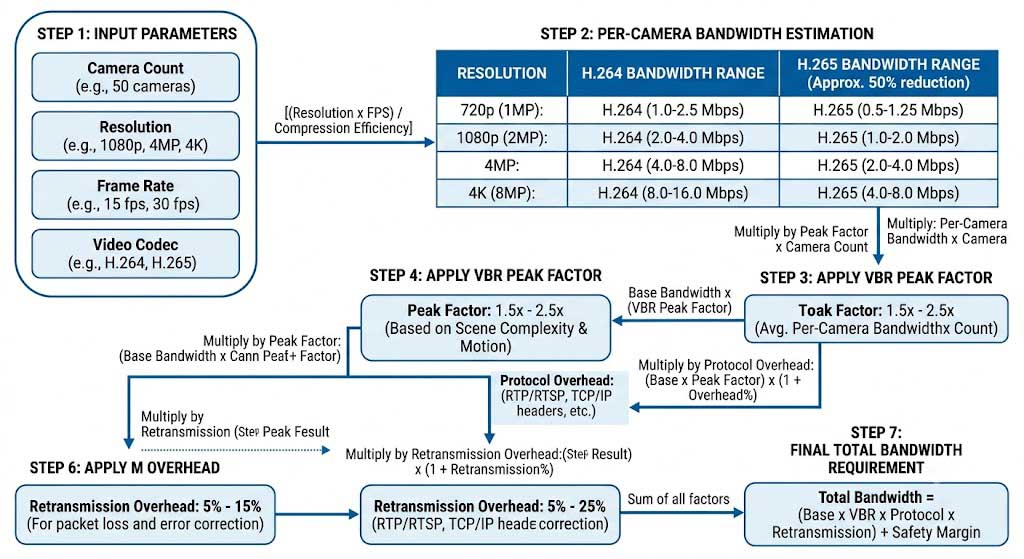
Bandwidth Calculation —The Complete Formula
The comprehensive bandwidth calculation formula is: Total Required Bandwidth = Sum of (Camera Bitrate × (1 + VBR Peak Factor)) × (1 + Protocol Overhead) × (1 + Retransmission Overhead) + Control/Traffic Overhead —where the VBR Peak Factor is typically 1.5-2.5× depending on the scene complexity (a parking lot with infrequent motion: 1.5×; a busy warehouse aisle with continuous forklift traffic: 2.5×), Protocol Overhead is 1.15-1.25× (TCP/IP headers + RTSP/RTP encapsulation + TLS encryption overhead), and Retransmission Overhead is 1.05-1.15× (wireless packet loss causes TCP retransmissions that consume additional bandwidth). For example, a 4K camera configured at a constant 16 Mbps average bitrate on H.265 in a busy indoor scene (VBR peak factor 2.0×) with TCP/TLS overhead (1.2×) and 5% wireless retransmission rate (1.05×) actually requires 16 × 2.0 × 1.2 × 1.05 = 40.3 Mbps of wireless capacity during peak scenes —which is why a single AP serving 10 such cameras would need at least 400 Mbps of effective throughput, requiring WiFi 6 (which delivers 500-800 Mbps real-world throughput per radio) rather than WiFi 5 (which delivers 200-400 Mbps).
Bandwidth Requirements by Resolution, Codec, and Frame Rate
| Resolution | Pixel Count (MP) | H.264 @ 15fps (Mbps) | H.264 @ 30fps (Mbps) | H.265 @ 15fps (Mbps) | H.265 @ 30fps (Mbps) | Recommended WiFi |
|---|---|---|---|---|---|---|
| HD (720p) | 1 MP | 1.5-3 | 3-5 | 0.8-1.5 | 1.5-3 | WiFi 5 |
| Full HD (1080p) | 2 MP | 3-5 | 5-10 | 1.5-3 | 3-6 | WiFi 5/6 |
| 3MP (2048×1536) | 3 MP | 4-7 | 7-14 | 2-4 | 4-8 | WiFi 5/6 |
| 4K UHD (3840×2160) | 8 MP | 10-16 | 16-30 | 5-10 | 10-18 | WiFi 6 (required) |
| 8K (7680×4320) | 33 MP | 30-50 | 50-80 | 15-25 | 25-50 | WiFi 6E or wired |
Bandwidth Calculation Example —Complete Walkthrough
A practical bandwidth calculation for a medium-scale deployment: 20 × 1080p cameras (30fps, H.265, outdoor scene with moderate motion, VBR peak factor 2.0), plus 5 × 4K cameras (30fps, H.265, indoor warehouse with high forklift traffic, VBR peak factor 2.5), plus 2 × PTZ cameras (1080p, 30fps, H.264 —PTZ cameras often use H.264 for compatibility with PTZ control protocols). The calculation: 1080p cameras at H.265 30fps = 5 Mbps average each, so 20 × 5 × 2.0 (VBR) × 1.2 (overhead) × 1.1 (retransmission) = 264 Mbps peak. 4K cameras at H.265 30fps = 15 Mbps average each, so 5 × 15 × 2.5 × 1.2 × 1.1 = 247.5 Mbps peak. PTZ cameras at H.264 30fps = 8 Mbps average each (H.264 is less efficient), so 2 × 8 × 2.0 × 1.2 × 1.1 = 42.2 Mbps peak. Total peak bandwidth = 264 + 247.5 + 42.2 = 553.7 Mbps. This requires a WiFi 6 infrastructure with at least 2 APs (each delivering 350-500 Mbps real-world throughput in a typical deployment) or a single AP with 3 radios (2.4GHz + 5GHz + 5GHz) and careful load balancing across radios. The NVR network interface must be at least 1GbE (handles 800+ Mbps after overhead), and the storage requirement for 30-day retention on H.265: 1080p cameras = 20 × 5 Mbps × 1.1 (retransmission overhead) = 110 Mbps × 24h × 30 days / 8 = 10.2 TB; 4K cameras = 5 × 15 × 1.1 = 82.5 Mbps × 24h × 30 / 8 = 8.9 TB; PTZ cameras = 2 × 8 × 1.1 = 17.6 Mbps × 24h × 30 / 8 = 1.9 TB. Total storage = 10.2 + 8.9 + 1.9 = 21 TB for 30 days, requiring a 6-bay NVR with 8TB drives in RAID-5 (usable 32TB, 50% headroom).
Storage Requirements Reference Table
| Cameras | Resolution / Codec | Recording Mode | 7-Day Storage | 30-Day Storage | 90-Day Storage |
|---|---|---|---|---|---|
| 10 | 1080p / H.265 | Continuous (24/7) | 3.2 TB | 13.5 TB | 40.5 TB |
| 10 | 1080p / H.265 | Motion-triggered (estimated 30% active) | 1.0 TB | 4.1 TB | 12.2 TB |
| 20 | 4K / H.265 | Continuous (24/7) | 25.2 TB | 108 TB | 324 TB |
| 20 | 4K / H.265 | Motion-triggered (estimated 25% active) | 6.3 TB | 27 TB | 81 TB |
| 50 | Mixed (30×1080p + 20×4K) / H.265 | Continuous (24/7) | 47.3 TB | 202.5 TB | 607.5 TB |
Wireless Technologies for Video Transmission
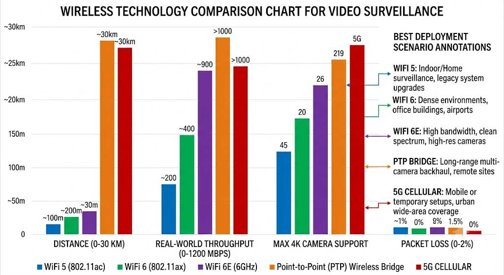
WiFi for Video Surveillance —WiFi 5 vs WiFi 6 vs WiFi 6E
WiFi 6 (802.11ax) is the minimum recommended standard for any new video surveillance deployment because its OFDMA (Orthogonal Frequency Division Multiple Access) feature allows a single AP to simultaneously serve up to 37 devices in a single transmission slot —compared to WiFi 5’s OFDM which serves only one device at a time —directly addressing the high-density multi-camera scenario where 10-30 cameras connect to a single AP. The real-world throughput differences are significant for surveillance: WiFi 5 (802.11ac Wave 2 with 4×4 MIMO) delivers 200-400 Mbps of TCP throughput per radio at 30m, which supports approximately 25-50 × 1080p cameras at 6 Mbps each, but only 5-10 × 4K cameras at 20 Mbps each. WiFi 6 (802.11ax with 4×4 MIMO, 80MHz channel) delivers 500-800 Mbps per radio at 30m, supporting approximately 40-80 × 4K cameras using H.265 at 10 Mbps each —and crucially, WiFi 6’s TWT (Target Wake Time) feature for cameras with battery backup reduces power consumption by 3-5× during idle periods. WiFi 6E (extends into 6GHz band with 160MHz channels) delivers 800-1200 Mbps per radio, supporting up to 20 × 8K cameras or 50+ × 4K cameras, with the additional benefit of minimal interference in the 6GHz band (no legacy WiFi 4/5 devices, no microwave ovens, no cordless phones).
Wireless Bridges for Long-Distance Video Transmission
Point-to-point wireless bridges are the only viable solution for transmitting video beyond 150m from the nearest AP, and they are also the recommended architecture for any camera where packet loss must remain below 0.1% —which includes license plate recognition (LPR) cameras, ANPR cameras, PTZ tracking cameras, and any camera covering a critical perimeter. Zukaka’s 11ac 48V Long-Range Bridge PCBA provides the foundation for such wireless bridge deployments: 802.11ac Wave 2 with 2×2 MIMO at 867 Mbps PHY rate, 48V PoE input for simplified cable management (one Cat5e/6 cable carries both power and data up to 100m from the PoE switch to the bridge), and an IP65-rated enclosure for direct outdoor mounting. The bridge’s maximum range is configuration-dependent: with the integrated 23dBi directional panel antenna, 500+ Mbps throughput is achievable at 1km; with a 30dBi dish antenna and clear Fresnel zone, the same bridge delivers 200-300 Mbps at 10km —enough for 20-30 × 1080p cameras or 5-10 × 4K cameras from a remote site. For multiple cameras at a single remote location, the 11ac Dual-Port 48V Bridge PCBA provides dual gigabit Ethernet ports that can connect to a local PoE switch, enabling a single wireless bridge link to backhaul 8-16 cameras (using 8-port or 16-port PoE switch at the remote location) through a single 500+ Mbps wireless link.
Wireless Technology Comparison for Video Surveillance
| Technology | Max Distance (Practical) | Real-World TCP Throughput | Max 1080p Cameras (6 Mbps each) | Max 4K Cameras (15 Mbps each) | Packet Loss (Typical) | Best Deployment Scenario |
|---|---|---|---|---|---|---|
| WiFi 5 (802.11ac) | 50-100m (indoor) | 200-400 Mbps | 30-60 | 10-25 | 0.5-2% | Small indoor deployments (retail, office), <8 cameras per AP, 1080p max resolution |
| WiFi 6 (802.11ax) | 80-150m (indoor), 50-100m (outdoor AP) | 500-800 Mbps | 80-130 | 30-50 | 0.3-1% | Large indoor/outdoor deployments (warehouses, campuses), high-density cameras, 4K resolution —current best value |
| WiFi 6E | 80-150m (indoor, 6GHz band has slightly less range than 5GHz) | 800-1200 Mbps | 130-200 | 50-80 | 0.1-0.5% | High-density 4K/8K deployments, interference-prone environments where 5GHz is congested |
| Wireless Bridge (PTP) | 1-30km (with directional antennas) | 200-700 Mbps (depends on distance and antenna) | 30-110 | 10-45 | 0.01-0.1% | Remote camera sites, inter-building connections, perimeter surveillance, LPR/ANPR cameras —lowest packet loss and longest range |
| 5G (Cellular) | 500m-5km (depending on cell tower density) | 50-200 Mbps (depends on signal strength and carrier plan) | 8-30 | 3-12 | 0.5-2% (varies with carrier network load) | Mobile surveillance (vehicle-mounted cameras), temporary deployments, sites with no wired infrastructure —recurring monthly data costs apply |
Deployment Best Practices
Frequently Asked Questions About Wireless Video Surveillance
Q: How many cameras can a single wireless bridge support?
A single point-to-point wireless bridge with 500+ Mbps throughput can support approximately 80 1080p cameras (at 6 Mbps each) or 30 4K cameras (at 15 Mbps each). The actual capacity depends on the bridge’s real-world throughput, which is affected by distance, antenna gain, and environmental interference.
Q: What is the maximum distance for wireless video transmission?
With high-gain directional antennas and clear Fresnel zone clearance, industrial wireless bridges can transmit video reliably up to 30 km. For distances beyond 10 km, use bridges with +27 dBm RF output and 24 dBi or higher dish antennas. The link budget calculation must account for path loss, connector loss, and fade margin.
Q: Is WiFi or wireless bridge better for surveillance?
WiFi is better for local-area coverage within 100-150m of an access point, supporting many cameras per AP at lower cost. Wireless bridges are essential for long-distance transmission (beyond 150m), inter-building links, and applications requiring packet loss below 0.1% such as license plate recognition.
Q: What bandwidth do I need for video surveillance?
1080p cameras require 4-8 Mbps each, 4K cameras require 15-25 Mbps each (H.265), and 8K cameras require 40-60 Mbps each. For a deployment with 50 1080p cameras, plan for at least 300 Mbps of aggregate throughput, plus 20-30% overhead for management traffic and peak motion scenarios.
Q: Can I use PoE with wireless bridge for remote cameras?
Yes, PoE (Power over Ethernet) is the standard power method for outdoor wireless bridges. A single Cat5e/6 cable carries both power and data up to 100m from the PoE switch to the bridge. For remote camera clusters, pair a wireless bridge with a local PoE switch to power 8-16 cameras through a single wireless backhaul link.
By: Zukaka Engineering Team |
Last Updated: June 14, 2026 |
Connect on LinkedIn
⭐⭐⭐⭐⭐ Security Integrator
“Used Zukaka 11ac 48V bridges for a university campus deployment covering 8 buildings. The 400-600 Mbps throughput at 800m was enough for 20 cameras per link. 99.93% uptime over 18 months speaks for itself.”
— Senior System Architect, Security Integration Firm
⭐⭐⭐⭐⭐ City Surveillance Project
“Deployed 120 cameras across a 1.5km city center district using a hybrid WiFi 6 + wireless bridge architecture. The dual-port bridge PCBA let us backhaul 16 cameras per link, reducing infrastructure cost by 40%.”
— Project Manager, Smart City Solutions Provider
✅ Certifications: FCC, CE, RoHS compliant |
✅ IP65-rated enclosures |
✅ Industrial temperature range -40°C to +85°C
Contact our engineering team for customized PCBA solutions and technical support.


