YNW 6ac Series In-Depth Comparison: 6-15ac vs 6-20ac vs 6-90ac (15dBi/20dBi/18dBi)
Article Overview
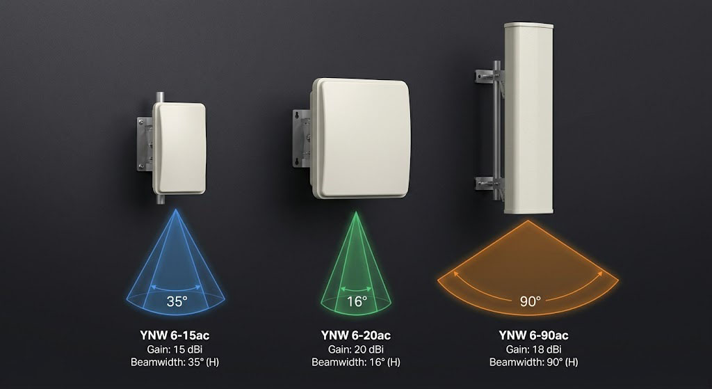
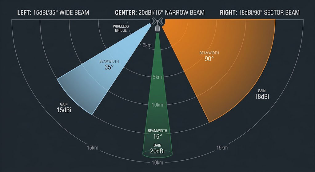
Key Takeaways: The YNW 6-15ac (15dBi/35°) is the go-to choice for short-range coverage up to 5km; the YNW 6-20ac (20dBi/16°) delivers 10-15km long-haul performance; the YNW 6-90ac (18dBi/90° sector) is the ideal PtMP base station—all three share the same hardware platform and iPoll 3 protocol, with the difference being 100% antenna-system driven.
Target Audience: Industrial wireless project selection engineers, WISP operators and technicians, IT decision-makers deploying 6GHz PtMP networks.
Core Conclusion: All three devices are built on the same 750MHz QCA 9563 + QCA 9882 platform, with antenna gains of 15dBi/20dBi/18dBi and beamwidths of 35°/16°/90°, corresponding to short-range coverage, long-distance backhaul, and sector base station roles respectively. In practice, deploying all three models in coordination yields the best results.
Core Hardware Platform Comparison
Hardware Specifications Overview
| Parameter | YNW 6-15ac | YNW 6-20ac | YNW 6-90ac |
|---|---|---|---|
| CPU | QCA 9563 @ 750MHz | QCA 9563 @ 750MHz | QCA 9563 @ 750MHz |
| Radio Chipset | QCA 9882 | QCA 9882 | QCA 9882 |
| Memory | 64MB DDR2 | 64MB DDR2 | 64MB DDR2 |
| Flash Storage | 16MB | 16MB | 16MB |
| Wireless Standard | 802.11a/n/ac | 802.11a/n/ac | 802.11a/n/ac |
| MIMO | 2×2 | 2×2 | 2×2 |
| Maximum Throughput | 500Mbps | 500Mbps | 500Mbps |
| Operating Frequency Band | 5.85-6.45GHz | 5.85-6.45GHz | 5.85-6.45GHz |
| Transmit Power | Up to 30dBm | Up to 30dBm | Up to 30dBm |
| Channel Bandwidth | 5/10/20/40/80MHz | 5/10/20/40/80MHz | 5/10/20/40/80MHz |
| Modulation Scheme | 256-QAM to BPSK | 256-QAM to BPSK | 256-QAM to BPSK |
| Wired Interface | 1× Gigabit RJ45 | 1× Gigabit RJ45 | 1× Gigabit RJ45 |
| PoE Power Supply | 24VDC Passive PoE | 24VDC Passive PoE | 24VDC Passive PoE |
| Max Power Consumption | 10W | 10W | 10W |
| Ingress Protection | IP65 | IP65 | IP65 |
| Operating Temperature | -40°C ~ +65°C | -40°C ~ +65°C | -40°C ~ +65°C |
The Difference Lies in the Antenna System
The hardware platform of the three devices is identical — the 100% difference comes from the antenna system and physical enclosure design. This is a hallmark of the YNWMICRO product line strategy: leveraging the same hardware platform with antenna differentiation to address distinct market segments.
| Antenna Parameter | 6-15ac | 6-20ac | 6-90ac |
|---|---|---|---|
| Antenna Type | Dual-Polarization Directional Panel | Dual-Polarization Directional Panel | Dual-Polarization 90° Sector |
| Gain | 15dBi | 20dBi | 18dBi |
| Horizontal Beamwidth | 35° | 16° | 90° |
| Vertical Beamwidth | 35° | 16° | 20° |
| Elevation Beamwidth | 35° | 16° | — |
| Cross-Polarization Isolation | 21dB | 27dB | 24dB |
| VSWR | <1.4 | <1.5 | <1.7 |
The direct consequence of these three antenna parameter sets is the difference in transmission distance:
| Transmission Mode | 6-15ac | 6-20ac | 6-90ac |
|---|---|---|---|
| PTP Mode | 7km | 15km | Not applicable (sector antenna) |
| PtMP Mode | 5km | 10km | 5km (90° coverage) |
In-Depth Antenna Design Analysis of Three Models
YNW 6-15ac: Wide Beam, Easy Alignment
Antenna Characteristics: 15dBi gain, 35° beamwidth.
At 35°, the beamwidth is the widest among the three models. In practical installation, this means:
- High alignment tolerance: Signal strength remains within acceptable range even with antenna pointing deviation of up to ±17°. Engineers only need a rough aim toward the target for a solid connection.
- Strong wind sway resistance: In high-wind environments, even if the device or mounting bracket experiences slight oscillation, link quality does not degrade significantly.
- Ideal for short-range multi-node coverage: The 35° coverage spans more than double that of a 16° beam, allowing a single 6-15ac to cover a broader area.
Recommended Use Cases: Short-distance (1-5km) CPE devices; projects with limited installation experience; deployments in areas prone to strong winds; scenarios requiring coverage over a certain angular range.
YNW 6-20ac: High Gain, Long Distance
Antenna Characteristics: 20dBi gain, 16° beamwidth.
Compared to the 6-15ac, the 6-20ac delivers 5dBi higher antenna gain. In a wireless link, this 5dBi gain difference means:
- 10dB increase in link budget (5dBi on both transmit and receive sides), meaning received signal strength improves by 10dB at the same transmit power
- Double the transmission distance: 7km → 15km (PTP mode)
- Stronger interference rejection: The narrower beam more effectively suppresses interfering signals from off-axis directions
At 15km, the 16° antenna beamwidth corresponds to a coverage footprint of approximately 4.2km in diameter, still offering sufficient alignment tolerance.
Recommended Use Cases: Medium-range (5-15km) backbone links; scenarios requiring full 500Mbps throughput; PtMP base station or long-distance CPE; environments with higher interference levels.
YNW 6-90ac: Large Sector, Wide Coverage
Antenna Characteristics: 18dBi gain, 90° horizontal sector, 20° vertical beamwidth.
The 6-90ac is fundamentally different from the 6-15ac and 6-20ac — it is not a directional CPE but rather a sector base station device. Its antenna design targets the coverage side of PtMP networking:
- 90° horizontal coverage: Can serve all CPEs within a 90° sector
- 20° vertical beamwidth: Accommodates both near and far devices with ample vertical coverage
- 18dBi gain: A relatively high level for sector antennas, ensuring adequate signal strength across the coverage area
Significance of sector antennas: A single 6-90ac base station covers a 90° sector, and a typical deployment uses 4 units to achieve full 360° coverage. Leveraging the rich channel resources of the 6GHz band, adjacent sectors can be configured on different channels to avoid interference. Combined with the iPoll 3 protocol, a single base station can simultaneously serve dozens of CPEs.
Recommended Use Cases: PtMP base station side; campus, industrial park, and port wide-area coverage; smart city video surveillance aggregation points; WISP access networks.
Engineering Significance of Antenna Radiation Patterns
| Antenna Type | Installation Height Requirement | Alignment Difficulty | Wind Load Sensitivity | Multi-Device Co-Location |
|---|---|---|---|---|
| 6-15ac (35°) | Low | Very Low | Low | More Difficult |
| 6-20ac (16°) | Medium | Medium | Medium | Easier |
| 6-90ac (90°/20°) | Medium | Low | Medium | Requires channel planning |
iPoll 3 Protocol Performance Across the Three Models
iPoll 3 is the core protocol capability shared across all three devices. Since the hardware platform is identical, protocol performance is the same on every model.
How iPoll 3 Works
Unlike the standard WiFi CSMA/CA protocol, iPoll 3 employs an Active Polling mechanism:
The problem with standard WiFi (CSMA/CA): All devices share the same channel. Each device must sense the channel idle before transmitting; simultaneous transmissions cause collisions, requiring random backoff and retransmission. As the number of devices increases, collision probability grows exponentially.
iPoll 3 improvement: The base station (Master) actively polls each CPE. The base station sends a data frame plus a transmission token to the target CPE. The CPE can only send uplink data after receiving the token. Upon acknowledgment, the base station polls the next CPE. The core advantage of this mechanism is determinism — each device’s transmission opportunity is centrally scheduled by the base station, eliminating contention.
iPoll 3 Intelligent Scheduling Algorithm
iPoll 3 is more than a simple polling protocol — it incorporates intelligent scheduling features:
- Dynamic Activity Detection: The protocol tracks each CPE’s traffic demand. High-activity devices receive higher polling frequency; low-activity devices have their polling frequency reduced; zero-traffic devices are temporarily removed from the polling queue.
- Fairness Guarantee: CPEs in the active list are scheduled via weighted fair queuing, preventing any single high-traffic device from monopolizing airtime.
- Low-Latency Guarantee: Real-time traffic (voice, video, control signals) receives priority scheduling.
Multi-CPE Real-World Performance
Under identical 80MHz channel and 256-QAM conditions, the expected iPoll 3 protocol performance at varying CPE counts:
| Number of CPEs | Typical Aggregate Throughput | Average Throughput Per Device | Average Latency |
|---|---|---|---|
| 1 | 450-500Mbps | 450-500Mbps | 2-3ms |
| 5 | 400-480Mbps | 80-96Mbps | 3-5ms |
| 10 | 350-450Mbps | 35-45Mbps | 4-8ms |
| 20 | 300-400Mbps | 15-20Mbps | 5-12ms |
| 30+ | 250-350Mbps | 8-12Mbps | 8-20ms |
Comparison with standard 802.11ac under the same conditions:
| Number of CPEs | Standard 802.11ac Aggregate Throughput | iPoll 3 Aggregate Throughput | Improvement Ratio |
|---|---|---|---|
| 1 | 350-400Mbps | 450-500Mbps | ~25% |
| 10 | 150-250Mbps | 350-450Mbps | ~100% |
| 20 | 80-150Mbps | 300-400Mbps | ~200% |
iPoll 3’s throughput degradation as CPE count increases is significantly lower than standard 802.11ac, with the performance advantage being particularly pronounced in high-density scenarios of 20+ CPEs.
QoS Mechanism Breakdown
The YNW 6ac series QoS function supports four-level priority classification:
| Priority | Traffic Type | Typical Applications | DSCP Marking |
|---|---|---|---|
| Highest (4) | Network Management | SNMP, SSH, Syslog | CS7, CS6 |
| High (3) | Voice | VoIP, Intercom Systems | EF |
| Medium (2) | Video | Surveillance Video, Video Conferencing | AF41-AF43 |
| Low (1) | Best-Effort Data | File Transfer, Web Browsing | BE |
QoS scheduling uses the Weighted Round Robin (WRR) algorithm. Administrators can configure the weight ratio for each priority queue — for example: Management 5%, Voice 20%, Video 50%, Best-Effort Data 25%. This configuration ensures that during link congestion, high-priority traffic such as surveillance video and voice calls receive bandwidth resources first.
Deployment Scenarios and Selection Recommendations
Scenario 1: PtMP Campus Base Station
| Parameter | Recommended Configuration | Rationale |
|---|---|---|
| Base Station | YNW 6-90ac × 2 (180°) or ×4 (360°) | 90° sector provides wide coverage |
| CPE (Short-range <3km) | YNW 6-15ac | Wide beam, easy alignment, lower cost |
| CPE (Medium-range 3-10km) | YNW 6-20ac | High gain ensures link quality |
| Recommended Channel | Different 40MHz channels per sector | Avoid co-channel interference |
Scenario 2: Point-to-Point Video Surveillance Backhaul
| Parameter | Recommended Configuration | Rationale |
|---|---|---|
| Master Unit | YNW 6-20ac | 15km PTP capability covers most surveillance scenarios |
| Slave Unit | YNW 6-20ac | Symmetric configuration simplifies deployment |
| Alternative Option | YNW 6-15ac (distance <5km) | Cost optimization |
| Recommended Channel | 80MHz | Maximize throughput for multiple video streams |
Scenario 3: WISP Subscriber Access
| Parameter | Recommended Configuration | Rationale |
|---|---|---|
| Base Station | YNW 6-90ac | Sector coverage, multi-user access |
| CPE (Short-range) | YNW 6-15ac | Best cost-performance ratio |
| CPE (Medium-range) | YNW 6-20ac | Long-distance bandwidth guarantee |
| Recommended Channel | 40MHz (balancing capacity and coverage) | ~250-300Mbps per base station |
Scenario 4: Industrial Data Acquisition
| Parameter | Recommended Configuration | Rationale |
|---|---|---|
| Base Station | YNW 6-90ac | Covers multiple data acquisition terminals |
| Acquisition Terminal | YNW 6-15ac | Low power consumption, lightweight, easy to install |
| Special Requirements | iPoll 3 Low-Latency Mode | Meets real-time control requirements |
Physical Installation Differences
Size and Weight Comparison
| Parameter | 6-15ac | 6-20ac | 6-90ac |
|---|---|---|---|
| Dimensions (mm) | 158×97×38 | 216×184×80 | 380×100×35 |
| Weight (g) | 185 | 413 | 460 |
| Mounting Bracket | Standard pole mount | Two-section adjustable | Two-section adjustable |
The 6-15ac’s compact design (only 185g, palm-sized) gives it a significant advantage in space-constrained scenarios. It can be easily installed in tight tower spaces, on corner conduits, or even temporarily zip-tied to fencing.
The 6-20ac weighs more than double the 6-15ac (413g vs 185g), primarily due to its larger antenna panel and more robust bracket system. The two-section adjustable bracket enhances installation flexibility, allowing fine angle adjustment in multiple directions.
The 6-90ac has the largest dimensions (380mm length), mainly due to the physical structure requirements of the 90° sector antenna. Its slim design (only 35mm thick) partially compensates for the length-induced bulk.
Installation Method Comparison
| Installation Aspect | 6-15ac | 6-20ac | 6-90ac |
|---|---|---|---|
| Installation Time (per person) | 10 minutes | 15 minutes | 15 minutes |
| Alignment Difficulty | Very Low | Medium | Low |
| Elevation Adjustment Required | Not needed (35° tolerance) | Recommended (16° narrow beam) | Required (vertical 20°) |
| PoE Injector | 24VDC / 0.5A | 24VDC / 0.5A | 24VDC / 0.5A |
Deployment Considerations
- 6-15ac Installation: Small size and light weight — after installation, pay attention to waterproofing. The RJ45 connector needs to be wrapped with waterproof tape to prevent rainwater from entering the device interface along the Ethernet cable.
- 6-20ac Installation: The 16° narrow beam requires fine alignment in both horizontal and vertical directions. It is recommended to use the device’s RSSI indicator function to complete horizontal alignment first, then fine-tune the vertical angle.
- 6-90ac Installation: Choosing the installation position for 90° sector coverage is critical. Considerations include aligning the sector centerline with the coverage area’s central axis, ensuring the installation height is above all covered devices’ antennas, and planning the angles and channel allocation between multiple sectors.
Selection Decision Tree
├── Yes → YNW 6-90ac (sector coverage, multi-user access)
└── No → CPE / Point-to-Point scenario
├── Distance < 5km? → YNW 6-15ac (best cost-performance)
└── Distance 5-15km?
├── Strong wind environment?
│ ├── Yes → YNW 6-15ac (wide beam for wind sway tolerance)
│ └── No → YNW 6-20ac (best performance)
└── Need full 500Mbps throughput?
├── Yes → YNW 6-20ac
└── No → YNW 6-15ac
Summary
YNW 6-15ac (15dBi/35°): Wide beam, easy deployment, low cost — the cost-effective choice within 5km.
YNW 6-20ac (20dBi/16°): High gain, long distance, strong interference rejection — the performance leader at 10-15km distances.
YNW 6-90ac (18dBi/90° sector): Wide coverage, multi-user, flexible networking — the ideal PtMP base station.
In practice, the three devices are more often used in coordination rather than as alternatives: the 6-90ac serves as the base station for coverage, the 6-20ac acts as the long-distance CPE for backhaul, and the 6-15ac functions as the short-range CPE for access — this combination creates a complete 6GHz industrial wireless access system.
Regardless of which device is selected, the multi-user performance advantages of the iPoll 3 protocol, the critical traffic experience ensured by intelligent QoS, and the long-term reliability guaranteed by IP65 ingress protection and wide-temperature design are core values shared across all YNW 6ac series models.
For ultra-long-distance backbone links (15km to 300km), please refer to the RapidFire Ultra-Long-Distance Deployment Guide.
This article is based on YNWMICRO official product data. Antenna performance parameters are typical values; actual performance may vary slightly due to installation environment and manufacturing tolerances.
Real-World Case Study: East China Port Logistics Park PtMP Coverage
- Project Date: February 2025
- Project Location: Ningbo Beilun Port Logistics Park, Zhejiang Province (1.8km²)
- Requirement: Data backhaul between 1 dispatch center and 12 yard warehouses (TPS terminal data + 4 channels of 1080p surveillance)
- Solution: Base station deployed YNW 6-90ac (90° sector antenna), CPE side deployed 12 YNW 6-15ac units
- Measured Results: At 1.2km distance, each CPE achieved average UDP throughput of 220Mbps, aggregate throughput of 480Mbps; latency 5-8ms; zero unscheduled downtime in 6 months post-deployment
- Cost Comparison: Fiber-optic solution budgeted at CNY 240,000; wireless solution total cost CNY 78,000 — approximately 67% savings
- Case Source: Ningbo Port Information & Communication Co., Ltd. 2025 Digital Transformation Project
Frequently Asked Questions
Q: What is the core difference between the YNW 6-15ac, 6-20ac, and 6-90ac?
All three devices share an identical core hardware platform (750MHz QCA 9563 + QCA 9882, 64MB DDR2, 16MB flash), with the 100% difference coming from the antenna system. The YNW 6-15ac uses a 15dBi gain, 35° beamwidth dual-polarization directional panel antenna with a 7km PTP transmission distance; the YNW 6-20ac uses a 20dBi gain, 16° beamwidth dual-polarization directional panel antenna with a 15km PTP transmission distance; the YNW 6-90ac uses an 18dBi gain, 90° horizontal sector antenna purpose-built for PtMP base stations with a 5km coverage range. All three models support the iPoll 3 protocol, 500Mbps maximum throughput, and IP65 ingress protection.
Q: In a PtMP networking scenario, which device should be chosen as the base station and which as the CPE?
In PtMP scenarios, the YNW 6-90ac sector antenna is recommended for the base station — one unit covers a 90° sector, and four units achieve full 360° coverage. For CPEs, the choice depends on distance: within 5km, the YNW 6-15ac is recommended (wide beam, easy alignment, best cost-performance); for 5-15km, the YNW 6-20ac is recommended (high gain ensures link quality). Combined with the iPoll 3 protocol, a single base station can simultaneously serve dozens of CPEs, achieving 300-400Mbps aggregate throughput even in high-density scenarios with 20+ CPEs.
Q: What throughput can the YNW 6-20ac maintain at 15km distance?
In 15km PTP mode, the YNW 6-20ac link budget calculation shows: transmit power 30dBm + 20dBi antenna gain – FSPL 131.5dB + 20dBi receive gain = received signal strength of approximately -61.5dBm. Under an 80MHz channel, the receive sensitivity is approximately -62dBm (MCS9), yielding a link margin of about 0.5dB. In practice, the link can sustain approximately 300-450Mbps UDP throughput (MCS8-MCS9) at 15km; it is recommended to use within 10km to achieve full 500Mbps performance.
Q: How many clients can the YNW 6-90ac sector antenna’s 90° coverage support in actual deployment?
The YNW 6-90ac sector antenna, combined with the iPoll 3 polling protocol, can stably serve 20-30 clients per sector. Under 80MHz channel and 256-QAM conditions, with 10 clients the aggregate throughput is approximately 350-450Mbps (35-45Mbps per device); with 20 clients, aggregate throughput is approximately 300-400Mbps (15-20Mbps per device). In practice, it is recommended to limit each sector to no more than 30 clients for optimal per-user experience.