Differences Between Wireless Bridges and Wireless Video Transmission Devices: A Full-Scenario Selection Guide Based on Zukaka Qualcomm QCA Series WiFi Modules
Summary: In wireless transmission scenarios such as security surveillance, industrial IoT, field inspection, and low-altitude UAVs, wireless bridges and wireless video transmission devices are easily confused. Although both can share WiFi RF modules at the hardware level, their product positioning, functional logic, QC certification, and applicable scenarios are fundamentally different. This article systematically breaks down the core differences among wireless bridges, WiFi-IP video transmission, and COFDM video transmission from three dimensions: product essence, RF QC, and SRRC certification. It details the device categories and core parameter advantages that can be developed from the full range of zukaka.com Qualcomm WiFi modules (e.g., QCA9984), and provides dual-standard selection solutions covering fixed surveillance, urban NLOS, vehicular, and airborne scenarios. It serves as a one-stop technical reference for equipment manufacturers and project integrators, from hardware selection to scenario implementation.
I. Core Concept: Wireless Bridge ≠ Wireless Video Transmission Device
A common misconception in the industry is that all 5.8GHz microwave wireless transmission devices are the same product category, and wireless bridges are used as wireless video transmission devices. In fact, a wireless bridge is a general-purpose network transmission device, while wireless video transmission is a dedicated video transmission device. Only some IP video transmission devices developed based on WiFi modules share standard WiFi RF hardware with wireless bridges. Their product attributes, QC standards, and application values are entirely different.
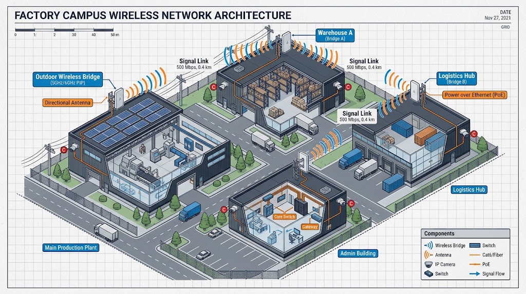
Figure 1: Core differences between wireless bridge and wireless video transmission devices
1.1 Product Essence and Core Functional Differences
Wireless Bridge: A wireless LAN Layer 2 bridging device based on the 802.11 standard WiFi protocol. Its core function is to replace wired Ethernet cables and achieve transparent transmission of IP packets across the network, regardless of whether the content is video, data, control commands, or ordinary network signals. It has no video encoding/decoding capability and is only responsible for network forwarding. Its core advantages are flexible networking, strong compatibility, and support for point-to-multipoint batch networking, focusing on general-purpose network interconnectivity.
Wireless video transmission devices fall into two major technical categories, both purpose-built for video transmission, with the core goal of ensuring a stable image, low latency, and smooth playback:
- WiFi-IP Video Transmission: Based on the standard 802.11 protocol and developed on WiFi modules, it adds video encoding/decoding and low-latency flow control optimization on top of network transmission, balancing video transmission and IP data passthrough with excellent cost-effectiveness;
- Private Protocol Video Transmission (COFDM): Uses non-standard WiFi protocols and proprietary modulation algorithms, incompatible with standard WiFi Layer 2 networking (although most devices support IP data passthrough). It focuses on resistance to occlusion, resistance to Doppler interference under mobility, and ultra-low latency, suited for professional-grade scenarios.
1.2 Interface, Performance, and Application Scenario Differences
| Comparison Dimension | Wireless Bridge | WiFi-IP Wireless Video Transmission (Zukaka WiFi module solution) | Private COFDM Professional Video Transmission |
|---|---|---|---|
| Core Interface | RJ45 Ethernet only | Ethernet + HDMI video port (extensible) | HDMI/SDI professional video port |
| Core Capability | IP data forwarding, Layer 2 networking | HD video low-latency transmission + bidirectional IP control data | Pure professional video transmission, ultimate stability and low latency |
| Video Processing | No encoding/decoding, no video optimization | Built-in H.264/H.265 codec, UDP video stream optimization | Dedicated video modulation/demodulation algorithm |
| Transmission Latency | Network forwarding latency, no video latency spec | 80-150ms (controllable low jitter) | 30-80ms (professional-grade ultra-low latency) |
| Applicable Scenarios | Campus/building networking, IPC network backhaul, general wireless bridging | Fixed line-of-sight surveillance, industrial IP video transmission, low-cost projects | Urban occlusion, vehicular/UAV high-speed mobility, film monitoring |
1.3 Core Differences in QC and Certification (Industry Pain Point)
Although the two share some RF hardware, their QC items, SRRC classifications, and bidding acceptance criteria are completely independent and reports cannot be interchanged:
- Wireless Bridge: Classified by SRRC as WLAN wireless LAN equipment. QC focuses on throughput, packet loss, networking stability, and DFS radar detection, with no video performance test items. It cannot participate in bidding as video transmission equipment;
- WiFi-IP Video Transmission: RF parameters are identical to bridges, but type testing must add video-specific tests (end-to-end latency, frame loss, PSNR picture quality, bitrate stability), which is the core basis for distinguishing bridges from IP video transmission;
- Private Protocol Video Transmission: Classified by SRRC as wireless video transmission equipment. It does not need to follow the 802.11 protocol or perform DFS detection, and is evaluated on multipath resistance, weak-signal video stability, and other application-specific metrics.
General RF Parameter Checklist: Transmit frequency, frequency tolerance, transmit power, EIRP (equivalent isotropic radiated power), occupied bandwidth (OBW), spectrum mask, ACLR (adjacent channel leakage ratio), spurious emissions, receive sensitivity, VSWR (voltage standing wave ratio), EVM (error vector magnitude).
1.3.1 WiFi-IP Video Transmission (802.11ac/ax, QCA9984 solution) Additional RF Items
The IP video transmission developed with Zukaka modules is classified by SRRC as WLAN equipment. On top of the general RF checklist, the following two items must be added (not required for private video transmission):
- DFS Radar Detection (5GHz U-NII band): Mandatory for 5.2G/5.3G bands. Upon detecting radar signals, the device must exit the channel and switch within a specified time to avoid interfering with meteorological/military radar.
- WiFi Protocol RF Compliance: 802.11 frame structure, preamble, OFDM modulation compliance testing; MIMO channel isolation (QCA9984 is 4×4 MIMO, engineering experience value ≥15~20dB, subject to module datasheet).
The RF test items for bridges and WiFi-IP video transmission are completely identical; the difference lies only in video service parameters, with no difference in the RF portion.
1.3.2 Private Protocol Video Transmission (COFDM etc., non-WiFi) Specific RF Items
- Modulation characteristics (COFDM subcarriers, constellation diagram EVM error vector magnitude);
- Bit error rate BER (distinct from WiFi’s PER packet error rate).
Private video transmission does not perform DFS or 802.11 protocol testing.
1.3.3 RF Derived Parameters (Commonly Used in Engineering/Production Lines, Not SRRC Mandatory)
- EVM Error Vector Magnitude: Measures modulation signal quality. Larger EVM means more severe distortion and a greater tendency to stall at long range. EVM limits are strongly correlated with modulation order (802.11ac spec): QPSK ≤-8dB, 16QAM ≤-13dB, 64QAM ≤-27dB, 256QAM ≤-32dB; insufficient EVM margin in high-rate modes is the main cause of long-range stalling.
- Channel Flatness: In-band signal amplitude fluctuation, typically required within ±2dB.
- MIMO Channel Balance (MIMO devices): Power consistency across multiple transceiver channels, difference ≤2dB.
- RF Latency: The transmission latency of the RF chain itself, only over-the-air latency (microsecond level), not equal to video end-to-end latency.
1.3.4 Concise RF Test Items Summary Table
| RF Indicator | WiFi-IP Video Transmission (QCA9984) | Private COFDM Video Transmission | SRRC Mandatory | Production Line Full Inspection |
|---|---|---|---|---|
| Center Frequency & Frequency Tolerance | ✅ | ✅ | ✅ | ✅ |
| Transmit Power / EIRP | ✅ | ✅ | ✅ | ✅ |
| Occupied Bandwidth OBW | ✅ | ✅ | ✅ | ✅ |
| Spectrum Mask | ✅ | ✅ | ✅ | ✅ |
| ACLR Adjacent Channel Leakage | ✅ | ✅ | ✅ | ✅ |
| Spurious Emissions | ✅ | ✅ | ✅ | ✅ |
| Receive Sensitivity | ✅ | ✅ | ✅ | ✅ |
| VSWR Standing Wave | ✅ | ✅ | ❌ Type, mandatory on production line | ✅ |
| EVM | ✅ | ✅ | ✅ | Sampling |
| DFS Radar Detection | ✅ | ❌ | ✅ (5G band) | Firmware feature sampling |
| MIMO Channel Isolation / Balance | ✅ (MIMO modules) | Depends on solution | ✅ Type | Sampling |
II. Zukaka Full Series WiFi Modules: Developable Device Categories and Core Parameter Advantages
The full zukaka.com range is equipped with Qualcomm QCN/QCA series industrial-grade chips, covering WiFi5/WiFi6/WiFi6E/WiFi7 in mainstream MiniPCIe/M.2 packages. They are the core preferred hardware for wireless bridges, WiFi-IP video transmission, and industrial wireless terminals, combining high power, high bandwidth, high stability, and low cost, suitable for consumer, enterprise, and industrial full-scenario device development. All WiFi module products can be found at the Zukaka WiFi Module Product Center.
2.1 Module Core Technology System
- Protocol Iteration: WiFi5 (802.11ac), WiFi6 (802.11ax), WiFi6E, WiFi7 (802.11be), with physical layer peak rates spanning 433Mbps (WiFi5 1×1 80MHz) to 11530Mbps (WiFi7 320MHz+MLO theoretical peak);
- Band Combinations: Single 2.4G / single 5G, dual-band 2.4G+5G, tri-band 2.4G+5G+6G, balancing coverage, speed, and interference resistance;
- Hardware Form Factor: MiniPCIe (preferred for engineering equipment), M.2 (compact terminal devices);
- Tiered Scenarios: Consumer grade, enterprise high-density grade, industrial wide-temperature-range high-power grade.
2.2 Developable Core Device Categories
Powered by Zukaka Qualcomm WiFi modules, you can quickly bring commercial devices to market without self-developing the RF layer, significantly compressing the R&D cycle and hardware cost.
2.2.1 Industrial Wireless Bridge Equipment (Mature Mass-Production Solution)
Zukaka offers both WiFi modules for self-developed bridges and plug-and-play industrial wireless bridge end products. The full WiFi5/WiFi6 module lineup can directly support outdoor/indoor wireless bridge development, with point-to-point and point-to-multipoint networking, suitable for long-distance network backhaul in factories, campuses, mines, tower cranes, and similar scenarios. Representative models and parameters (from the Zukaka Product Center):
- WLE1216VX (QCA9984): 4×4 MU-MIMO dual-band 2.4G+5G, peak 1733Mbps, transmit power 26dBm, MiniPCIe package, suitable for mid-to-long-range outdoor bridges;
- WLE1216VX-I (QCA9994): 4×4 MU-MIMO dual-band 2.4G+5G, peak 1733Mbps, transmit power 26dBm, industrial wide-temperature-range version;
- WLE900V5-27ESD: 3×3 MIMO 5G single-band high-power version, 1300Mbps rate, 32dBm transmit power, suitable for ultra-long-range point-to-point bridges;
- WLE600V5-27ESD: 2×2 MIMO 5G single-band high-power version, 867Mbps rate, 30dBm transmit power, cost-effective long-range solution;
- WLE900VX-I (QCA9890): 3×3 MIMO dual-band, 1300Mbps rate, 25dBm power, preferred for small-to-medium scenario bridges.
Bridge end products can be selected directly from the Industrial Wireless Bridge series. Representative models: YNW 5-20ac (5GHz 802.11ac, 500+Mbps, IP66), YNW 5-20ax (5GHz 802.11ax, IP67, PTP/PTMP), YNW 5ac (5GHz 802.11ac, PTP 20km, N-type connector), YNW 5-90ax (5GHz 802.11ax, 1500Mbps, IP67 sector base station), YNWPTP 5-23 RapidFire (5GHz, 700+Mbps, IP67 PtP).
Typical Application Scenarios for Industrial Wireless Bridges (based on Zukaka Industrial Wireless Network product model features):
| Application Scenario | Recommended Models | Key Feature Match |
|---|---|---|
| Inter-building network interconnection in plants/campuses, IPC surveillance backhaul | YNW 5-20ac, YNW 5-20ax | 500+Mbps throughput, IP66/IP67 protection, point-to-multipoint aggregation |
| Ultra-long-range point-to-point backhaul in mines, tower cranes, ports (10~20km) | YNW 5ac (PTP 20km), YNWPTP 6-25 RapidFire | N-type connector for external high-gain antenna, long-distance link budget |
| High-density campus/school multi-point access, sector coverage | YNW 5-90ax (1500Mbps sector base station), YNW 5-90ac | Sector antenna, high bandwidth, multi-user access |
| High-rate low-latency backhaul (video conferencing, industrial control) | YNWPTP 5-23 RapidFire (700+Mbps, IP67) | High throughput, low jitter, stable PtP link |
| 6GHz clean band dedicated backhaul (avoiding 5.8G congestion) | YNWPTP 6-N RapidFire, YNWPTP 6-25 RapidFire | 6GHz band, less interference, larger bandwidth |
| Rapid deployment, temporary emergency networking | YNW 5-15ac, YNW 5-23ax | Plug-and-play, flexible PTP/PTMP networking |
Selection Guidelines: For long-distance point-to-point, prioritize N-type connectors + high-gain directional antennas; for multi-point aggregation, prioritize sector base stations; for high-density environments, prioritize 6GHz or WiFi6 models to reduce co-channel interference.
Key factory QC items for bridge end products: appearance and power-up check, full RF testing, network throughput, Layer 2 forwarding, WDS networking, high/low-temperature and humidity testing, lightning protection, IP protection.
2.2.2 WiFi-IP Wireless Video Transmission Equipment (High Cost-Effective Custom Solution)
Zukaka modules are the preferred RF hardware for IP video transmission. Combined with a video codec baseboard + custom low-latency firmware, commercial IP wireless video transmission can be developed as an alternative to high-priced private protocol video transmission, suitable for fixed line-of-sight video transmission scenarios, supporting bidirectional transparent transmission of HD video + PTZ control data. Typical video transmission categories that can be implemented include: fixed-site wireless surveillance video transmission (plant/tower crane/mine IPC backhaul), broadcast-grade low-latency monitoring video transmission, and short-range FPV video transmission. There are mature commercial cases in China—some wireless video transmission devices from brands such as MOMA are developed based on Qualcomm QCA series WiFi chips (pin-compatible solution with Zukaka modules), achieving 1080P60 HD video with 80~150ms low-latency transmission, fully validating the mass-production feasibility and market acceptance of this solution.
Development Key Points: Disable redundant WiFi retransmission, optimize UDP video buffers, implement adaptive bitrate, and reduce end-to-end video latency.
Besides RF and network items, IP video transmission end-product factory QC adds video-specific tests: end-to-end video latency, long-duration continuous transmission frame loss/black screen statistics, PSNR objective picture quality, HDMI interface EDID compatibility, and weak-signal stalling and stream-recovery testing.
⚠️ Important Note: A module’s built-in SRRC certificate does not equal the end-product SRRC. The baseboard, power supply, and antenna will change the end product’s RF spurious emissions and EIRP. End products must independently complete SRRC, CCC, and other type testing before being sold. Bridge firmware cannot be directly delivered as a video transmission product; bidding acceptance will determine the product category to be non-compliant.
2.2.3 Other Derivative Devices
Extended development can include industrial wireless APs, IoT wireless gateways, embedded IP transmission terminals, HD video gateways, and other devices, covering enterprise networking, industrial IoT, and smart terminal segments.
2.3 Zukaka Module Core Competitiveness
- Mature and Stable Solution: Qualcomm flagship chips, industrial wide-temperature-range design, interference resistance, low bit error rate, suitable for harsh outdoor environments;
- Compliance-Friendly Development: Standardized module RF parameters enable fast completion of SRRC, CCC, CE, and FCC certification after integration development, reducing compliance risk;
- Controllable Cost: Standardized mass-production modules eliminate RF layer R&D and shorten device development cycles;
- Flexible and Customizable Firmware: Supports adjustment of power, frequency band, and buffer parameters to suit different service requirements for bridges and IP video transmission.
III. Wireless Video Transmission and Wireless Bridge Selection Methodology
Core Logic: First lock down the scenario, interface, latency, distance, and electromagnetic environment; then select the technical route; finally verify RF, certification, and QC parameters. Technical routes fall into three categories: WiFi-IP Video Transmission (802.11, Zukaka module solution), Private OFDM/COFDM Professional Video Transmission, and Public Network 4G/5G Video Transmission.
3.1 Step 1: Define Business Scenario
- Transmission Distance (line-of-sight LOS / non-line-of-sight NLOS, presence of occlusion, trees, buildings)
- 0~300 meters, open line-of-sight: WiFi-IP video transmission is most cost-effective (QCA9984 module solution)
- Several hundred meters to several kilometers, with occlusion/multipath reflections (urban, mountainous): prioritize COFDM private protocol video transmission
- Cross-city, no line-of-sight: 4G/5G public network video transmission (uncontrolled latency)
Vendor-rated distances assume ideal line-of-sight + high-gain antennas; actual engineering distances should be derated by 0.4~0.6.
- Video Interface
- Camera HDMI/SDI: both professional private video transmission and IP video transmission work; IP video transmission end products need built-in encoder chips
- IP camera (IPC): WiFi IP video transmission is most suitable, transmitting IP streams directly without additional HDMI encoding
- Multiple IP data streams simultaneously (video + control + serial): WiFi IP video transmission has major advantages with built-in Layer 2 IP forwarding
- Resolution & Bitrate
- 1080P30/60: mainstream, WiFi 80MHz bandwidth is sufficient
- 4K30: H.265 bitrate around 10~20Mbps, 80MHz bandwidth is sufficient; however, 4K demands higher link stability, prone to artifacts under weak signal—pay attention to EVM margin and receive sensitivity
- Low bitrate (inspection/security): reduce bandwidth to improve long-range stability
- End-to-End Latency Indicator (Most Critical Differentiator)
- Live/monitoring, allowing 80~150ms: WiFi IP video transmission (QCA9984 solution), can simultaneously transmit IP control data
- Film sets, FPV high-speed control, requiring ≤60ms: private protocol dedicated video transmission
- Emergency command, NLOS, accepting 100~250ms: COFDM
- Operating Environment
- Indoor/short-range with heavy interference: prioritize 5.8G with proper channel planning; multi-camera use requires channel isolation margins
- Outdoor, high/low temperature, rain: requires industrial enclosure, IP protection, lightning protection, wide-voltage power supply
- Mobility scenarios (vehicular, airborne): requires Doppler tolerance; WiFi is weak at high-speed mobility, prioritize COFDM
3.2 Step 2: Compare and Select from 3 Technical Routes
| Item | WiFi-IP Video Transmission (WiFi modules like QCA9984) | Private COFDM / Dedicated OFDM Video Transmission | 4G/5G Public Network Video Transmission |
|---|---|---|---|
| Underlying Protocol | 802.11ac WLAN | Private modulation, non-WiFi | Carrier cellular network |
| Interface | Ethernet-focused, can add HDMI codec baseboard | HDMI/SDI focused, optional Ethernet | Ethernet |
| Latency | 80~150ms | 30~80ms | 200~800ms, high fluctuation |
| Advantages | Low cost; simultaneous video + IP control data; customizable firmware; mature supply chain | Multipath resistance, strong NLOS diffraction; low latency; stable in mobility scenarios | Distance unlimited |
| Shortcomings | Prone to stalling in urban occlusion; co-channel WiFi interference significant; 5G band requires DFS | High price; no general IP network compatibility; difficult module procurement | Uncontrollable latency, depends on carrier signal |
| SRRC Classification | WLAN wireless LAN equipment | Wireless video transmission equipment | Communication terminal |
| Suitable Scenarios | IPC surveillance backhaul, fixed point-to-point, industrial IP video transmission | Film monitoring, UAV, emergency, urban NLOS | Remote live streaming, off-site monitoring |
Selection Advice: Choose WiFi IP video transmission for fixed sites, IPC backhaul, IP control data transmission, and budget-sensitive projects; choose COFDM for airborne, urban occlusion, and high-speed mobility.
3.3 Step 3: RF Indicator Selection Threshold
- Frequency Band Selection
- 5725~5850MHz (5.8G ISM license-exempt): DFS-free in most regions, simplest engineering deployment; bandwidth 20/40/80MHz
- 5.15~5.35GHz: larger bandwidth but mandatory DFS radar detection; risky for outdoor engineering
- 1.4G: longer wavelength, stronger penetration, longer transmission distance, less interference, suitable for long-range, occluded video and data transmission scenarios; however, bandwidth is smaller and not suitable for high-bitrate HD video. Zukaka 1.4G MESH self-organizing network product series is based on this band, with representative models: YNW-6501MH (1.4G COFDM handheld broadband MESH radio, 60Mbps, 64-node networking), YNW-6410CZ (vehicular MESH radio, 10W, 80Mbps, 20~60km), YNW-7520A-BCJ (manpack/vehicular/base station tactical MESH, 43dBm/2×10W, 200+km)
- 2.4G: good diffraction, but heavy co-channel device presence, severe interference (WiFi, Bluetooth, microwave ovens all occupy this band), multiple devices in the same area easily interfere; generally used as auxiliary coverage or low-speed backhaul
- Transmit Power & EIRP: Look at EIRP equivalent isotropic radiated power (not module port power), must not exceed national standards; the higher the antenna gain, the lower the allowed module transmit power
- Receive Sensitivity: Directly determines the limit distance; WiFi is judged by PER, COFDM by BER without video artifacts
- EVM Error Vector Magnitude: Represents RF signal quality; poor EVM leads to blocking artifacts at long range under multipath—purely high power is useless
- Spurious Emissions: Must-check for bidding/export; poor baseboard and antenna matching causes spurious exceedance and certification failure
Common Selection Pitfalls: Do not focus solely on transmit power. Many devices have high power but poor EVM and excessive spurious emissions, resulting in poor actual long-range performance.
3.4 Step 4: Interface, Function, and Networking Selection
- Point-to-point / point-to-multipoint: WiFi module solutions naturally support AP-STA, suitable for multi-point IPC aggregation; COFDM multi-point solutions are costly
- Multiple receivers (one-transmit, multiple-receive): WiFi can; private video transmission depends on model
- Audio: whether audio-video sync is needed; IP video transmission embeds audio in IP stream, private video transmission has built-in audio passthrough
- Encryption: AES encryption, typically required for security/bidding
- Firmware customizability: when self-developing end products, WiFi module solutions have major advantages—UDP buffers can be adjusted and unnecessary retransmissions disabled
3.5 Step 5: Certification, QC, and Bidding Compliance Selection
- Certification Systems (selected by sales region): SRRC + CCC + RoHS (China); CE-RED (EU); FCC Part15 (North America)
- SRRC Classification Differences:
- WiFi IP video transmission: SRRC classified as WLAN, RF testing identical to bridges; but type test report must add video-specific parameters (latency, frame loss, PSNR), otherwise bidding classifies it as a bridge
- COFDM private video transmission: SRRC classified as wireless video transmission equipment, no DFS, different RF test items
- QC Requirements: Require suppliers to provide RF test reports + video performance test reports; do not accept only bridge reports
3.6 Step 6: Budget and Delivery Model Selection
- Self-Developed End Products (Zukaka module route): low cost, customizable, suitable for batch projects; requires self-development of baseboard, codec, firmware, end-product RF calibration, and end-product SRRC; significant R&D and testing investment
- Purchasing Finished Video Transmission Products: fast time-to-market, no RF/firmware development required; higher unit price, limited customization
3.7 Quick Selection Decision Table
✅ Choose WiFi IP Video Transmission (QCA9984 module): fixed sites, line-of-sight, IPC network cameras, simultaneous IP control data transmission, limited budget, self-developed end products, point-to-point/point-to-multipoint networking.
✅ Choose COFDM Private Video Transmission: NLOS occlusion, airborne/vehicular high-speed mobility, on-set monitoring, ultra-low latency required, and stability outweighing cost.
✅ Choose 4G/5G Public Network Video Transmission: long distance, no line-of-sight link available, can accept latency fluctuation.
IV. Full-Scenario Wireless Video Transmission Product Selection Guide (Tiered by Band and Regulatory Parameters)
Combined with project scenarios, occlusion conditions, mobility characteristics, and compliance requirements, for the four major mainstream application scenarios, EIRP limits, distances, sensitivity, and other parameters are listed by 5GHz / 6GHz / 1.4GHz band tiers, with synchronized limits for SRRC (China), FCC (North America), and CE (EU) regulations, enabling users in different regions to match local spectrum policies and clarify the applicable boundaries of Zukaka WiFi modules.
Important Note: Rated distances assume ideal line-of-sight with high-gain directional antennas; engineering deployment should apply a 0.4~0.6 attenuation margin. LOS = line-of-sight without occlusion; NLOS = non-line-of-sight with building/tree occlusion.
Scenario 1: Fixed-Site Line-of-Sight Surveillance (Plant, Tower Crane, Mine IPC Network Backhaul) — WiFi-IP Video Transmission Preferred Solution
🏗️ System Architecture Description
Scenario Positioning: In an open line-of-sight environment, the HD video stream from an IPC network camera is backhauled to a surveillance center via a wireless link, while supporting PTZ control command downlink—the most common deployment form in security surveillance.
System Composition: Front-end IPC camera → WiFi-IP video transmission transmitter (Zukaka WiFi module + codec baseboard) → 5.8GHz wireless link → receiver module → surveillance center NVR/video wall; PTZ control commands transparently transmitted in reverse.
Key Technical Points: ① Based on 802.11ac/ax standard WiFi protocol, RF hardware is common with wireless bridges; ② Disable redundant WiFi retransmission, optimize UDP buffers, end-to-end latency controlled at 80~140ms; ③ Supports point-to-multipoint aggregation—one receiver can connect to multiple IPCs.
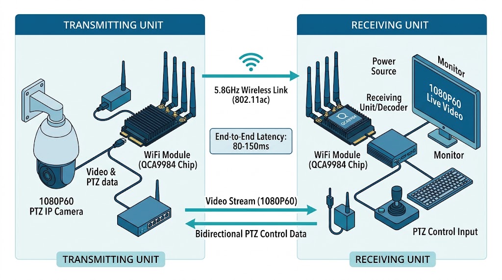
Figure 2: Fixed-site line-of-sight surveillance – WiFi-IP video transmission architecture
✅ Recommended Solution: Develop WiFi-IP video transmission with Zukaka WiFi5/6 modules, optimal cost-effectiveness
5GHz Band Solution (5725~5850MHz ISM / U-NII, globally applicable)
- Band: 5725~5850MHz ISM license-exempt; 5.15~5.35GHz outdoor engineering requires DFS radar detection in most regions
- Effective line-of-sight distance: 0~3km (directional antenna, depending on deployment environment attenuation)
- End-product EIRP limit (by sales region regulation): China ≤30dBm, FCC ≤36dBm, CE ≤25dBm (ETSI EN 301 893)
- Performance: 1080P60, end-to-end latency 80~140ms, jitter <15ms
- Certification: SRRC (WLAN) / FCC Part15 / CE-RED + RoHS (selected by sales region)
6GHz Band Solution (5925~7125MHz, 802.11ax WiFi 6E, partially opened in some regions)
- Band: 5925~7125MHz, richer bandwidth resources and less co-channel interference; mainland China has not yet opened 6GHz unlicensed use—verify local spectrum policy before deployment
- Effective line-of-sight distance: 0~3km (directional antenna)
- End-product EIRP limit: FCC standard power ≤36dBm / low power ≤14dBm; CE ≤23dBm (ETSI EN 303 687)
- Performance: 1080P60, end-to-end latency 80~140ms
- Certification: FCC Part15 Subpart E, CE-RED (not applicable in China currently)
Applicable Services: IPC HD video backhaul + PTZ control and bidirectional IP data transmission; environmental requirements include outdoor IP65 protection, wide temperature range -40°C to +65°C, lightning protection.
The Zukaka module solution is recommended for this scenario; stability is excellent without occlusion, supporting point-to-point and point-to-multipoint aggregation networking.
Scenario 2: Fixed-Site NLOS Urban Surveillance (Between Buildings, Wall/Tree Occlusion)
🏗️ System Architecture Description
Scenario Positioning: In dense urban building areas, buildings, trees, and other occlusions exist between transmitter and receiver, preventing WiFi direct links from penetrating. Solutions with stronger multipath resistance such as COFDM or 1.4G MESH self-organizing networks are required.
System Composition: Front-end camera/IPC → COFDM transmitter (private modulation) → NLOS wireless link (diffraction/multipath) → COFDM receiver → surveillance center; in multi-node scenarios, 1.4G MESH relay nodes perform multi-hop forwarding.
Key Technical Points: ① COFDM uses OFDM subcarrier modulation with multipath fading resistance far exceeding WiFi; ② 1.4G band has longer wavelength, with penetration and diffraction advantages over 5.8G; ③ MESH self-organizing networks support multi-hop relays, bypassing obstructing buildings without manual route configuration.
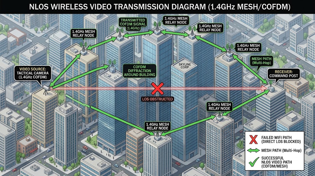
Figure 3: Urban NLOS surveillance – COFDM/MESH architecture
✅ Recommended Solution: COFDM private protocol video transmission / 1.4G MESH self-organizing network, WiFi technical route (IP video transmission) not recommended as the main link
5GHz Band Solution (5725~5850MHz)
- NLOS effective distance: 0~1000m (diffraction-limited, the denser the occlusion the shorter the distance; higher in regions with higher EIRP limits)
- End-product EIRP limit (by sales region regulation): China ≤30dBm, FCC ≤36dBm, CE ≤25dBm
- Bandwidth: 5/10/20MHz configurable
- Receive sensitivity: ≤-94dBm@10MHz
- Latency: 60~120ms, 1080P30/60
- Certification: SRRC (wireless video transmission equipment, non-WLAN) / FCC / CE-RED + RoHS (selected by sales region)
1.4GHz Band Solution (1427~1525MHz, strong penetration/diffraction)
- NLOS effective distance: 0~1.5km (1.4G long wavelength, penetration and diffraction advantages over 5.8G, suitable for multi-occlusion networking)
- End-product EIRP limit (by sales region regulation): China ≤30dBm, FCC ≤36dBm, CE ≤25dBm
- Bandwidth: 5/10/20MHz configurable
- Receive sensitivity: ≤-94dBm@10MHz
- Latency: 60~120ms, 1080P30/60
- Certification: SRRC / FCC / CE-RED (1.4G band use requires verification of local spectrum authorization)
Note: WiFi has weak diffraction capability and is prone to frequent packet loss and stalling in building occlusion environments, so WiFi module IP video transmission is not recommended as an NLOS main link; COFDM has stronger multipath resistance but higher cost and does not natively support general Layer 2 IP networking. For urban NLOS multi-node networking scenarios, Zukaka 1.4G MESH self-organizing network equipment can be selected, such as YNW-6502SW (outdoor broadband MESH base station, 70Mbps, 10+km) and YNW-6502BK (emergency video surveillance MESH ball camera, 30× PTZ), leveraging 1.4G’s strong penetration to achieve multi-hop self-organizing networking under NLOS conditions.
Scenario 3: Vehicular Mobile Video Transmission (Inspection Vehicle, Emergency Command Vehicle, Speed 30~100km/h)
🏗️ System Architecture Description
Scenario Positioning: Mobile carriers (inspection vehicles, emergency command vehicles) backhaul real-time vehicular camera footage while driving, requiring compensation for Doppler frequency shift and multipath fading caused by high-speed mobility to ensure uninterrupted video links.
System Composition: Vehicular camera → vehicular COFDM/MESH radio (roof antenna) → vehicle-to-ground/vehicle-to-vehicle wireless link → ground base station or other vehicles → command center; ultra-long-range scenarios switch to 4G/5G public network for recording backhaul.
Key Technical Points: ① Must support Doppler frequency shift compensation to counteract carrier frequency offset caused by high-speed mobility; ② COFDM resists multipath fading, adapting to urban reflection environments; ③ 1.4G MESH supports vehicle-to-vehicle and vehicle-to-ground multi-hop self-organizing networking, with vehicles auto-networking in convoy formation.
Divided into two solutions: short-range vehicle-to-ground line-of-sight link and wide-area remote public network transmission
3.1 Short-Range Vehicle-to-Ground Base Station (Mobile Line-of-Sight)

Figure 4: Vehicular mobile video transmission – COFDM/MESH architecture
✅ Recommended Solution: COFDM private video transmission / vehicular MESH self-organizing network, WiFi module IP video transmission solution not recommended
- 5GHz Band Solution (5725~5850MHz): Distance 0~2km (mobile line-of-sight, affected by EIRP limits); bandwidth 10/20MHz; receive sensitivity ≤-92dBm; latency 70~130ms; 1080P30.
- 1.4GHz Band Solution: Distance 0~2km (stronger diffraction, suitable for convoy formation occlusion scenarios); bandwidth 10/20MHz; receive sensitivity ≤-92dBm; latency 70~130ms.
- Complete Device EIRP Limit (by sales region regulation): China ≤30dBm, FCC ≤36dBm, CE ≤25dBm.
- Certification: SRRC (wireless video transmission equipment) / FCC / CE-RED + RoHS (selected by sales region).
The vehicular MESH self-organizing network solution can use Zukaka 1.4G MESH vehicular radios, such as YNW-6410CZ (vehicular MESH, 10W, 80Mbps, 20~60km) and YNW-6508CZ (vehicular broadband MESH), supporting vehicle-to-vehicle and vehicle-to-ground multi-hop self-organizing networking, suitable for high-speed mobility Doppler scenarios.
Core Requirements: Support Doppler frequency shift compensation, resist multipath fading; WiFi solutions are affected by Doppler effect and prone to video dropout during high-speed mobility.
3.2 Wide-Area Remote Vehicular (No Line-of-Sight Link)
Uses 4G/5G public network video transmission with no distance limit; latency 200~1000ms (fluctuates with carrier network quality), suitable for recording backhaul, not for real-time control.
Scenario 4: Airborne UAV Video Transmission (Inspection, FPV)
🏗️ System Architecture Description
Scenario Positioning: UAVs backhaul aerial footage to ground stations in real-time during flight, while ground stations downlink flight control/gimbal commands to the UAV. Two technical routes exist: high-speed long-range (COFDM) and low-speed short-range (WiFi-IP).
System Composition: UAV onboard camera + video transmission transmitter → downlink wireless video link → ground station receiver + display; ground station remote controller → uplink control link → UAV flight control. Ultra-long-range scenarios switch to 4G/5G public network for recording backhaul.
Remote Controller→Uplink Control→Flight Control
Key Technical Points: ① High-speed flight requires COFDM with Doppler compensation, latency 30~60ms; ② WiFi is only suitable for ≤1km low-speed short-range, latency 90~150ms; ③ Antenna swing and attitude changes cause signal fluctuation, requiring antenna diversity and adaptive bitrate.
4.1 Mid-Short-Range UAV Line-of-Sight Scenario
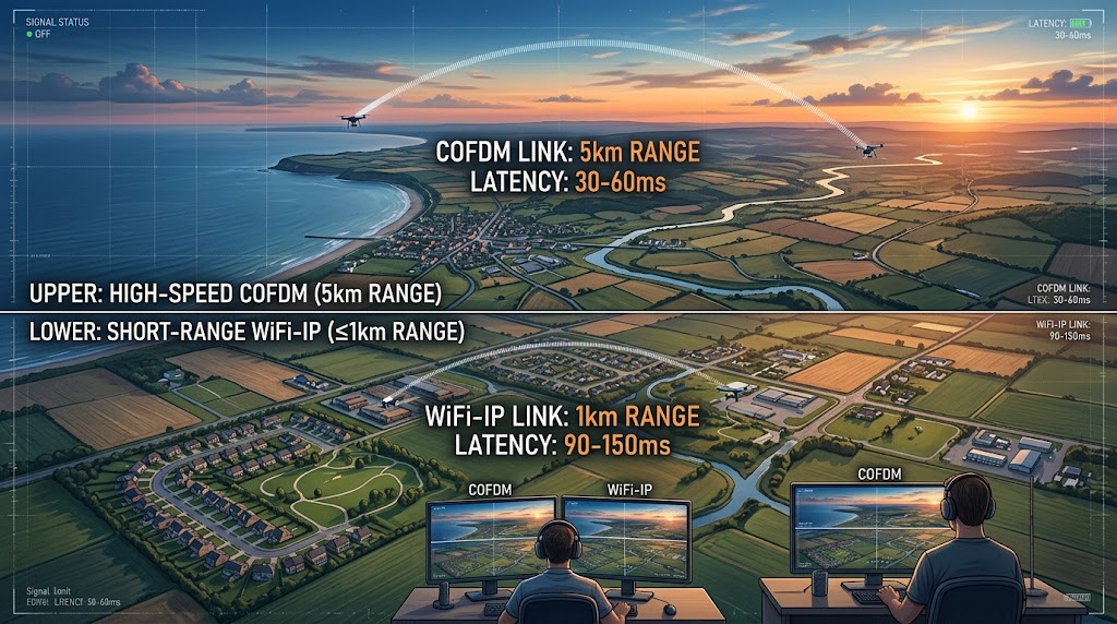
Figure 5: Airborne UAV video transmission – COFDM vs WiFi dual-solution comparison
Solution A: COFDM Private Video Transmission (Preferred, High-Speed Flight)
- Band: 5725~5850MHz (5.8G ISM)
- Effective distance: 0~7km (line-of-sight, affected by EIRP limits, higher in high-limit regions)
- End-product EIRP limit (by sales region regulation): China ≤30dBm, FCC ≤36dBm, CE ≤25dBm
- Bandwidth: 10/20MHz; receive sensitivity ≤-91dBm
- Latency: 30~60ms, 1080P60
- Certification: SRRC (wireless video transmission equipment) / FCC / CE-RED (selected by sales region)
Solution B: Zukaka WiFi Module IP Video Transmission (Only suitable for low-speed short-range ≤1km UAVs)
- Band: 5725~5850MHz (5.8G ISM); 6GHz (5925~7125MHz, not yet opened in China) optional in some regions
- Effective distance: ≤1.2km line-of-sight
- End-product EIRP limit (by sales region regulation): China ≤30dBm, FCC ≤36dBm, CE ≤25dBm; 6GHz tiered by FCC sub-band
- Receive sensitivity: ≤-67dBm (5GHz @80M MCS9)
- Latency: 90~150ms
- Certification: SRRC (WLAN) / FCC Part15 / CE-RED (selected by sales region)
Limitations: High-speed flight and antenna swing cause Doppler effects, prone to packet loss, not suitable for long-range high-speed inspection UAVs.
4.2 Ultra-Long-Range UAV (>5km without line-of-sight)
4G/5G public network video transmission, latency 200ms~1s, suitable only for recording backhaul, not for real-time video monitoring control.
V. Selection Red Lines Summary
1. High-speed mobility scenarios (vehicular, long-range high-speed UAVs): IP video transmission solutions developed with WiFi modules are not recommended; Doppler effect causes frequent link drops. COFDM or 1.4G MESH self-organizing network equipment (such as Zukaka MESH product line) is recommended for such scenarios;
2. NLOS occlusion scenarios: WiFi diffraction is insufficient—do not force WiFi solutions, as project acceptance failure risk is high;
3. EIRP is an end-product parameter, not module port output power. The higher the antenna gain, the lower the allowed module transmit power—both domestic and foreign regulations have mandatory limits;
4. Module SRRC certificate cannot replace end-product SRRC: baseboard, power supply, and antenna change end-product RF parameters—end products must be independently tested before market launch;
5. Product delivery must distinguish product definitions: bridge firmware can only be delivered as a wireless bridge; if delivered as wireless IP video transmission, it must be accompanied by a video-specific test report, otherwise bidding will be classified as a product category mismatch.
VII. FAQ
What is the difference between a wireless bridge and a wireless video transmission device?
Can a WiFi module be used for wireless video transmission?
How to choose between 5.8G WiFi video transmission and COFDM video transmission?
What is the typical end-to-end latency of WiFi-IP video transmission?
What certifications are required to bring a wireless video transmission device to market?
Should UAV video transmission use WiFi or COFDM?
What scenarios are 1.4G MESH self-organizing networks suitable for?
Can a module’s SRRC certificate replace the end-product SRRC?
VI. Conclusion
Many integrators and equipment manufacturers easily confuse wireless bridges with wireless video transmission devices. With zukaka.com industrial-grade Qualcomm WiFi modules (e.g., QCA9984), developers can rapidly develop mature and stable industrial wireless bridges, or combine them with codec hardware and custom low-latency firmware to build cost-effective WiFi-IP video transmission devices perfectly suited for fixed line-of-sight industrial surveillance projects. For NLOS occlusion and vehicular/UAV high-speed mobility scenarios, COFDM video transmission is recommended as an alternative. In the project planning phase, the optimal selection among wireless bridges, IP video transmission, and COFDM video transmission can be made based on occlusion, mobility, transmission distance, and domestic/foreign compliance requirements.
— This article is compiled based on Zukaka Qualcomm WiFi module product features, for technical selection reference only —


