Wireless AP Antenna Design Guide for Optimal Performance
Blog 2026-06-01
Wireless AP Antenna Design Guide for Optimal Performance
Key Overview
Core Issue: How to select and design antennas for wireless APs that balance performance, cost, and form factor constraints.
Key Conclusions: Antenna selection must align with product positioning—home APs prioritize cost and integration, enterprise APs require higher gain and diversity. Proper antenna matching, placement, and isolation are critical. Testing and validation are essential before mass production.
Antennas are the critical interface between the wireless AP and its environment—they determine signal coverage, data rate, and overall user experience. A well-designed antenna system can make the difference between a mediocre AP and an excellent one. However, antenna design involves complex trade-offs between performance, cost, size, and regulatory compliance. As a core component of how to balance RF performance and cost in wireless AP motherboard development, antenna design requires careful consideration at every stage. Why is antenna design so critical? What types of antennas are commonly used? How do you select the right antenna for your application? What are the key integration challenges? This article provides comprehensive guidance.
Why Antenna Design is Critical for Wireless Performance
Antenna design fundamentally impacts wireless performance:
- Coverage range and signal strength: Antenna gain directly determines how far signals can reach. Higher gain antennas extend coverage but may reduce omnidirectionality.
- Data rate and throughput: Antenna efficiency and diversity affect signal quality, which determines achievable data rates—especially in challenging environments.
- User experience: Poor antenna design leads to dead zones, dropped connections, and inconsistent performance that users immediately notice.
- Regulatory compliance: Antenna design impacts radiated emissions and must comply with FCC, CE, and other regional requirements. See EMC certification guide for details.
Types of Antennas Used in Wireless APs
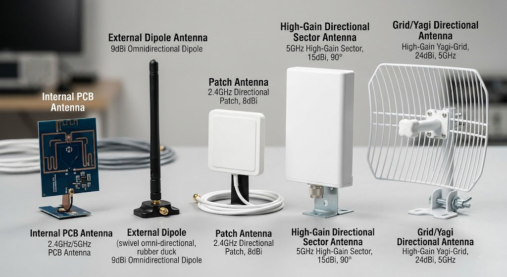
Common antenna types used in wireless APs:
| Antenna Type | Typical Gain | Pattern | Cost | Best For |
|---|---|---|---|---|
| Internal PCB Antenna | 0-3 dBi | Omnidirectional | Low | Home APs, compact designs |
| Chip Antenna | 1-4 dBi | Omnidirectional | Low-Medium | Portable devices, small form factors |
| Rubber Duck Dipole | 2-5 dBi | Omnidirectional | Low-Medium | Consumer APs, routers |
| Patch Antenna | 5-10 dBi | Directional | Medium | Enterprise APs, outdoor use |
| Panel Antenna | 8-15 dBi | Highly Directional | Medium-High | Outdoor, long-range applications |
| Omni Antenna | 3-8 dBi | Omnidirectional | Medium | Enterprise ceiling APs |
Each antenna type has advantages and disadvantages. For more on hardware design differences between product types, see home vs enterprise AP comparison.
Key Antenna Specifications and Metrics
Key antenna specifications to consider:
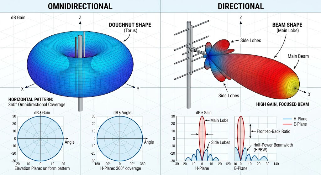
- Gain: Measure of antenna’s ability to focus radiation in a particular direction (dBi). Higher gain = more directional.
- Radiation Pattern: Visual representation of how the antenna radiates energy in 3D space. Omnidirectional vs directional.
- VSWR (Voltage Standing Wave Ratio): Measure of impedance matching. Ideal value is 1:1; values > 2:1 indicate poor matching.
- Return Loss: Measure of power reflected back to source. Values < -10dB indicate good matching.
- Efficiency: Ratio of radiated power to input power. High efficiency = better performance.
- Polarization: Orientation of the electromagnetic wave (vertical, horizontal, circular).
- Frequency Band: Range of frequencies the antenna is designed to operate in (2.4GHz, 5GHz, 6GHz).
| Specification | Definition | Target Value |
|---|---|---|
| Gain | Directional radiation efficiency | 2-6 dBi (consumer), 6-12 dBi (enterprise) |
| VSWR | Impedance matching quality | < 1.5:1 ideal, < 2:1 acceptable |
| Return Loss | Power reflection | < -15dB ideal, < -10dB acceptable |
| Efficiency | Radiated power ratio | > 70% ideal |
| Bandwidth | Frequency coverage | 2.4-2.5GHz, 5.15-5.85GHz |
How to Select the Right Antenna for Your AP
Steps to select the right antenna:
- Define requirements: Determine coverage area, data rate targets, and environmental constraints (indoor vs outdoor).
- Select antenna type: Choose based on gain requirements and form factor (internal vs external).
- Consider MIMO requirements: Number of streams (2×2, 4×4) affects antenna count and placement.
- Evaluate cost vs performance trade-offs: Higher gain often means higher cost and larger size.
- Verify regulatory compliance: Ensure antenna meets FCC/CE radiation requirements.
| Product Type | Recommended Antenna Type | Typical Gain | Number of Antennas |
|---|---|---|---|
| Home AP | Internal PCB or chip antenna | 2-3 dBi | 2-4 (2×2 MIMO) |
| SOHO AP | Rubber duck or internal antenna | 3-5 dBi | 2-4 |
| Enterprise AP | External omni or patch antenna | 5-8 dBi | 4-8 (4×4 MIMO) |
| Outdoor AP | High-gain directional antenna | 8-15 dBi | 2-4 |
Antenna Integration and Placement Considerations
Key integration considerations:
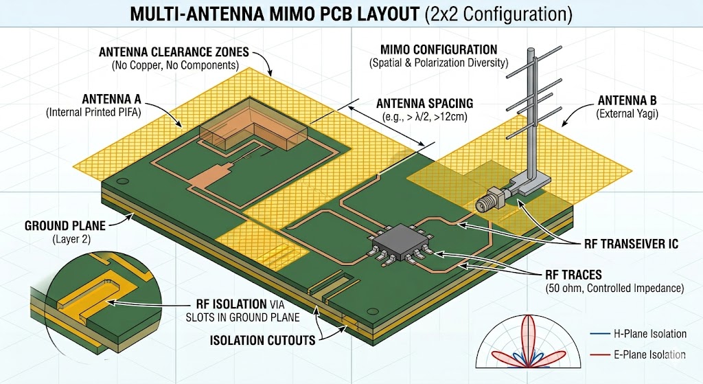
- Antenna placement relative to metal components: Keep antennas away from metal chassis, shields, and heat sinks to avoid detuning and pattern distortion.
- Ground plane design: Provide adequate ground plane under antennas but maintain clearance zones to prevent shorting.
- Antenna-to-antenna isolation (MIMO): Maintain sufficient distance between antennas (typically ≥ λ/4) to ensure good diversity and minimize mutual coupling.
- Cable and connector selection: Use high-quality RF cables with low loss; minimize cable length to reduce signal attenuation.
- Environmental factors: Consider enclosure materials (dielectric constant), mounting location, and user interaction.
Impedance Matching and Tuning
Impedance matching is critical for antenna performance:
- Why matching matters: Antennas are typically designed for 50Ω impedance. Mismatched impedances cause signal reflection and power loss.
- Matching network design: Use LC networks or π-networks to match antenna impedance to 50Ω. Consider both 2.4GHz and 5GHz bands.
- Tuning process: Use vector network analyzer (VNA) to measure S-parameters and adjust component values for optimal matching.
- Consider environmental effects: Antenna impedance changes with proximity to objects—tune with the actual enclosure and mounting conditions.
| Impedance Matching Parameter | Acceptable Range | Impact of Poor Matching |
|---|---|---|
| VSWR | < 1.5:1 | Power loss, reduced range |
| Return Loss | < -15dB | Signal reflection, inefficient power transfer |
| Matching Bandwidth | Covers entire operating band | Frequency-dependent performance issues |
Antenna Testing and Validation
Essential antenna tests:
- VSWR/Return Loss Measurement: Use VNA to verify impedance matching across operating frequencies.
- Radiation Pattern Measurement: Use anechoic chamber to measure far-field radiation patterns.
- Gain and Efficiency Measurement: Determine actual antenna gain and radiation efficiency.
- OTA (Over-the-Air) Testing: Measure real-world performance including throughput, range, and coverage.
- Environmental Testing: Test performance under different conditions (temperature, humidity, enclosure effects).
Common Antenna Design Issues and Solutions
Common issues and solutions:
| Issue | Cause | Solution |
|---|---|---|
| Low Gain/Range | Poor antenna efficiency, detuning | Optimize ground plane, improve matching, relocate antenna |
| High VSWR | Impedance mismatch | Redesign matching network, adjust component values |
| Poor MIMO Performance | Insufficient antenna isolation | Increase antenna separation, use orthogonal polarization |
| Pattern Distortion | Metal interference, improper placement | Relocate antenna away from metal components |
| Regulatory Failures | Excessive radiated emissions | Add filtering, improve shielding, optimize antenna placement |
Summary
Antenna design requires careful consideration of multiple factors:
- Antenna selection must align with product positioning: Home APs prioritize cost and integration; enterprise APs require higher gain and diversity.
- Proper placement and isolation are critical: Keep antennas away from metal, maintain adequate separation for MIMO.
- Impedance matching ensures maximum power transfer: Invest time in matching network design and tuning.
- Thorough testing is essential before mass production: Test in final enclosure, verify performance across all operating conditions.
As a core component of how to balance RF performance and cost in wireless AP motherboard development, antenna design must be coordinated with PCB layout, RF front-end selection, and EMC certification to achieve optimal system performance.
References
Frequently Asked Questions
Q: What’s the difference between internal and external antennas for wireless APs?
Internal antennas (PCB or chip antennas) are integrated into the device, offering lower cost and cleaner aesthetics but typically lower gain (2-4 dBi). External antennas (rubber duck, patch, omni) provide higher gain (5-12 dBi) and better performance but add cost and require external mounting. Home APs often use internal antennas, while enterprise APs typically use external antennas for better coverage and flexibility.
Q: How many antennas do I need for MIMO?
The number of antennas depends on the MIMO configuration: 2×2 MIMO requires 2 antennas, 4×4 MIMO requires 4 antennas, and so on. For optimal performance, antennas should be separated by at least 0.5 wavelengths (≈ 6cm at 2.4GHz, ≈ 3cm at 5GHz) and use orthogonal polarization when possible. Proper isolation between antennas is critical for good MIMO performance.
Q: What causes antenna detuning and how can it be prevented?
Antenna detuning occurs when the antenna’s resonant frequency shifts due to environmental factors like nearby metal objects, enclosure materials, or user proximity. Prevention strategies include: maintaining adequate clearance zones around antennas, using proper ground plane design, testing with the final enclosure, and implementing adjustable matching networks that can compensate for environmental effects.


