EMC Certification Guide for Wireless AP Motherboards
Key Overview
Core Issue: How to design wireless AP motherboards that meet EMC compliance requirements and avoid costly redesigns.
Key Conclusions: EMC compliance must be considered from the earliest design stages. Proper grounding, shielding, filtering, and layout are essential. Pre-compliance testing significantly reduces certification costs and delays.
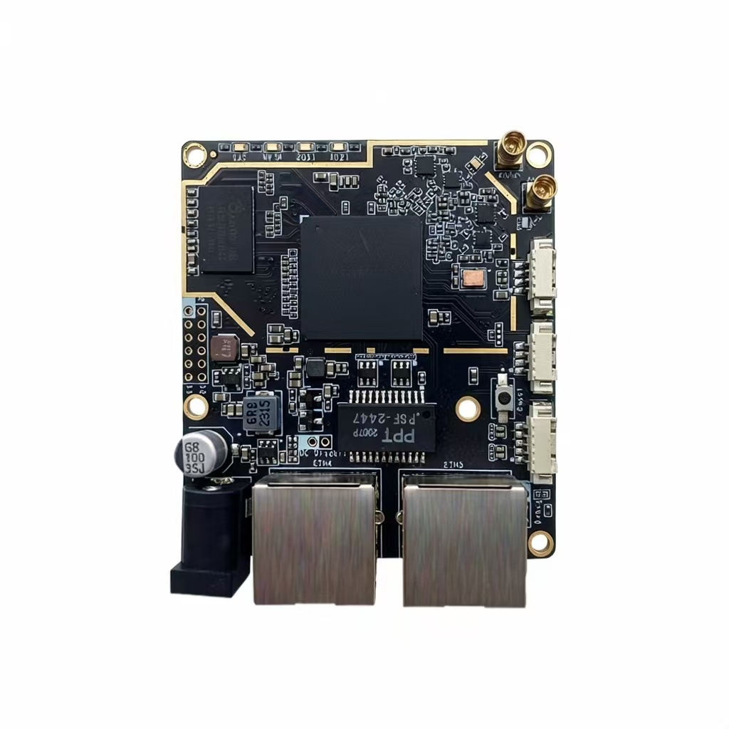
EMC (Electromagnetic Compatibility) certification is essential for wireless AP products to be legally sold in most markets. Poor EMC design not only leads to certification failures but can also cause interference with other devices and poor user experience. As a core component of how to balance RF performance and cost in wireless AP motherboard development, EMC compliance must be considered from the earliest design stages. Why is EMC certification important? What standards apply? How can you design for compliance? This article provides comprehensive guidance.
Why EMC Certification Matters
EMC certification is critical for several reasons:
- Legal requirement: Most countries require EMC certification before products can be sold.
- Market access: Without certification, products cannot be sold in major markets like the EU, US, and Asia.
- Product reliability: Good EMC design ensures the product operates reliably in real-world environments with other electronic devices.
- Brand reputation: Products with poor EMC performance may cause interference complaints and damage brand reputation.
- Cost savings: Designing for EMC from the start avoids costly redesigns and certification retests.
Key EMC Standards and Regulations
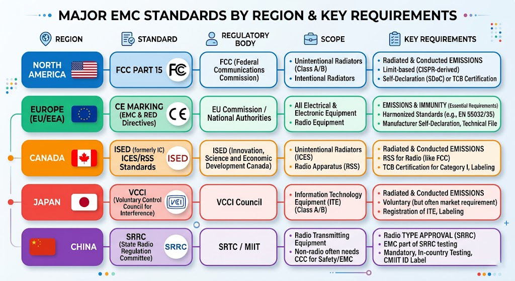
Key EMC standards for wireless APs:
| Region | Emissions Standard | Immunity Standard | Specific Requirements |
|---|---|---|---|
| US (FCC) | Part 15 Subpart B | Part 15 Subpart B | Part 15.247 for intentional radiators |
| EU (CE) | EN 301 489-1/-17 | EN 301 489-1/-17 | EN 55032, EN 55035 |
| Canada (IC) | ICES-003 | ICES-003 | Similar to FCC Part 15 |
| Japan (VCCI) | VCCI Class B | VCCI Class B | Based on CISPR standards |
| China (SRRC) | GB 8702 | GB/T 17626 | Additional local requirements |
EMC Design Considerations for Wireless APs
Key EMC design principles:
- Minimize radiating loops: Keep high-current loops small to reduce radiation.
- Provide proper grounding: Single-point grounding, adequate ground planes.
- Use shielding where necessary: Metal enclosures, shielded cables.
- Implement proper filtering: Power line filters, signal line filters.
- Control signal integrity: Impedance matching, termination.
- Separate analog and digital circuits: Prevent digital noise from affecting analog/RF circuits.
Grounding and Shielding Techniques
Grounding and shielding techniques:
- Single-point grounding: Connect all ground points to a single reference point to avoid ground loops.
- Ground plane design: Use solid ground planes for low impedance and effective shielding.
- RF ground vs digital ground: Separate grounds with single-point connection.
- Shielding enclosures: Use metal enclosures or conductive coatings for sensitive circuits.
- Shielded cables: Use shielded cables for external connections.
- EMI gaskets: Ensure proper sealing of enclosure seams with conductive gaskets.
Power and Signal Filtering
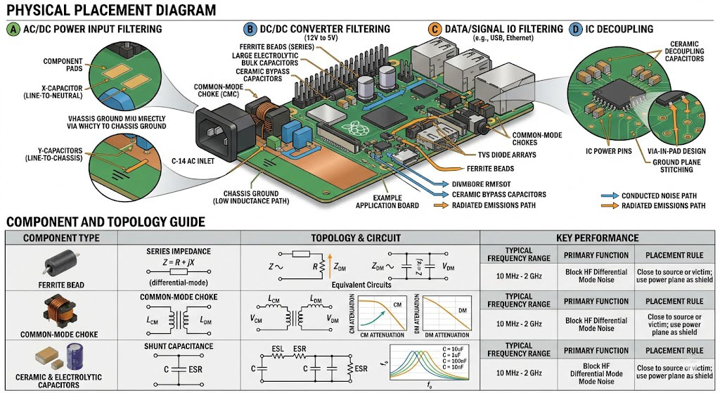
Filtering techniques:
- Power supply filtering: Use EMI filters on AC/DC inputs to prevent conducted emissions.
- DC-DC converter filtering: Add LC filters on DC-DC outputs to reduce switching noise.
- Signal line filtering: Use ferrite beads and capacitors on signal lines.
- RF filtering: Use band-pass filters to prevent out-of-band emissions.
- ESD protection: Add ESD diodes to protect sensitive inputs/outputs.
| Filter Type | Application | Key Components |
|---|---|---|
| Power Line Filter | AC/DC input | Common-mode chokes, X/Y capacitors |
| Signal Filter | Data lines | Ferrite beads, RC networks |
| RF Filter | RF inputs/outputs | SAW filters, LC filters |
| DC-DC Filter | Switching regulator outputs | LC low-pass filters |
PCB Layout for EMC
PCB layout best practices for EMC:
- Separate noisy and sensitive circuits: Place DC-DC converters away from RF circuits.
- Minimize trace lengths: Short traces reduce radiation and improve signal integrity.
- Use ground planes: Provide continuous ground planes for return paths.
- Route sensitive signals over ground planes: Keep high-speed and RF signals over ground.
- Use differential pairs for high-speed signals: Differential signaling reduces EMI.
- Place decoupling capacitors close to IC power pins: Minimize power supply noise.
- Use guard traces for sensitive signals: Ground guard traces around sensitive lines.
Pre-Compliance Testing
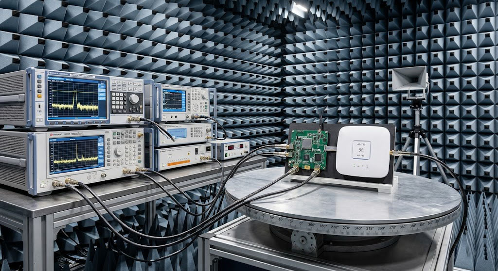
Pre-compliance testing steps:
- Set up test environment: Use a semi-anechoic chamber or open area test site.
- Conduct radiated emissions test: Measure emissions across the frequency spectrum.
- Conduct conducted emissions test: Measure noise on power lines.
- Perform immunity tests: Test ESD, EFT, and surge immunity.
- Analyze results: Identify problem areas and implement fixes.
- Retest: Verify fixes before formal certification.
Certification Process
Typical certification process:
- Determine applicable standards: Identify which standards apply to your product and markets.
- Prepare documentation: Create technical documentation, test reports, and user manuals.
- Select a testing laboratory: Choose an accredited lab for testing.
- Submit product for testing: Send samples to the lab for formal testing.
- Address failures: Fix any issues identified during testing.
- Obtain certification: Receive certification documents and place marking on products.
Common EMC Issues and Solutions
Common EMC issues and solutions:
| Issue | Cause | Solution |
|---|---|---|
| Excessive Radiated Emissions | Poor grounding, long traces, unfiltered signals | Improve grounding, add shielding, implement filtering |
| Conducted Emissions Failures | Insufficient power filtering | Add EMI filter, improve grounding |
| ESD Failures | Lack of ESD protection | Add ESD diodes, implement proper grounding |
| EMI Immunity Failures | Poor shielding, insufficient filtering | Add shielding, improve filtering |
| Clock Radiation | Unshielded clock traces | Route clocks over ground, use differential signaling |
Summary
EMC certification requires careful planning and design:
- EMC must be designed into the product from the start: Don’t treat it as an afterthought.
- Understand applicable standards: Different markets have different requirements.
- Implement proper grounding and shielding: These are foundational to EMC performance.
- Use effective filtering: Power, signal, and RF filtering are essential.
- Follow PCB layout best practices: Layout significantly impacts EMC performance.
- Conduct pre-compliance testing: Identify and fix issues before formal certification.
As a core component of how to balance RF performance and cost in wireless AP motherboard development, EMC design must be coordinated with PCB layout, antenna design, and RF front-end selection to achieve optimal system performance.
References
Frequently Asked Questions
Q: What’s the difference between EMI and EMS?
EMI (Electromagnetic Interference) refers to the emissions from a device that may interfere with other devices. EMS (Electromagnetic Susceptibility) refers to a device’s ability to operate correctly in the presence of electromagnetic interference from other sources. EMC certification tests both: ensuring the device doesn’t emit excessive EMI and that it can withstand reasonable EMS levels.
Q: How much does EMC certification cost?
Costs vary depending on the product complexity, number of standards, and testing laboratory. Typical costs range from $5,000 to $20,000 for wireless APs. However, the cost of fixing failures and retesting can add significantly to this amount. Investing in pre-compliance testing can reduce overall costs.
Q: How long does EMC certification take?
The certification process typically takes 2-8 weeks depending on testing complexity and whether fixes are needed. If the product passes all tests on the first attempt, it can be as quick as 2 weeks. However, if redesigns are required, it can take several months. Planning for EMC from the start significantly reduces this timeline.