Does a Metal Enclosure Affect Wireless AP RF Performance? Mechanical-Electrical Co-Design Guide
Blog 2026-06-01
Does a Metal Enclosure Affect Wireless AP RF Performance? Mechanical-Electrical Co-Design Guide
Key Overview
Core Issue: Metal enclosures reflect electromagnetic waves, shift antenna impedance, and reduce radiation efficiency. Understanding these mechanisms and applying proper co-design principles is essential for maintaining RF performance in real products.
Key Conclusions: Mechanical design directly determines wireless AP RF performance. Metal enclosures reflect signals and require antenna windows or external antennas. Plastic enclosures transmit RF well but offer less EMI shielding. Maintain at least 5-10mm clearance between metal structures and antennas. Aperture location controls radiation direction. Co-design from day one eliminates expensive late-stage fixes.
Many wireless AP projects perform well at the board level, but once the product is assembled into its enclosure, performance starts to fluctuate. The root cause is usually not the chipset — it’s the mechanical design. The metal enclosure, aperture positions, and antenna clearance all significantly affect the final wireless performance. That’s why structural and RF design must move forward together from day one.
This article covers exactly why mechanical design affects RF, how metal enclosures change antenna behavior, the real differences between plastic and metal enclosures, minimum clearance rules, aperture and shielding effects, co-design workflows, common interference patterns, and how to balance industrial design with radio performance.
Why Mechanical Design Affects Wireless Performance
Mechanical design impacts wireless performance through five main mechanisms:
- Enclosure material changes wave propagation: Metal reflects electromagnetic waves. Plastic transmits them. The material choice sets a hard bound on how much RF energy can leave the product.
- Structure-to-antenna distance shifts impedance: When metal structures get too close to the antenna, the impedance changes. The matching network designed for free-space conditions no longer works.
- Aperture location controls radiation direction: The openings in the enclosure act like waveguide apertures. Where you cut holes determines where the signal goes.
- Internal routing and shielding affect noise floor: Metal brackets, screw posts, and heat sinks near the antenna can couple noise into the RF section, raising the noise floor by 3-5dB in severe cases.
- Asynchronous design causes unpredictable performance: If the mechanical team finishes the enclosure before the RF team reviews it, the resulting performance is a gamble. Fixing it later requires tooling changes that cost $5,000-15,000 per mold modification.
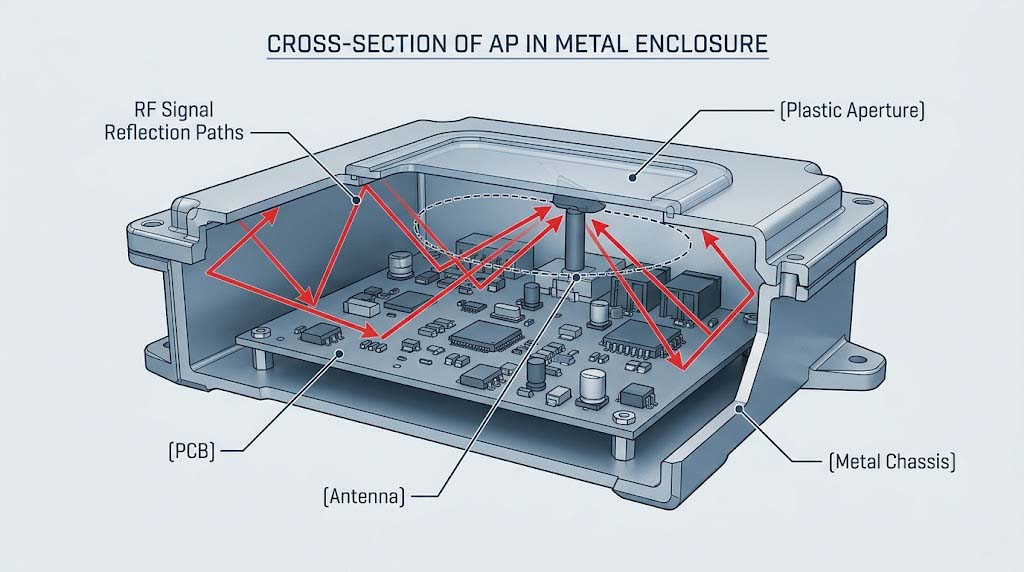
How Metal Enclosures Affect Antennas
A metal enclosure interacts with the antenna in five distinct ways:
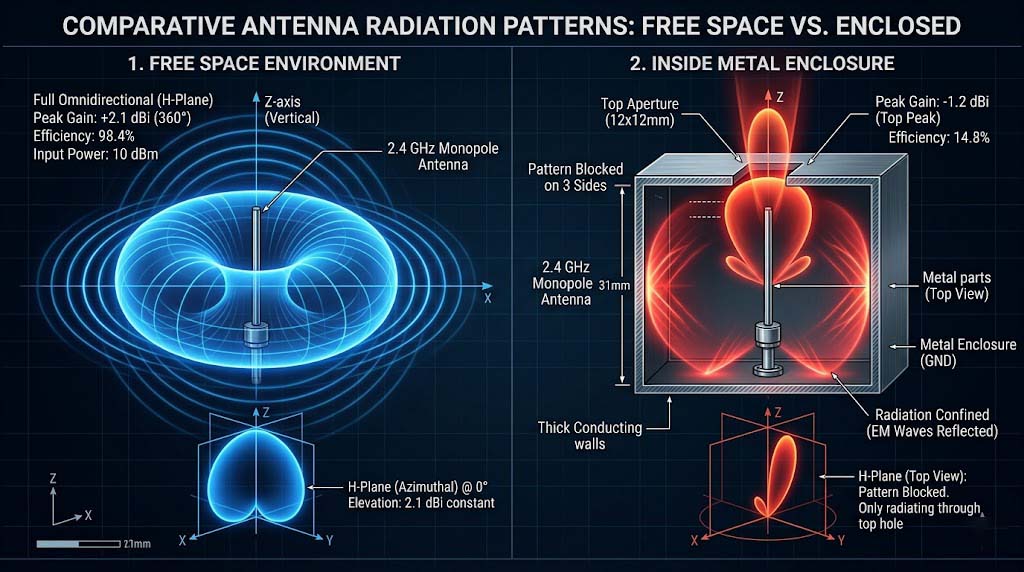
- Reflects electromagnetic waves: The conductive surface acts as a reflector, changing the radiation pattern from omnidirectional to directional. Gain in the direction opposite the metal can drop by 6-10dB.
- Shifts antenna impedance: Proximity to metal changes the antenna’s self-impedance. A 50Ω design can drift to 35Ω or 70Ω, causing mismatch loss of 1-3dB.
- Reduces radiation efficiency: Power that couples into the enclosure surface turns into ohmic loss instead of radiated signal. Efficiency can drop from 70% to 30-40% in poorly designed layouts.
- Creates eddy currents: RF currents induce circulating currents on the metal surface, generating I2R losses and heat.
- Degrades VSWR: Standing wave ratio typically worsens from 1.5:1 (free space) to 2.5:1 or higher when metal is within λ/10 of the antenna.
Quantified Impact of Metal Enclosure on Antenna Parameters
| Parameter | Free Space (Reference) | Metal Enclosure Within 5mm | Metal Enclosure Within 20mm |
|---|---|---|---|
| Antenna Gain | 3.0 dBi | -1.5 to 0.5 dBi | 1.5 to 2.5 dBi |
| Radiation Efficiency | 70-80% | 20-40% | 50-65% |
| VSWR | 1.3:1 – 1.5:1 | 2.0:1 – 3.5:1 | 1.6:1 – 2.0:1 |
| Impedance | 50 Ω | 25-40 Ω | 40-55 Ω |
| Resonant Frequency Shift | 0 MHz | -40 to -80 MHz | -10 to -25 MHz |
| Typical Range Impact | Baseline | -40% to -60% | -10% to -25% |
Plastic vs Metal Enclosures: RF Trade-Offs
The enclosure material decision is one of the first and most consequential choices in a wireless AP project. Here is how the two options compare across the dimensions that matter:
Plastic vs Metal Enclosure Comparison
| Dimension | Plastic (ABS/PC) | Metal (Aluminum/Steel) |
|---|---|---|
| RF Transparency | High. Signals pass through with 0.5-1.5dB loss depending on wall thickness and material grade | Near-zero. Metal reflects >95% of incident RF energy. Signals cannot escape without intentional openings |
| Antenna Strategy | Internal PCB antennas, chip antennas, or stamped metal work well. No special windows needed | Requires external antennas, plastic antenna windows, or slot antennas integrated into the metal surface |
| EMI Shielding | Poor. Plastics offer no inherent EMI shielding. Requires conductive coating, metal foil lining, or internal shield cans | Excellent. Metal enclosure acts as a natural Faraday cage. Typical shielding effectiveness: 40-60dB at 2.4GHz |
| Thermal Conductivity | Low: 0.2-0.4 W/mK (ABS). Requires thermal vias, heat sinks, or active cooling for high-power designs | High: 150-200 W/mK (aluminum). Serves as a heat spreader, reducing internal hot spot temperatures by 10-15℃ vs plastic |
| Structural Strength | Moderate. Requires ribs and gussets for rigidity. Can deform under prolonged heat or UV exposure | High. Withstands shock, vibration, and environmental stress. Suitable for outdoor and industrial installations |
| Industrial Design | Flexible shapes, colors, textures. Lower tooling cost ($15,000-40,000 per mold) | Premium look and feel, tighter tolerances. Higher tooling cost ($30,000-80,000 per mold) |
| Unit Cost (Mid Volume) | $3-8 per enclosure (injection molded) | $8-20 per enclosure (die-cast or stamped + finishing) |
| Typical Application | Indoor APs, consumer/SOHO products, cost-sensitive projects | Enterprise APs, outdoor APs, industrial-grade products |
Minimum Clearance Between Metal Parts and Antennas
The distance between metal enclosure parts and the antenna directly determines impedance, efficiency, and pattern integrity. These distance rules apply across common scenarios:
Recommended Metal-to-Antenna Clearance by Scenario
| Scenario | Recommended Minimum Clearance | Acceptable Range | Performance Impact if Violated |
|---|---|---|---|
| 2.4 GHz PCB antenna to metal wall | 10 mm | 5-15 mm | >3dB efficiency loss, >80MHz frequency shift |
| 5 GHz PCB antenna to metal wall | 6 mm | 3-10 mm | >2.5dB efficiency loss, >50MHz frequency shift |
| Chip antenna to ground plane edge | 5 mm (keep-out zone per datasheet) | 3-8 mm | Severe detuning, efficiency <20% |
| Dipole/external antenna to nearby metal bracket | 15 mm | 10-25 mm | Pattern distortion, VSWR > 2.5:1 |
| MIMO antenna array to chassis wall | 8 mm per element | 5-12 mm | Mutual coupling increases, MIMO throughput drops |
| Screw post or mounting boss near antenna | 10 mm | 6-15 mm | Local impedance bump, 1-2dB insertion loss |
When clearance is constrained, these techniques can recover performance:
- Plastic antenna window: Replace the metal section above the antenna with a plastic insert. Keep the window area at least 15x15mm for 2.4GHz, 10x10mm for 5GHz.
- Standoff mounting: Lift the antenna away from the PCB or chassis using a plastic spacer. Every 3mm of additional height improves efficiency by roughly 1-2dB.
- Slot antenna: Cut a slot directly into the metal enclosure and feed it as the antenna element. This approach is common in high-end enterprise APs but requires simulation.
How Apertures, Internal Routing, and Shielding Affect RF
Beyond the enclosure material itself, three mechanical details have an outsized impact on RF performance:
Aperture Position and Size
The openings in the enclosure act as the RF exit path. Their position, size, and shape determine where and how well the signal radiates:
- Aperture location determines beam direction: If the only openings are on the bottom of the enclosure, the signal radiates downward regardless of antenna orientation. Always align apertures with the intended coverage direction.
- Aperture size relative to wavelength matters: For effective signal transmission, the aperture should be at least λ/4 in its longest dimension (≈31mm at 2.4GHz, ≈15mm at 5GHz). Smaller openings act as high-pass filters and attenuate lower frequencies.
- Multiple small holes instead of one large opening: Ventilation grilles or EMI vent panels with holes smaller than λ/20 (≈6mm at 2.4GHz) act as a reflective surface. Signal attenuation through such panels can reach 6-10dB.
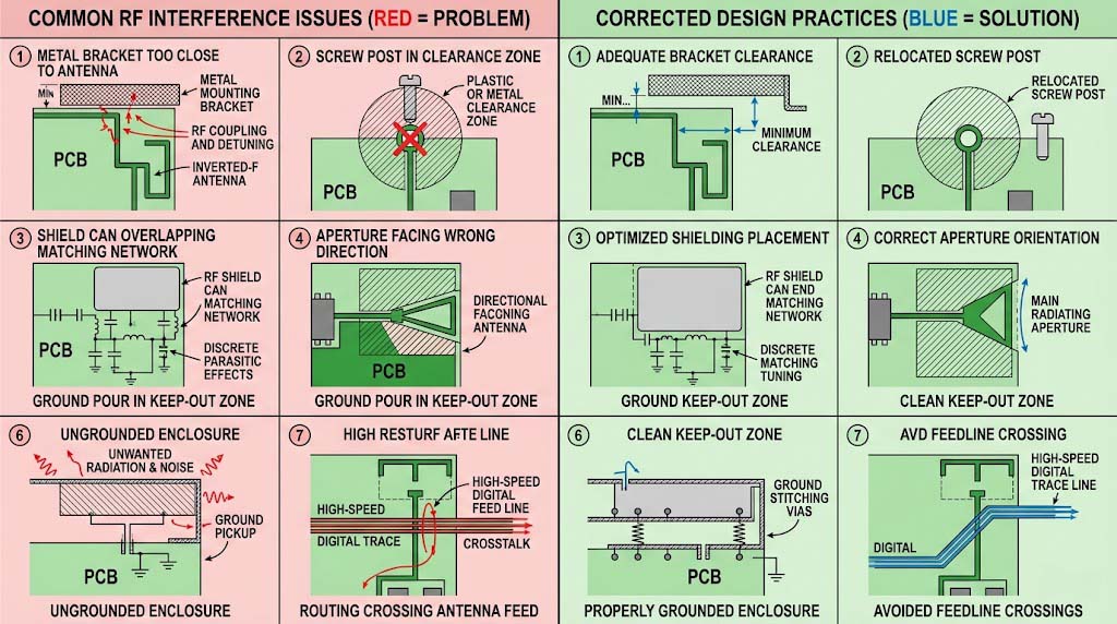
Internal Routing and Metal Structures
- Metal brackets and screw posts near antennas: These create parasitic impedance changes. A metal bracket within 3mm of a PCB antenna can detune it by 50-80MHz.
- Heat sinks near the RF section: Large finned heat sinks act as unintentional ground planes. Keep heat sinks at least 10mm from antennas and their feed networks.
- Cable routing across antenna keep-out zones: Coaxial cables and wiring harnesses running through antenna clearance areas couple RF energy and create unpredictable pattern changes.
Shielding Design
- Shield cans protect the RF front-end: A properly grounded shield can around the FEM, PA, and LNA reduces radiated susceptibility and prevents desense by 10-20dB.
- Over-shielding blocks the antenna: Extending a shield can too close to the antenna feed point adds shunt capacitance and detunes the match. Keep shield cans at least 3mm from RF traces and antenna feeds.
- Enclosure grounding affects common-mode noise: A floating metal enclosure can act as a resonant cavity and re-radiate noise. Ground the enclosure at multiple points with low-impedance connections (brass standoffs, conductive gaskets).
Co-Designing Structure and PCB Layout
Structural and PCB co-design follows a sequence of decisions that directly affect RF outcomes:
Co-Design vs Separate Design: Cost and Performance Comparison
| Design Phase | Co-Design Approach | Separate Design Approach | Cost Impact of Separate Design |
|---|---|---|---|
| Architecture | RF, ME, and ID teams define antenna location, enclosure material, and thermal path together | ME team designs enclosure independently based on ID concept | Late RF integration costs $5,000-20,000 in additional engineering |
| PCB Layout | Antenna keep-out zone and feed line reserved before component placement. ME provides bracket and screw locations | RF designer places antenna in last available space. ME constraints discovered after layout is frozen | PCB respin: $3,000-8,000 + 2-4 week schedule delay |
| Enclosure Design | Plastic window, antenna standoff, and aperture locations modeled in CAD alongside RF simulation | Enclosure designed for aesthetics and strength only. RF team asked to “make it work” after tooling | Mold modification: $8,000-20,000 + 3-6 week tooling delay |
| Prototyping | 3D-printed enclosure with antenna window used for OTA testing before steel mold commitment | First real RF measurement taken on production-intent units from the steel mold | Last-minute redesign: $20,000-50,000 + 8-12 week schedule impact |
| Certification | Pre-scan with prototype enclosure identifies and resolves issues before compliance testing | FCC/CE testing fails on first attempt. Root cause is enclosure-related | Second certification round: $15,000-40,000 additional test costs |
Practical Co-Design Workflow
- Phase 0 (Concept): Decide enclosure material (plastic vs metal) and antenna type (internal vs external) based on product tier and target cost.
- Phase 1 (Architecture): ME creates rough enclosure volume. RF identifies antenna position and keep-out zone. ID sketches around these constraints.
- Phase 2 (Detailed Design): RF simulates antenna with simplified enclosure model (metal boundaries, plastic windows). ME adds brackets, screw posts, and heat sinks at least 10mm from antenna zone.
- Phase 3 (Verification): Build 3D-printed prototype enclosure. Measure S-parameters, efficiency, and pattern. Adjust window size or antenna position if needed.
- Phase 4 (Tooling): Freeze enclosure design only after RF verification is complete. No last-minute ME changes without RF review.
Common Mechanical Interference Problems
Here are the most frequent mechanical-RF interference problems seen in wireless AP development, along with their typical symptoms:
- Metal enclosure too close to antenna: Signal strength drops 6-10dB. Range reduces by 40-60%. The antenna works on the bench but fails in the product. Fix: Add plastic window or increase clearance.
- Antenna keep-out zone invaded by copper pour or components: VSWR rises above 2.5:1. The antenna resonance shifts by 50-100MHz. Throughput drops at band edges. Fix: Enforce keep-out zone in PCB layout rules.
- Aperture position misaligned with intended coverage direction: The AP is ceiling-mounted but the signal radiates upward. Users below experience weak signal. Fix: Align apertures with target coverage zone during concept phase.
- Internal metal routing or brackets crossing the antenna feed: Intermittent performance, high retry rates, and unpredictable pattern changes. Fix: Route all metal structures at least 10mm from antenna and feed line.
- Shield can placed too close to antenna matching network: The pi-network values shift. The output power drops 2-4dB because the PA sees a mismatched load. Fix: Maintain 3-5mm clearance between shield can and RF components.
- Enclosure not grounded, creating a parasitic radiator: Spurious emissions appear on the radiated test. The product fails FCC/CE radiated emissions by 3-6dB. Fix: Ground the enclosure at 4+ points using conductive standoffs or fingerstock gaskets.
- Screw post or mounting boss within the antenna clearance zone: Localized impedance discontinuity. 1-3dB loss at specific frequencies. Fix: Relocate screw posts outside the clearance zone or use plastic hardware near antennas.
Balancing Industrial Design with RF Performance
Every wireless AP project faces tension between what looks good and what performs well. Here is how to make the trade-off systematically:
ID vs RF Priority by Product Type
| Product Type | ID Priority | RF Priority | Typical Enclosure | Key Balance Strategy |
|---|---|---|---|---|
| Consumer/SOHO AP | High (shelf appeal drives purchase) | Medium (must work, not necessarily best-in-class) | Plastic, custom shapes, multiple color options | Use internal PCB antennas with plastic enclosure. Optimize ID around antenna keep-out zone constraints |
| Enterprise Indoor AP | Medium (professional appearance, brand consistency) | High (reliability and coverage are the product) | Plastic or metal, ceiling-mount form factor | Metal enclosure with plastic antenna windows. Invest in antenna simulation and OTA testing |
| Outdoor/Industrial AP | Low (function dictates form) | Very high (environmental conditions already challenging) | Metal or high-grade plastic, IP67-rated | External antennas or slot antennas integrated into metal enclosure. Prioritize thermal management |
| Carrier/ISP AP | Low-Medium (must meet carrier branding guidelines) | Very high (carrier acceptance standards are strict) | Plastic, standardized form factor | Reference design-based. Co-design from Phase 0. Strict adherence to carrier performance benchmarks required |
Summary
Here are the core principles for maintaining RF performance in metal-enclosed wireless APs:
- Metal enclosure vs RF is a solvable problem: Metal reflects over 95% of incident RF energy, but plastic antenna windows, slot antennas, or external antennas provide reliable workarounds. The key is planning these features before tooling.
- Clearance is the single most important variable: Maintain at least 5-10mm between metal structures and antennas. Every millimeter of additional clearance below λ/4 improves efficiency by 1-3dB. For 2.4GHz, 10mm is the practical minimum. For 5GHz, 6mm.
- Aperture location determines coverage direction: Openings in the enclosure act as waveguide apertures. Place them on the surface that faces the intended coverage area. Ventilation grilles with holes smaller than λ/20 attenuate signals by 6-10dB.
- Internal metal structures create parasitic effects: Brackets, screw posts, and heat sinks within 5mm of antennas cause impedance shifts of 10-30Ω and frequency detuning of 40-80MHz. Keep all metal hardware at least 10mm from antenna zones.
- Co-design from Phase 0 eliminates costly fixes: Separate mechanical and RF design sequences result in mold modifications costing $8,000-20,000 and certification re-testing costing $15,000-40,000. Integrated co-design avoids these entirely.
- Plastic vs metal is a tier-dependent decision: Plastic enclosures support internal antennas and cost $3-8/unit. Metal enclosures offer superior shielding and thermal performance but cost $8-20/unit and require antenna window design.
This article is part of the comprehensive guide on how to balance RF performance and cost in wireless AP motherboard development. For related topics, explore our guides on wireless AP antenna design, PCB layout principles for RF, EMC certification, and OEM vs ODM selection for wireless AP motherboards.
Frequently Asked Questions
Q: Does a metal enclosure always degrade wireless AP RF performance?
Not always, but it always changes it. A metal enclosure reflects electromagnetic waves, which typically reduces omnidirectional coverage by 40-60% if no antenna window is provided. However, with proper design — plastic antenna windows (minimum 15x15mm for 2.4GHz), slot antennas, or external antenna connectors — the performance impact can be reduced to 1-3dB loss compared to a plastic enclosure. Some enterprise APs intentionally use metal enclosures with slot antennas to achieve a directional radiation pattern that improves coverage in one direction. The key is to design for the metal enclosure rather than treating it as an afterthought.
Q: What is the minimum distance I should keep between a metal enclosure wall and a 2.4GHz PCB antenna?
For 2.4GHz PCB antennas, maintain a minimum of 10mm clearance between the antenna and any metal enclosure surface. The ideal distance is λ/4 (approximately 31mm at 2.4GHz), which allows the antenna to radiate with minimal impedance shift. If clearance is limited to less than 10mm, expect efficiency loss of 3-6dB and a resonant frequency downshift of 40-80MHz. For 5GHz antennas, the minimum clearance is 6mm, with λ/4 (approximately 15mm) being ideal. These distances apply to all metal structures inside the enclosure, including brackets, screw posts, heat sinks, and shield cans. When clearance is constrained, use a plastic antenna window (replace the metal section above the antenna with a plastic insert) to recover 3-5dB of lost performance.
Q: Can I use a metal enclosure for a wireless AP and still get good WiFi coverage?
Yes, you can achieve good WiFi coverage with a metal enclosure, but you cannot simply place a standard PCB antenna inside a sealed metal box and expect it to work. Effective approaches include: (1) Plastic antenna windows — cut openings in the metal enclosure above the antenna and fill them with plastic inserts. A 20x30mm window for 2.4GHz adds only 1-2dB loss. (2) External antennas — use RP-SMA or N-type connectors to mount antennas outside the enclosure. This is the most common approach for outdoor and industrial APs. (3) Slot antennas — cut a precisely sized slot directly into the metal enclosure and use it as the radiating element. This approach requires antenna simulation expertise but produces a clean industrial design. Most enterprise APs use approach 1 or 3 and achieve coverage comparable to plastic-enclosed products.
Q: Does the thickness of a plastic enclosure wall affect antenna performance?
Yes, plastic enclosure wall thickness affects antenna performance through dielectric loading and insertion loss. A 1mm ABS wall (dielectric constant ≈2.8) introduces approximately 0.3-0.5dB of insertion loss at 2.4GHz and 0.5-0.8dB at 5GHz. Increasing the wall thickness to 2mm doubles the loss to 0.6-1.0dB at 2.4GHz and 1.0-1.6dB at 5GHz. The plastic also shifts the antenna resonant frequency downward by 10-30MHz depending on thickness and material grade. For best performance: keep wall thickness below 2mm in the antenna region, use low-loss materials (PC-ABS or polycarbonate with dielectric constant below 3.0), and tune the antenna matching network with the enclosure present during simulation, not in free space.
Q: How do ventilation holes in a metal enclosure affect RF signals?
Ventilation holes in metal enclosures can significantly degrade RF signals if not designed carefully. Holes smaller than λ/20 (approximately 6mm at 2.4GHz, 3mm at 5GHz) act as a reflective surface and can attenuate signals by 6-10dB. This effect is cumulative — the more holes, the higher the attenuation. For RF-transparent ventilation: (1) Use large single openings (at least λ/4 in the longest dimension) covered with a mesh that has holes smaller than λ/20 but keep the open area ratio above 70%. (2) Position ventilation holes on the side surfaces rather than on the surface facing the coverage zone. (3) If holes must be on the antenna-facing surface, leave a solid area at least 30x30mm directly above the antenna. The best practice is to keep the enclosure surface above the antenna completely solid and place all ventilation on other surfaces.
Q: What is the best way to ground a metal enclosure for optimal RF performance?
The best grounding strategy for a metal enclosure uses multiple low-impedance connections distributed around the PCB perimeter. Use at least 4 grounding points — one at each corner or along each edge — with brass standoffs or conductive gaskets providing a DC path from the PCB ground plane to the enclosure. The impedance of each ground connection should be below 10mΩ at DC and below 1Ω at RF frequencies. Avoid single-point grounding, which creates a resonant cavity effect and can re-radiate common-mode noise. Distributed grounding reduces enclosure resonance, lowers the noise floor by 3-6dB, and improves EMC performance by 10-20dB in radiated emissions tests. For outdoor enclosures, also ensure that the grounding system is corrosion-resistant — use stainless steel hardware with conductive gaskets rather than bare copper contacts.


